

Gemu SideStep Profibus DP, ACTRONIC Profibus DP, SideStep Industrial Operating Instructions Manual
Page 1
ACTRONIC
®
Profibus DP Operating instructions
SideStep® Industrial OPEN/CLOSE
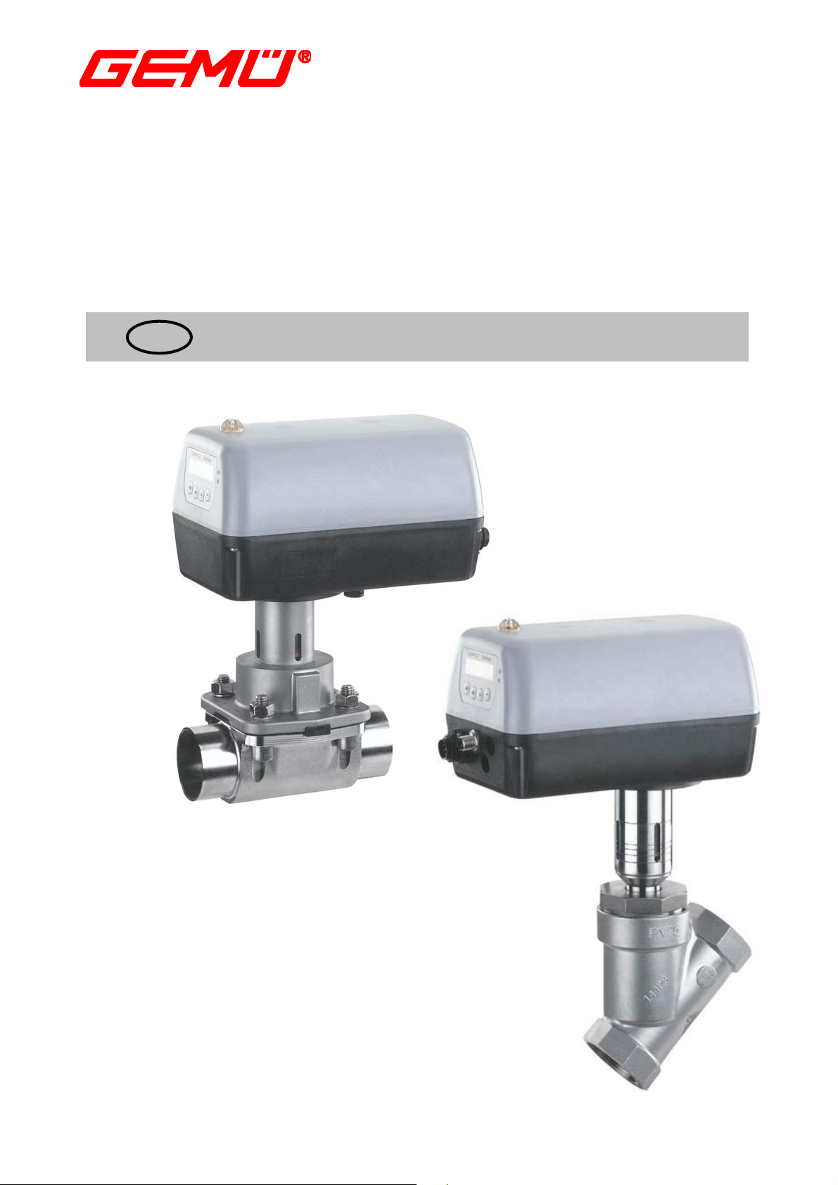
GEMÜ SideStep
®
Motorized Actuator
Industrial OPEN/CLOSE Profibus DP
GB OPERATING INSTRUCTIONS
Status 06.04.09
from version 1.0.6.0
1/42
Page 2

ACTRONIC
®
Profibus DP Operating instructions
SideStep® Industrial OPEN/CLOSE
CONTENTS
1. TECHNICAL DATA - GEMÜ SIDESTEP PROFIBUS DP 3
2. ELECTRICAL CONNECTIONS 3
2.1. GEMÜ SideStep industrial OPEN/CLOSE Profibus DP 3
2.2. RS-485 4
2.3. Profibus DP status LED 4
2.4. Supply voltage 4
2.4.1. 24V DC supply voltage 4
2.4.2. 120V 50/60Hz or 230V 50/60Hz supply voltage 4
3. WIRING IN THE PROFIBUS SYSTEM 5
4. SERIAL WIRING IN THE BUS SYSTEM 5
5. BUS WIRING VIA STUB 6
6. DIFFERENT CONFIGURATION MENU 6
7. CYCLIC PROFIBUS DATA 7
7.1. Set value and digital input 7
7.2. Valve position 7
7.3. Digital output 7
7.4. Parameter data: Parameters / Actions / Errors 8
7.4.1. No action 8
7.4.2. Change parameters 8
7.4.3. Request parameters 9
7.4.4. Read error list 10
7.4.5. Amount of active errors and readout of the active error 11
7.4.6. Amount of active warnings and readout of the actice warnings 12
7.4.7. Trigger action in the SideStep 12
7.4.8. Quit TravelTimeError 13
7.4.9. Quit Field bus Event 13
7.4.10. NoInit 14
7.4.11. Clear Error List 15
7.4.12 Set Default 15
7.4.13. Init valve 16
7.4.14. GoClose 16
7.4.15. GoOpen 17
8. EXTERNAL DIAGNOSTIC ERRORS 18
9. PARAMETER NUMBERS 19
10. CONFIGURATION EXAMPLE USING SIEMENS S7 23
2/42
Page 3
ACTRONIC
®
Profibus DP Operating instructions
SideStep® Industrial OPEN/CLOSE
1. Technical Data - GEMÜ SideStep Profibus-DP
Protocol flow
GSD data file G9ASSind.GSD
PNO-ID 0x2079
Baud rate 9.6 baud
19.2 baud
93.75 baud
187.5 baud
500 baud
1.5 Mbaud
3 Mbaud
6 Mbaud
12 Mbaud
Profibus address 26
(Default setting)
2. Electrical connections
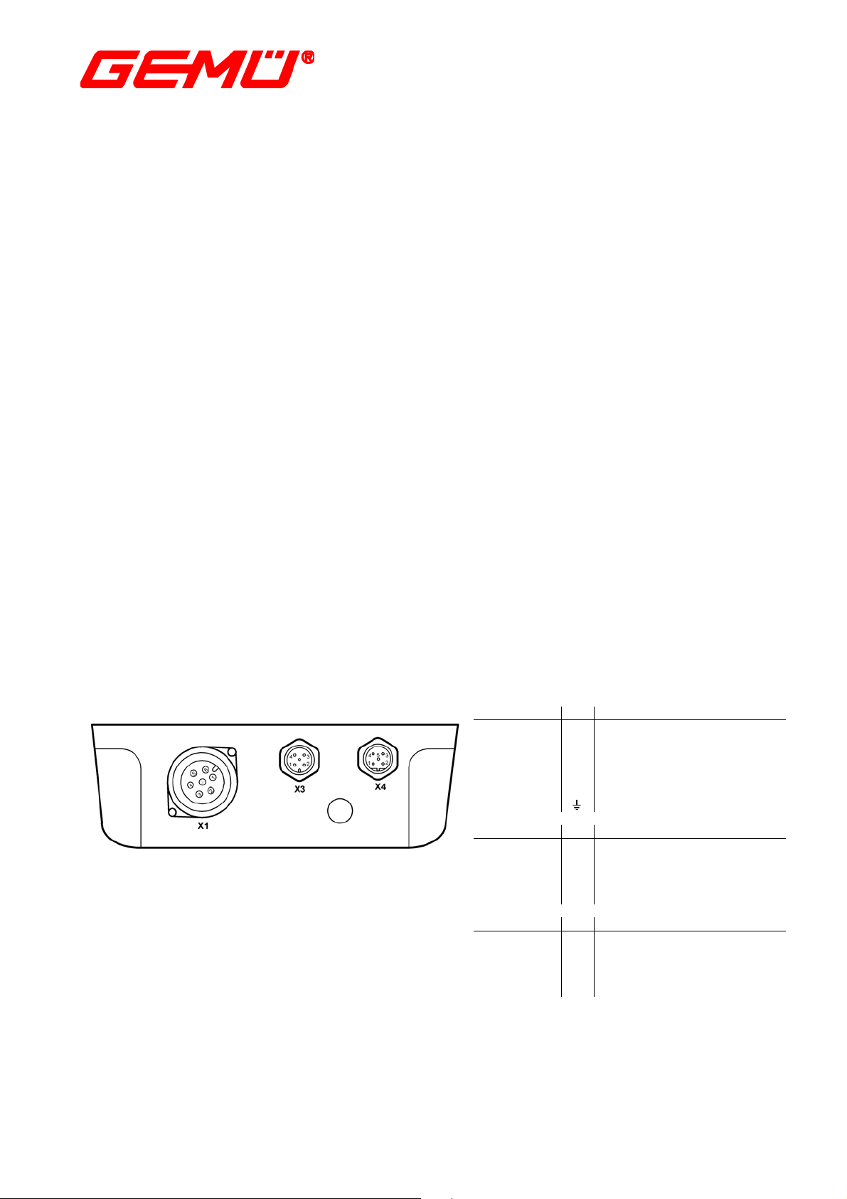
2.1. GEMÜ SideStep industrial OPEN/CLOSE Profibus DP
Connection Pin Signal name
X1 1 Uv, L1 / L+ supply voltage
Connector plug 2 Uv, N / L- supply voltage
3 n.c.
4 n.c.
5 n.c.
6 n.c.
PE conductor
Connection Pin Signal name
X3 1 n.c.
M12 plug 2 RxD/TxD-N
B coding 3 n.c.
PB in 4 RxD/TxD-P
5 Shield
Connection Pin Signal name
X4 1 BUS-VDC, +5V DC
M12 socket 2 RxD/TxD-N
B coding 3 DGNG
PB out 4 RxD/TxD-P
5 Shield
3/42
Page 4
ACTRONIC
®
Profibus DP Operating instructions
SideStep® Industrial OPEN/CLOSE
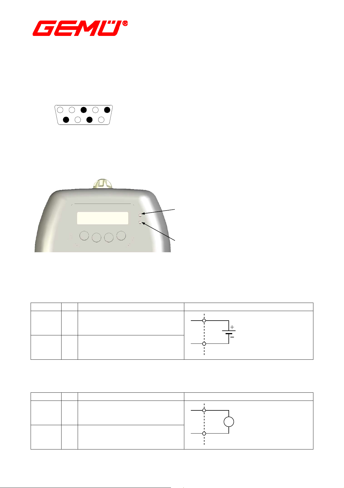
2.2. RS-485
1234
RxD/TxD-P
6789
VP +5
RxD/TxD-N
2.3. Profibus DP status LED
Red light – no bus connection
No light – bus connection ok
No function at Profibus DP design
DGND
5
Profibus DP status LED
2.4. Supply voltage
2.4.1. 24V DC supply voltage
Plug Pin Signal name Wiring
internal external
X1 1 Uv, L+ supply voltage 24V DC power
supply
X1 2 Uv, L- supply voltage
2.4.2. 120V 50/60Hz or 230V 50/60Hz supply voltage
Plug Pin Signal name Wiring
internal external
X1 1 Uv, L1 supply voltage AC power
supply
~
X1 2 Uv, N supply voltage
4/42
Page 5
ACTRONIC
r
SideStep® Industrial OPEN/CLOSE
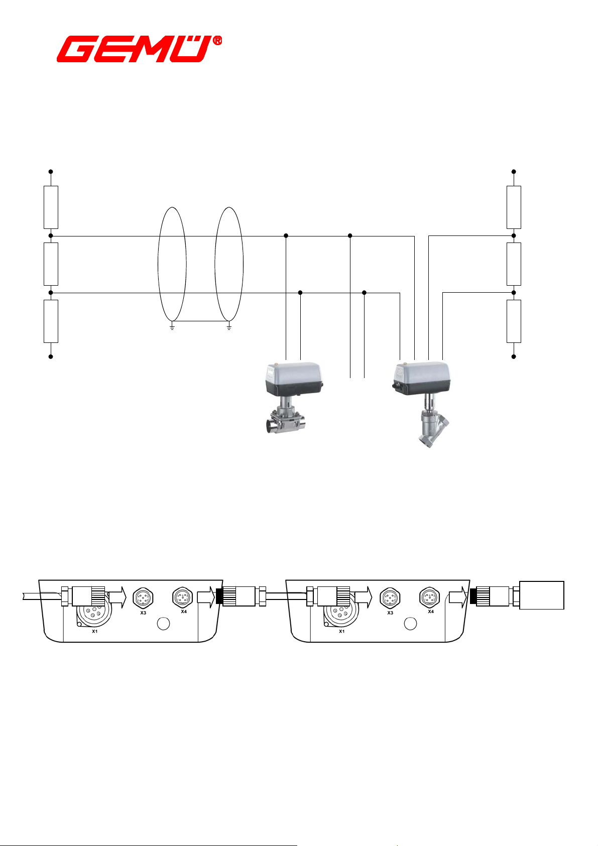
3. Wiring in the Profibus system
VP +5
390
Ω
220
Ω
390
DGND
Ω
Protection
With transmission rates
≥ 1.5 Mbaud no wiring with
drop cables
ground
Shield
Protection
ground
®
Profibus DP Operating instructions
Slave
VP +5
390
Ω
220
Ω
390
Ω
DGND
4. Serial wiring in the bus system
With a transmission rate ≥ 1.5 Mbaud.
Profibus
terminating
resisto
5/42
Page 6
ACTRONIC
r
SideStep® Industrial OPEN/CLOSE
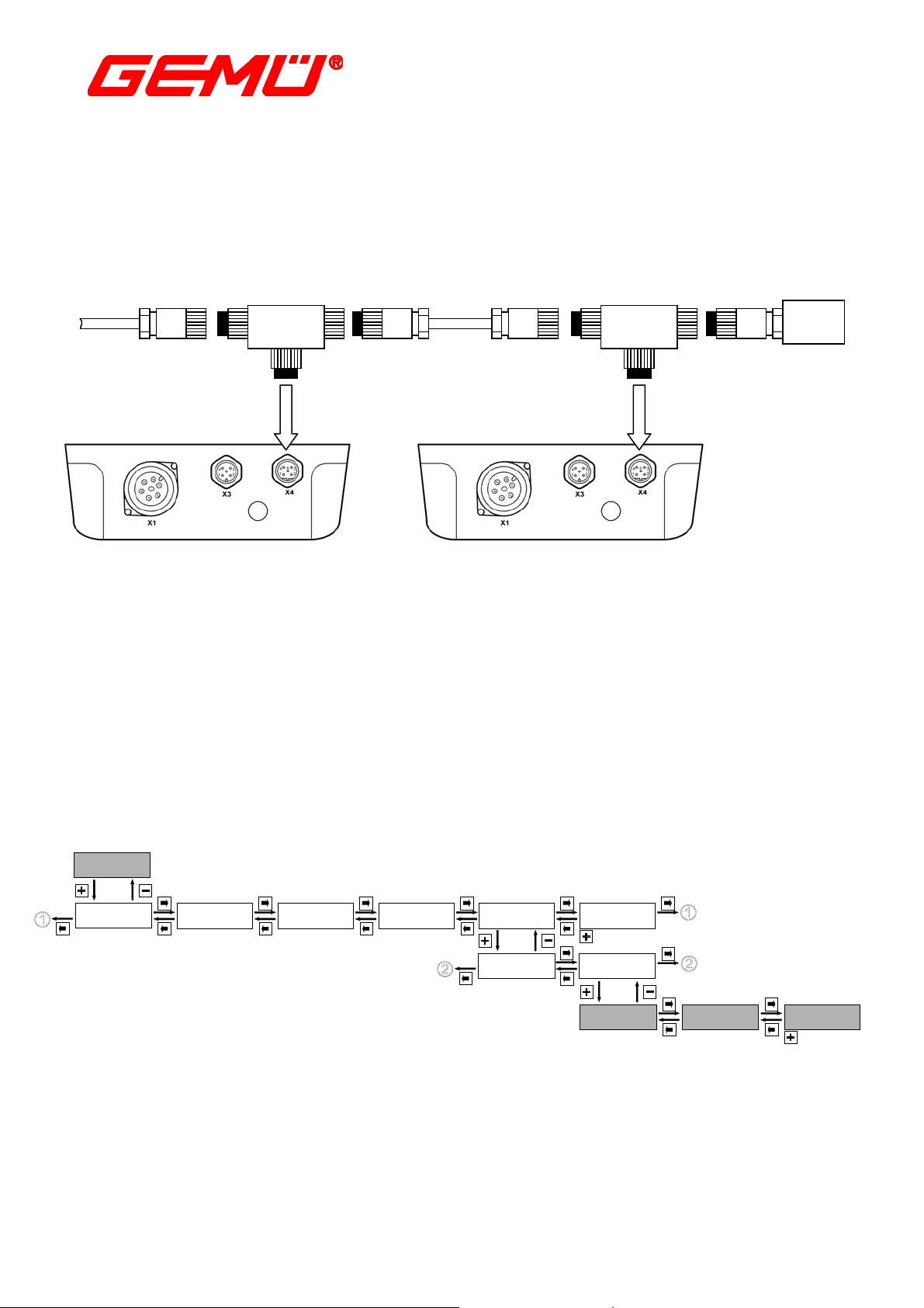
5. Bus wiring via drop cable
With a transmission rate ≤ 1.5Mbaud.
®
Profibus DP Operating instructions
Profibus
terminating
resisto
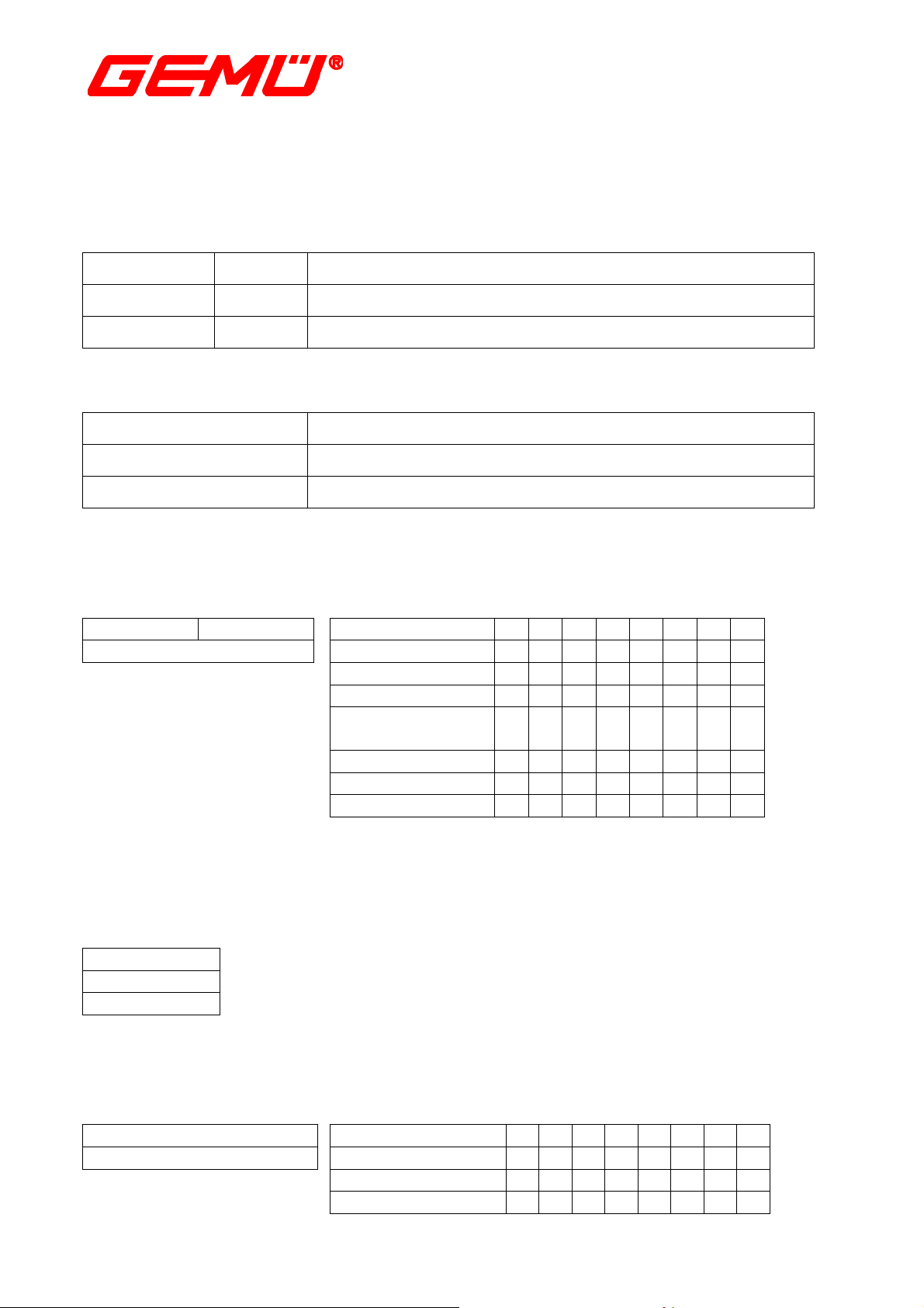
6. Different configuration menu
The GEMÜ SideStep with Profibus DP has the following expanded configuration menu
compared to the standard SideStep:
SETUP
Service
1
DP Adr
Determines the Profibus address of the actuator.
PwrOnT.Out
Defines the time between error recognition and message when the actuator is switched
on.
SetBasics
2
SetFunction
3
SetCalibration
4
Communication
5
IR-Port
5.1
Return
6
Fieldbus
5.2
DP adrr 26
PwrOnT.Out
Return
6/42
Page 7
ACTRONIC
®
Profibus DP Operating instructions
SideStep® Industrial OPEN/CLOSE
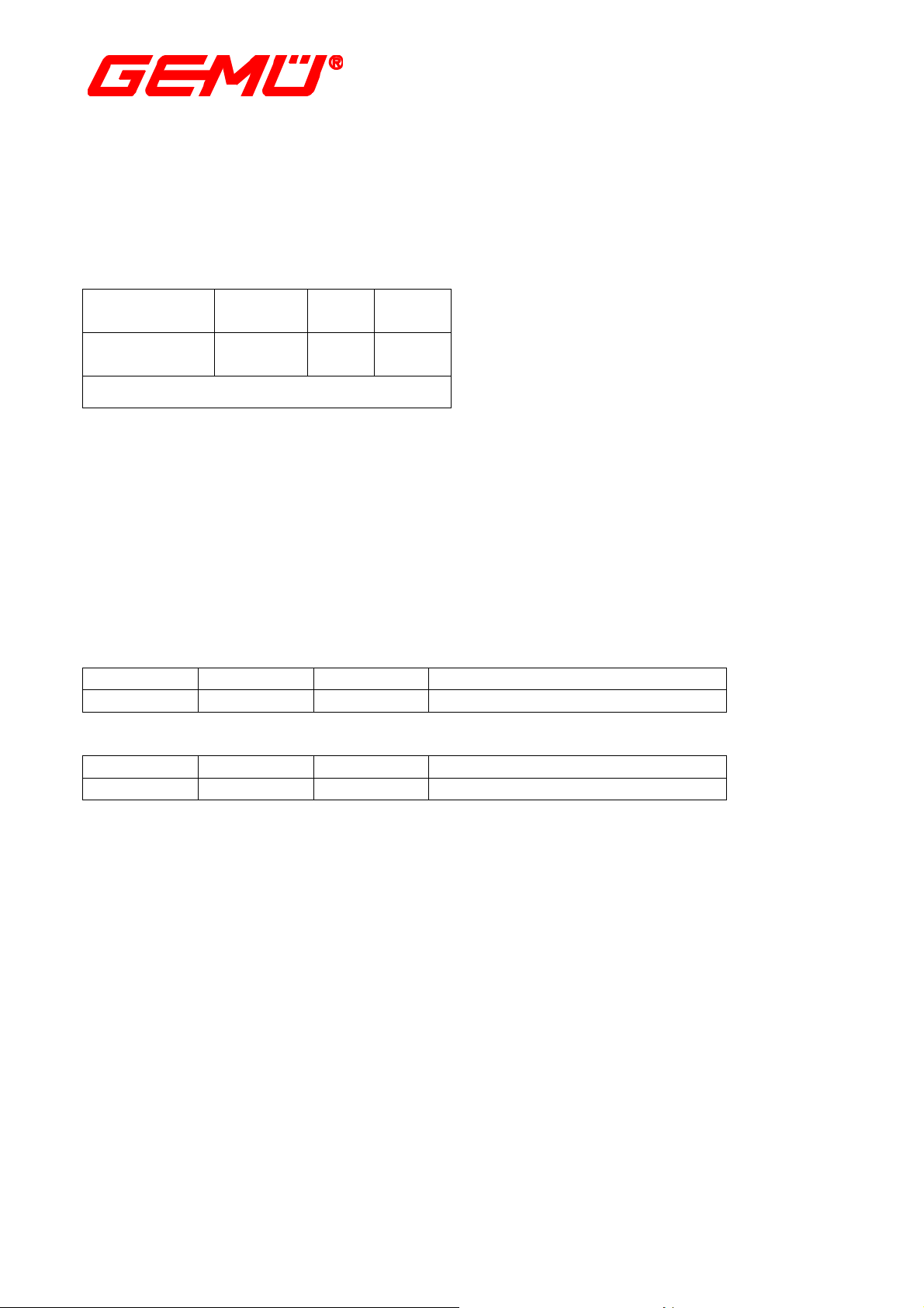
7. Cyclic Profibus data
Input data: (Profibus Å SideStep)
Addr. 0 Addr. 2 Addr. 3
2 bytes 1 byte 8 bytes
Valve position Dig. Out Parameters / Actions / Errors (see page 9)
Output data: (Profibus Æ SideStep)
Addr. 0 Addr. 1
1 byte 8 bytes
Set value and digital input Parameters / Actions / Errors (see page 9)
7.1. Set value and digital input
Profibus Æ SideStep
Set value Digital Input
1 byte Stop valve X X 0 0
Open valve X X 0 1
Close valve X X 1 0
Valve moves to X X 1 1
position Pref Dir
Digital input 1 0 1 X X
Digital input 2 1 0 X X
Digital input 1 + 2 1 1 X X
7.2. Valve position
Profibus Å SideStep
0..1000
Valve position
2 bytes
bit 7 6 5 4 3 2 1 0
7.3. Digital Output
Profibus Å SideStep
Digital Output
1 byte Digital output 1 0 1
Digital output 2 1 0
Digital output 1 + 2 1 1
7/42
bit 7 6 5 4 3 2 1 0
Page 8
ACTRONIC
®
Profibus DP Operating instructions
SideStep® Industrial OPEN/CLOSE
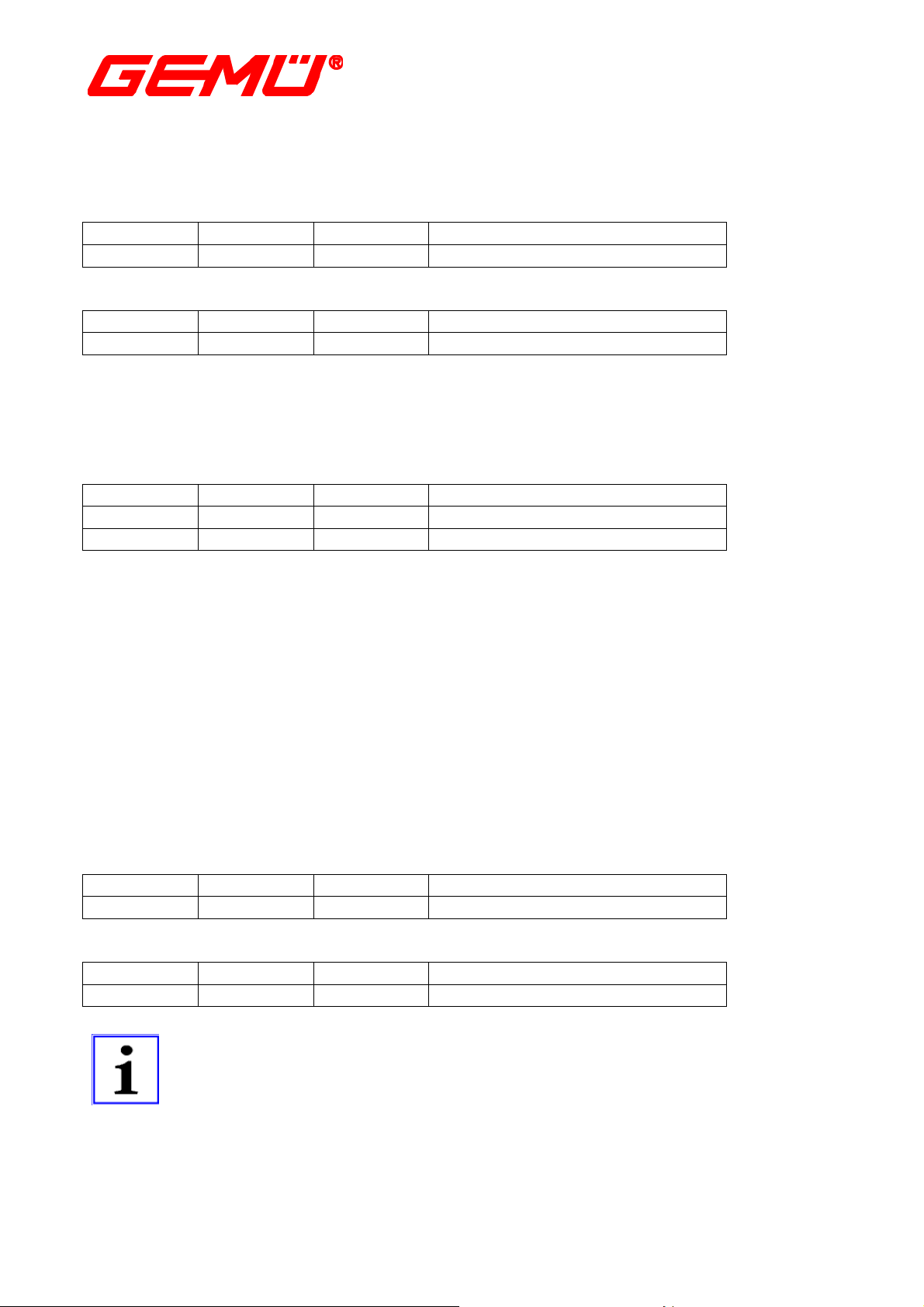
7.4. Parameter data: Parameters / Actions / Errors
SideStep ÅÆProfibus
Parameters / Actions / Errors:
Toggle
1
byte
If the same information is sent more than once, the data record needs to be changed via
the toggle byte.
Para
code
1
byte
8 bytes
Para
ID
2
bytes 4 bytes
Para
value
7.4.1. No action
When using the “N” (NOP) instruction, no action is carried out. The response is another
NOP instruction.
Inquiry from the master:
0xYY 0x4E (“N“) 0x00, 0x00 0x00, 0x00, 0x00, 0x00
1 byte 1 byte 2 bytes 4 bytes
Response of the SideStep:
0xYY 0x4E (“N“) 0x00, 0x00 0x00, 0x00, 0x00, 0x00
1 byte 1 byte 2 bytes 4 bytes
7.4.2. Change parameters
The “S“ (SET) instruction enables the change of a parameter in the SideStep via the
Profibus. As a response, the SideStep returns the SET instruction with the changed
parameter value. If the value is higher than the valid range, an external diagnostic error
with code 0x21 is generated; if below, the error generated has code 0x20.
Where the parameter does not exist, the diagnostic error triggered has code 0x22, and the
value returned is 0.
In case of a parameter change, the new value of the parameter is returned to the master
together with a SET instruction.
Where the parameter does not exist, the value returned is 0.
8/42
Page 9
ACTRONIC
®
Profibus DP Operating instructions
SideStep® Industrial OPEN/CLOSE
Inquiry from the master:
0xYY 0x53 (“S“) ID Value of the parameter
1 byte 1 byte 2 bytes 4 bytes
Response of the SideStep:
0xYY 0x53 (“S“) ID Value of the parameter
1 byte 1 byte 2 bytes 4 bytes
The individual parameters of the GEMÜ SideStep are on page 19.
Ex: The Mode parameter needs to be changed to Manual.
0xYY 0x53 (“S“) ID Value of the parameter
Mode Manual
0xYY 0x53 0x64 0x00, 0x00, 0x00, 0x02
7.4.3. Request parameters
The “G“ (GET) instruction is used to request from the SideStep the value of a parameter
via the Profibus. The SideStep responds with a GET instruction containing the parameter
value.
Where the parameter does not exist, an external diagnostic error with code 0x22 is
triggered.
Inquiry from the master:
0xYY 0x47 (“G“) ID2 0x00 0x00 0x00 0x00
1 byte 1 byte 2 bytes 4 bytes
Response of the SideStep:
0xYY 0x47 (“G“) ID Value of the parameter
1 byte 1 byte 2 bytes 4 bytes
When the parameter value in the GEMÜ SideStep changes, it is
immediately sent to the Profibus master. There is no need to
continuously request the parameter.
9/42
Page 10
ACTRONIC
®
Profibus DP Operating instructions
SideStep® Industrial OPEN/CLOSE
7.4.4. Read error list
The error list is requested using the “E“ (Error List) instruction.
Inquiry from the master:
0xYY 0x45 (“E“) Serial num-
ber of error
in the list
1 byte 1 byte 2 bytes 4 bytes
The first error is requested with 0x00 0x00
Response of the SideStep:
0xYY 0x45 (“E“) Serial num-
ber of error
in the list
1 byte 1 byte 2 bytes 4 bytes
Attention:
• When a new error occurs, the serial numbering of the listed errors changes.
Error 0 then becomes Error 1, Error 1 becomes Error 2, etc.
• Once the error list is full, the oldest error in the list is deleted.
• If no entry on the required number is found in the error list, an external
diagnostic error with code 0x34 is triggered. In this case the response value
is 0xFF 0xFF 0xFF 0xFF
• With number 0 the current error can be monitored
• If there is no error in the error list, error 0x00 0x00 0x00 0x00 is displayed
0x00, 0x00, 0x00, 0x00
Error information
10/42
Page 11
ACTRONIC
®
Profibus DP Operating instructions
SideStep® Industrial OPEN/CLOSE
7.4.5. Amount of active errors and readout of the active error
The “D“ instruction is used to request the amount of active errors and the active error
selected using the ID.
Inquiry from the master:
0xYY 0x44 (“D“) Number of
active error
1 byte 1 byte 2 bytes 4 bytes
The first error is requested with 0x00 0x01.
Response of the SideStep:
0xYY 0x44 (“D“) Number of
active error
1 byte 1 byte 2 bytes 4 bytes
Example:
The SideStep motor does not move during the time shown in the "TravelTime" parameter.
Error "022: TRAVEL T ERR" is triggered, the error is active.
Inquiry from the master:
0x00 0x44 0x00, 0x00 0x00, 0x00, 0x00, 0x00
Response of the SideStep:
0x00 0x44 0x00, 0x00
Example:
An error with error number (ID) 0x15 or 21
Error list
Error name Parameter
ID
Hex
NO ERROR 0x00 0x00 0 There are no errors
POWER FAIL 0x00 0x14 20 Power supply failure (only with optional emergency power
TRAVEL T ERR 0x00 0x15 21 Potentiometer error during normal operation
Bus Fault 0x00 0x28 40 Bus fault was recognized
Parameter
ID
Dec
0x00, 0x00, 0x00, 0x00
Amount of
active errors
0x00, 0x01, 0x00, 0x15
is active.
dec
supply module)
Value of active
error (selected
via ID)
Description
11/42
Page 12
ACTRONIC
®
Profibus DP Operating instructions
SideStep® Industrial OPEN/CLOSE
7.4.6. Amount of active warnings and readout of the active warning
The "W" instruction advises the Profibus of the amount of active warnings. It functions
analogous to the "D" instruction (readout active error messages) but refers to warnings
rather than error messages.
Inquiry from the master:
0xYY 0x57 („W“) Number of
active
warning
1 byte 1 byte 2 bytes 4 bytes
0x00, 0x00, 0x00, 0x00
7.4.7. Trigger action in the SideStep
The ”A“ (Action) instruction is used to trigger an action in the SideStep. Depending on the
action to be triggered, additional parameters may be required.
As long as an action is active, no other action may be triggered. Where this is attempted,
the SideStep will ignore the new action and generate an external diagnostic error with
code 0x40.
Inquiry from the master:
0xYY 0x41 (“A“) ID Parameter
1 byte 1 byte 2 bytes 4 bytes
Only one action may be active at a time. If no action is active, the SideStep responds as described in the individual actions.
If an action is active, the field bus will create the following response:
Response of the SideStep:
0xYY 0x41 (“A“) ID 0xFF Source Number
1 byte 1 byte 2 bytes 1 byte 1 byte 2 bytes
Source:
Active action was started via the GEMÜ SideStep keypad.
Î Acknowledge (quit) at the GEMÜ SideStep
Active action was started via the e.sy-com interface of the GEMÜ
SideStep.
Î Close active browser window
Active action was started via the field bus.
Î Quit with instruction "Q" or
Î Select action again and quit
0x01
0x02
0x03
12/42
Page 13
ACTRONIC
®
Profibus DP Operating instructions
SideStep® Industrial OPEN/CLOSE
7.4.8. Quit TravelTimeError
Quit TravelTimeError is used to acknowledge a "TravelTimeError" that has occurred.
Instruction from the master
0xYY 0x41 0x00, 0x07 Function
1 byte 1 byte 2 bytes 4 bytes
Function:
Acknowledge TravelTimeError 0x00,0x00,0x00,0x01
Response of the SideStep:
0xYY 0x41 0x00, 0x07 Status
1 byte 1 byte 2 bytes 4 bytes
Status:
TravelTimeError acknowledged 0x00,0x00,0x00,0x01
TravelTimeError not acknowledged 0x00, 0x00, 0x00, 0x02
7.4.9. Quit field bus event
The instruction "Q" (Quit) is used to stop an active event.
This event acknowledges all active events activated via the field bus.
Instruction from the master:
0xYY 0x51 („Q“) 0x00 0x00 0x00 0x00 0x00 0x00
1 byte 1 Byte 2 bytes 4 bytes
Response of the SideStep:
0xYY 0x51 („Q“) 0x00 0x00 0x00 0x00 0x00 0x00
1 byte 1 byte 2 byte 4 bytes
13/42
Page 14
ACTRONIC
®
Profibus DP Operating instructions
SideStep® Industrial OPEN/CLOSE
7.4.10. NoInit
With “NoInit“, the actuator can be opened and closed manually if not yet initialised.
Where this action is activated once the SideStep has been initialised, the SideStep will
generate an external diagnostic error with code 0x42.
Instruction from the master:
0xYY 0x41 (“A“) 0x00, 0x01 Function
1 byte 1 byte 2 bytes 4 bytes
Function:
Stop valve 0x00, 0x00, 0x00, 0x00
Open slowly 0x01, 0x00, 0x00, 0x00
Open quickly 0x02, 0x00, 0x00, 0x00
Close slowly 0x03, 0x00, 0x00, 0x00
Close quickly 0x04, 0x00, 0x00, 0x00
Open with PWM [0..1000] 0x05, 0x00, PWM High, PWM Low
Close with PWM [0..1000] 0x06, 0x00, PWM High, PWM Low
End event 0x07, 0x00, 0x00, 0x00
The status reported is the current valve function selected.
Response of the SideStep:
0xYY 0x41 (“A“) 0x00, 0x01 Status
1 byte 1 byte 2 bytes 4 bytes
Status:
Stop valve 0x00, 0x00, 0x00, 0x00
Open slowly 0x01, 0x00, 0x00, 0x00
Open quickly 0x02, 0x00, 0x00, 0x00
Close slowly 0x03, 0x00, 0x00, 0x00
Close quickly 0x04, 0x00, 0x00, 0x00
Open with PWM [0..1000] 0x05, 0x00, PWM High, PWM Low
Close with PWM [0..1000] 0x06, 0x00, PWM High, PWM Low
End event 0x07, 0x00, 0x00, 0x00
14/42
Page 15
ACTRONIC
®
Profibus DP Operating instructions
SideStep® Industrial OPEN/CLOSE
7.4.11. Clear Error List
This action clears the entries from the error list.
Instruction from the master:
0xYY 0x41 (“A“) 0x00, 0x02 0x00, 0x00, 0x00, 0x00
1 byte 1 byte 2 bytes 4 bytes
Response of the SideStep:
0xYY 0x41 (“A“) 0x00, 0x02 Status
1byte 1 byte 2 bytes 4 bytes
Status:
Error list cleared (action is ended) 0x00, 0x00, 0x00, 0x01
Error list not cleared (action remains active) 0x00, 0x00, 0x00, 0x02
7.4.12. Set Default
This action sets the SideStep to the default state.
Instruction from the master:
0xYY 0x41 (“A“) 0x00, 0x03 0x00, 0x00, 0x00, 0x00
1 byte 1 byte 2 bytes 4 bytes
Response of the SideStep:
0xYY 0x41 (“A“) 0x00, 0x03 Status
1 byte 1 byte 2 bytes 4 bytes
Status:
Default setting loaded (action is ended) 0x00, 0x00, 0x00, 0x01
Default setting not loaded (action remains active) 0x00, 0x00, 0x00, 0x02
15/42
Page 16
ACTRONIC
®
Profibus DP Operating instructions
SideStep® Industrial OPEN/CLOSE
7.4.13. Init valve
This action initialises the valve. The SideStep here determines the open and closed
position.
Instruction from the master:
0xYY 0x41 (“A“) 0x00, 0x04 Function
1 byte 1 byte 2 bytes 4 bytes
Function:
Start initialisation 0x00, 0x00, 0x00, 0x01
Cancel initialisation 0x00, 0x00, 0x00, 0x02
Response of the SideStep:
0xYY 0x41 (“A“) 0x00, 0x04 Status
1 byte 1 byte 2 bytes 4 bytes
In the status, the SideStep reports the action currently taken.
Status:
Initialisation inactive 0x00, 0x00, 0x00, 0x00
Closed position determined 0x00, 0x00, 0x00, 0x01
Open position determined 0x00, 0x00, 0x00, 0x02
7.4.14. GoClose
The motor moves the valve to the closed position. Once the valve is in the required
position, this needs to be communicated to the SideStep. This then takes the position as
"closed".
Instruction from the master:
0xYY 0x41 (“A“) 0x00, 0x05 Function
1 byte 1 byte 2 bytes 4 bytes
Function
Go to closed position 0x00,0x00,0x00,0x01
In closed position 0x00,0x00,0x00,0x02
Cancel Close function (ESC) 0x00,0x00,0x00,0x03
Response of the SideStep:
0xYY 0x41 (“A“) 0x00, 0x05 Status
1 byte 1 byte 2 bytes 4 bytes
Status:
Go to closed position 0x00,0x00,0x00,0x01
In closed position 0x00,0x00,0x00,0x02
Close function cancelled 0x00,0x00,0x00,0x03
16/42
Page 17
ACTRONIC
®
Profibus DP Operating instructions
SideStep® Industrial OPEN/CLOSE
7.4.15. GoOpen
The motor moves the valve to the open position. Once the valve is in the required
position, this needs to be communicated to the SideStep. This then takes the position as
"open".
.
Instruction from the master:
0xYY 0x41 (“A“) 0x00, 0x06 Function
1 byte 1 byte 2 bytes 4 bytes
Function:
Go to open position 0x00,0x00,0x00,0x01
In open position 0x00,0x00,0x00,0x02
Cancel Open function (ESC) 0x00,0x00,0x00,0x03
Response of the SideStep:
0xYY 0x41 (“A“) 0x00, 0x06 Status
1 byte 1 byte 2 bytes 4 bytes
Status:
Go to open position 0x00,0x00,0x00,0x01
In open position 0x00,0x00,0x00,0x02
Open function cancelled 0x00,0x00,0x00,0x03
17/42
Page 18

ACTRONIC
®
Profibus DP Operating instructions
SideStep® Industrial OPEN/CLOSE
8. External diagnostic errors
Defined error messages:
Error ID Error
0x01 Data length service data from master to slave incorrect
0x02 Data length service data from slave to master incorrect
0x20 Specified parameter value too low
0x21 Specified parameter value too high
0x22 Parameter does not exist
0x30 Error in SideStep
0x31 Error in SideStep acknowledged
0x32 Warning in SideStep
0x33 Warning in SideStep acknowledged
0x34 No error list entry on the requested number available
0x40 Event active in SideStep, therefore no new event possible.
0x41 Active action cannot be affected by Profibus
0x42 NoInit not available
0x43 Event doesn´t exist
18/42
Page 19
ACTRONIC
®
Profibus DP Operating instructions
SideStep® Industrial OPEN/CLOSE
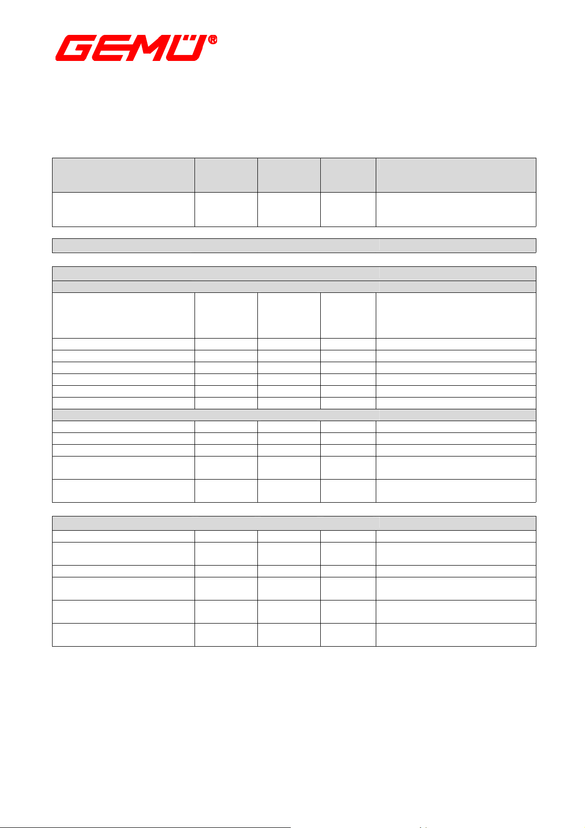
9. Parameter numbers
Parameter Parameter
ID
Hex
Mode 0x64 100 Write 0: OFF
SETUP
Service
I/O Status
ActiveParaSet 03E8 1000 Read 0: P1
Pot Min 03E9 1001 Read [0..1000] *0.1 %
Pot Max 03EA 1002 Read [0..1000] *0.1 %
Pos W 03ED 1005 Read [0..1000] *0.1 %
Pos X 03EE 1006 Read [0..1000] *0.1 %
Pot Abs 03EF 1007 Read [0..1000] *0.1 %
Pos Ctrl Out 03F0 1008 Read [-1000..1000] *0.1 %
Diagnosis
Operating hour 044C 1100 Read [0..99 999] h
Operating minute 044D 1101 Read [0..59] min
Operating second 044E 1102 Read [0..59] s
Warnings 044F 1103 Write 0: ON
Errors 0450 1104 Write 0: ON
SetBasics
D.Refresh 07D1 2001 Write [1..10] *0.1s
Dlight 07D2 2002 Write 0: ON
AutoReturn 07D3 2003 Write [1..60] min
HelpLanguage 07D4 2004 Write 0: D
Helptext 07D5 2005 Write 0: ON
PwrOnMode 07DF 2015 Write 0 : fast
Parameter
ID
Dec
Access Value range
1: Auto
2: Manual
1: P2
2: P3
3: P4
1: OFF
1: OFF
1: ON Key
1: GB
1: OFF
1 : safe
19/42
Page 20
ACTRONIC
®
Profibus DP Operating instructions
SideStep® Industrial OPEN/CLOSE
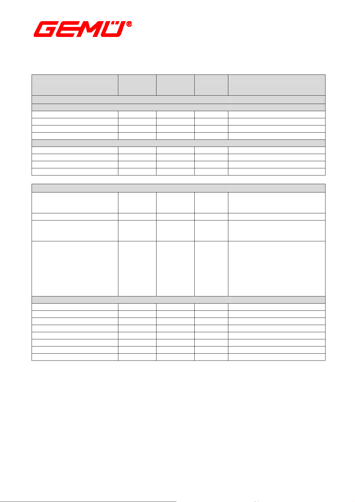
Parameter Parameter
ID
Hex
SetBasics
Speed Adj
StartSpOpen 07D7 2007 Write [0..1000] *0.1 %
StartSpClose 07D8 2008 Write [0..1000] *0.1 %
StopSpOpen 07D9 2009 Write [0..1000,-1] *0.1 %
StopSpClose 07DA 2010 Write [0..1000,-1] *0.1 %
Force ADj
InitFOpen 07DB 2011 Write [0..550] *0.1 %
InitFClose 07DC 2012 Write [0..550] *0.1 %
ForceOpen 07DD 2013 Write [0..550] *0.1 %
ForceClose 07DE 2014 Write [0..550] *0.1 %
SetFunction
PrefDir 0BB8 3000 Write 0: Close
DeadBand 0BB9 3001 Write [1..250] *0.1%
PwFailDir ** 0BBA 3002 Write 0: Close
CpyParaSet 0BBB 3003 Write 0: OFF
PosCtrl
Pos P 0C80 3200 Write [0..1000] *0.1
Pos D 0C81 3201 Write [0..1000] *0.1
Pos T 0C82 3202 Write [1..5000] ms
MinPos 0C83 3203 Write [0..1000] *0.1 %
MaxPos 0C84 3204 Write [0..1000] *0.1 %
closeTight 0C85 3205 Write [0..200] *0.1 %
openTight 0C86 3206 Write [800..1000] *0.1 %
TightTime 0C87 3207 Write [0..1200] *0.1 s
** only available with emergency power supply module version
Parameter
ID
Dec
Access Value range
1: Open
2: Hold
1: Open
2: Hold
1: P1<=W
2: P1=>P2
3: P1<=P2
4: P1=>P3
5: P1<=P3
6: P1=>P4
7: P1<=P4
20/42
Page 21
ACTRONIC
®
Profibus DP Operating instructions
SideStep® Industrial OPEN/CLOSE
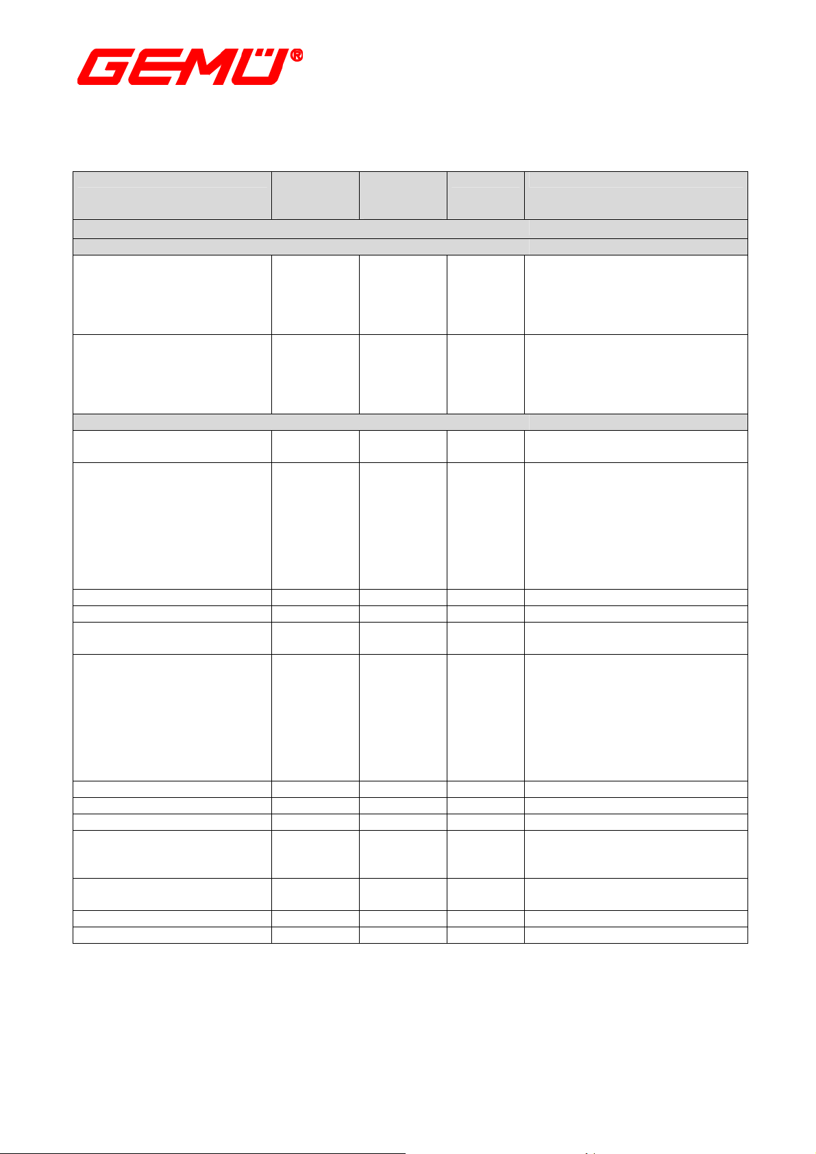
Parameter Parameter
ID
Hex
SetFunction
Digital Input
In 1 0CE4 3300 Write 0: OFF
In 2 0CE5 3301 Write 0: OFF
Digital Output
K1 Switch 0D48 3400 Write 0: NO
K1 Fn 0D49 3401 Write 0: No
AlarmMinK1 0D4A 3402 Write [2..998] *0.1%
AlarmMaxK1 0D4B 3403 Write [2..998] *0.1%
K2 Switch 0D4C 3404 Write 0: NO
K2 Fn 0D4D 3405 Write 0: No
AlarmMinK2 0D4E 3406 Write [2..998] *0.1%
AlarmMaxK2 0D4F 3407 Write [2..998] *0.1%
ErrorTime 0D50 3408 Write [2..1000] *0.1s
ErrorAction 0D51 3409 Write 0: Close
TravelTErrFn 0D52 3410 Write 0: OFF
TravelLevel 0D53 3411 Write [0..1000] *0.1 %
TravelTime 0D54 3412 Write [0..1200] *0.1 s
Parameter
ID
Dec
Access Value range
1: OFF/ON
2: Save/ON
3: ParamSetB0
4: ParamSetB1
1: OFF/ON
2: Save/ON
3: ParamSetB0
4: ParamSetB1
1: NC
1: P min
2: P max
3: P min/max
4: W min
5: Active
6: Error
7: Warning
1: NC
1: P min
2: P max
3: P min/max
4: W min
5: Active
6: Error
7: Warning
1: Open
2: Hold
1: ON
21/42
Page 22
ACTRONIC
®
Profibus DP Operating instructions
SideStep® Industrial OPEN/CLOSE
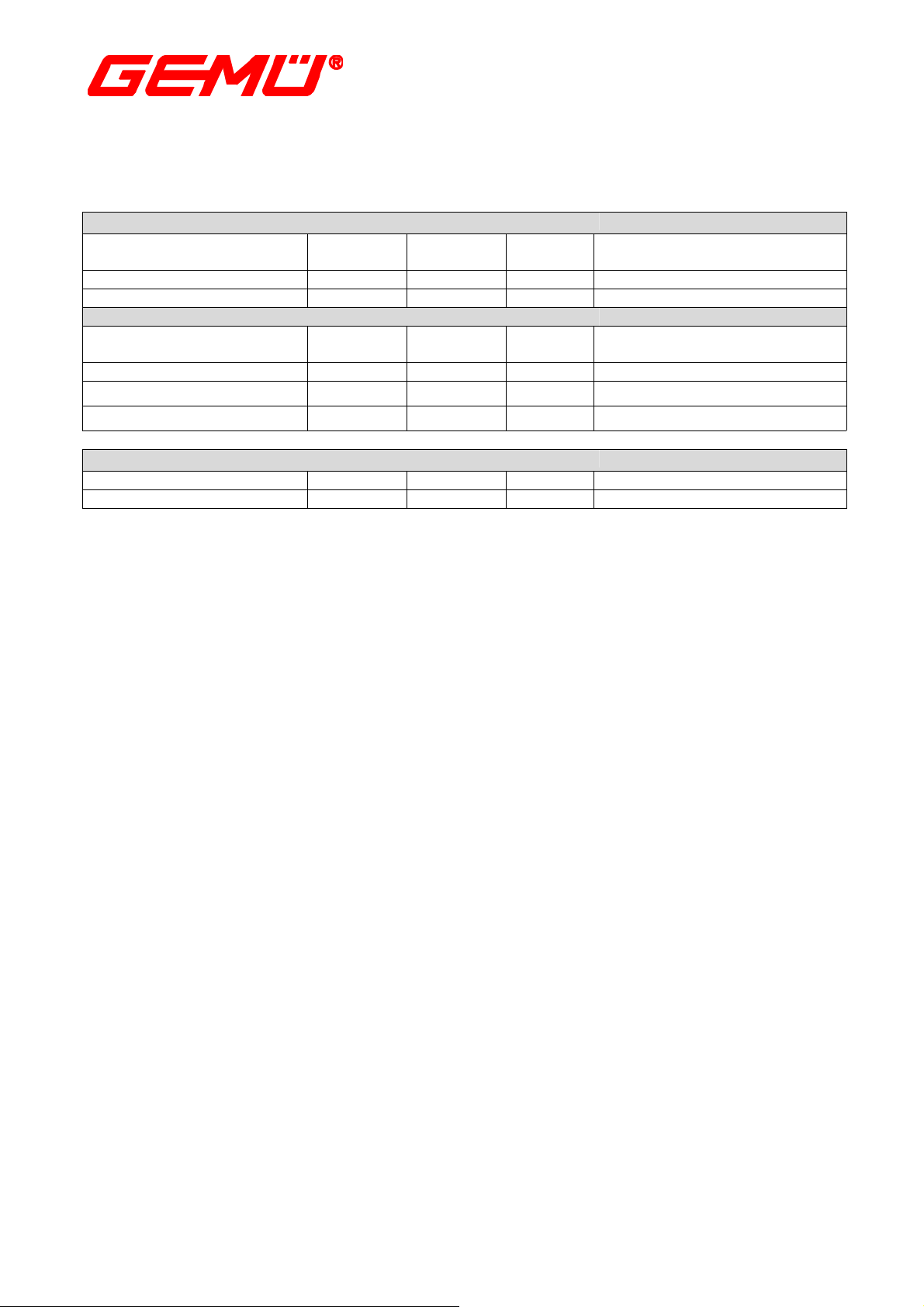
SetCalibration
Pot Dir 0FA0 4000 Write 0: rise
OutMinPos 0FA1 4001 Write [0..1000] *0,1 %
OutMaxPos 0FA2 4002 Write [0..1000] *0,1 %
Scaling
Scaling 1068 4200 Write 0: OFF
Decimalpoint 1069 4201 Write [0..2]
4mA≙
20mA≙
Communication
Profibus ID 13EC 5100 Write [1..126]
PwrOnT.Out 13ED 5101 Write 0…300 s
1: fall
1: ON
106A 4202 Write [-999..9999]
106B 4203 Write [-999..9999]
22/42
Page 23
ACTRONIC
®
Profibus DP Operating instructions
SideStep® Industrial OPEN/CLOSE
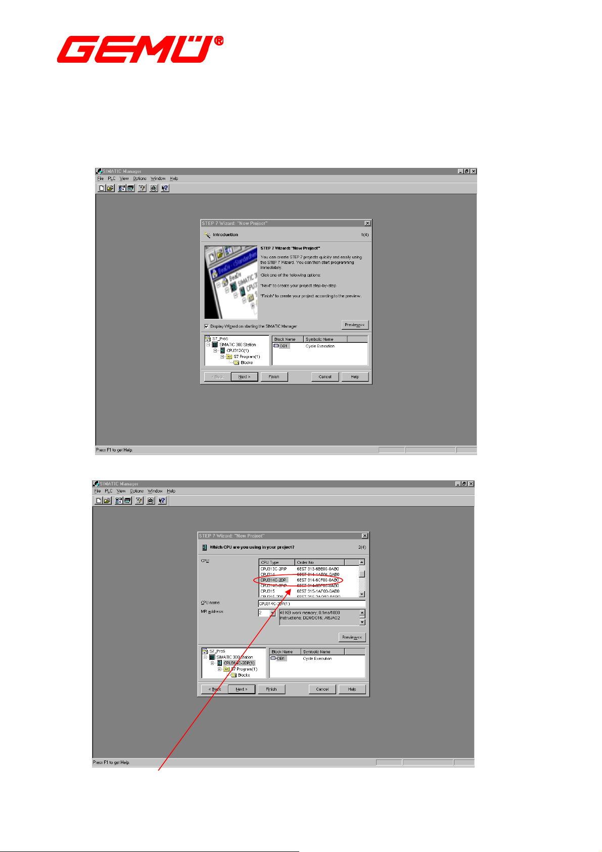
10. Configuration example using SIEMENS S7
(e.g. GEMÜ 1436)
Start SIMATIC Manager and click on “Next“ to continue
Select PLC type and click on “ Next“ to continue
23/42
Page 24
ACTRONIC
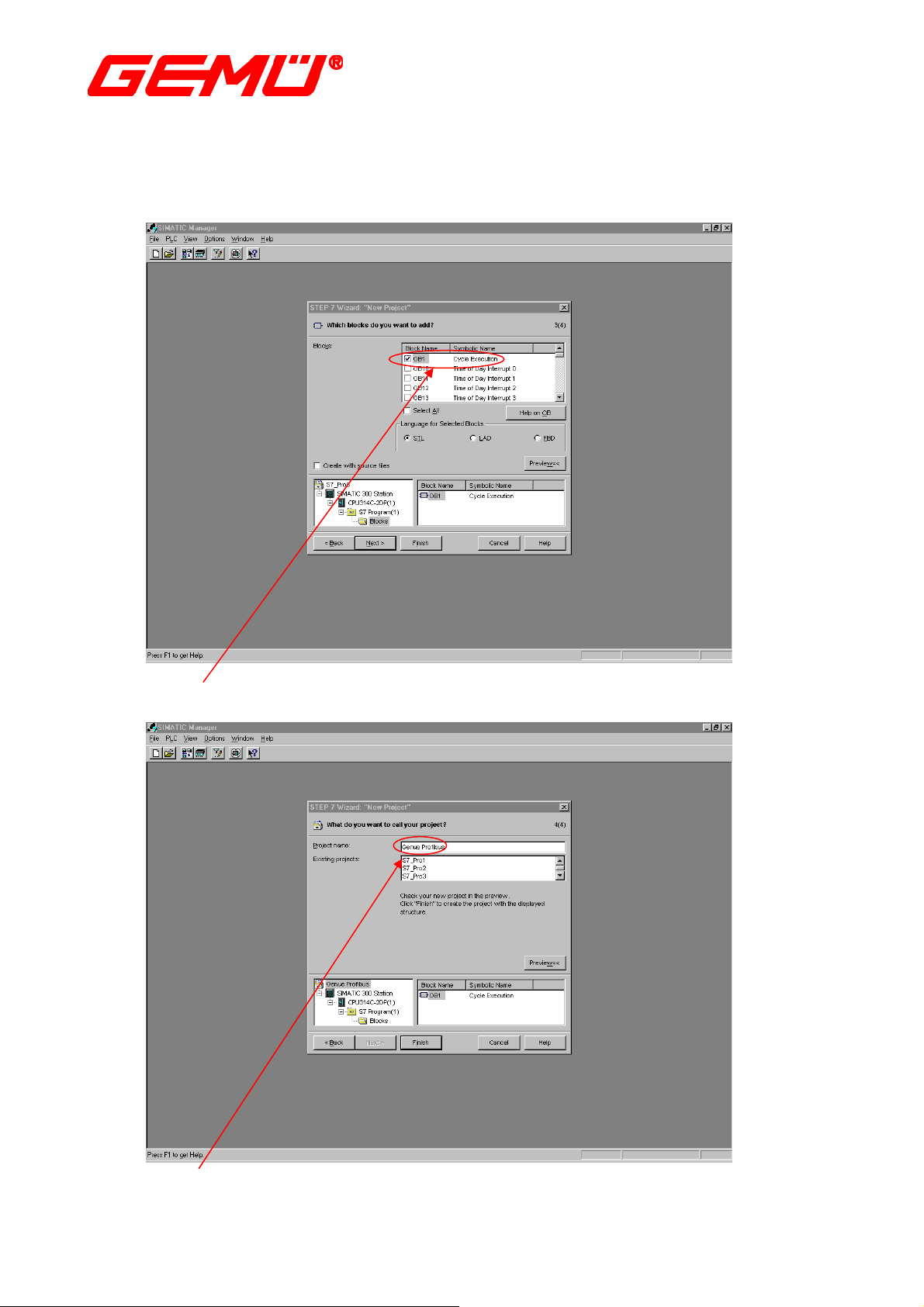
SideStep® Industrial OPEN/CLOSE
Insert new module and click on “ Next“ to continue
Enter project name and create project by clicking on “Finish“
®
Profibus DP Operating instructions
24/42
Page 25
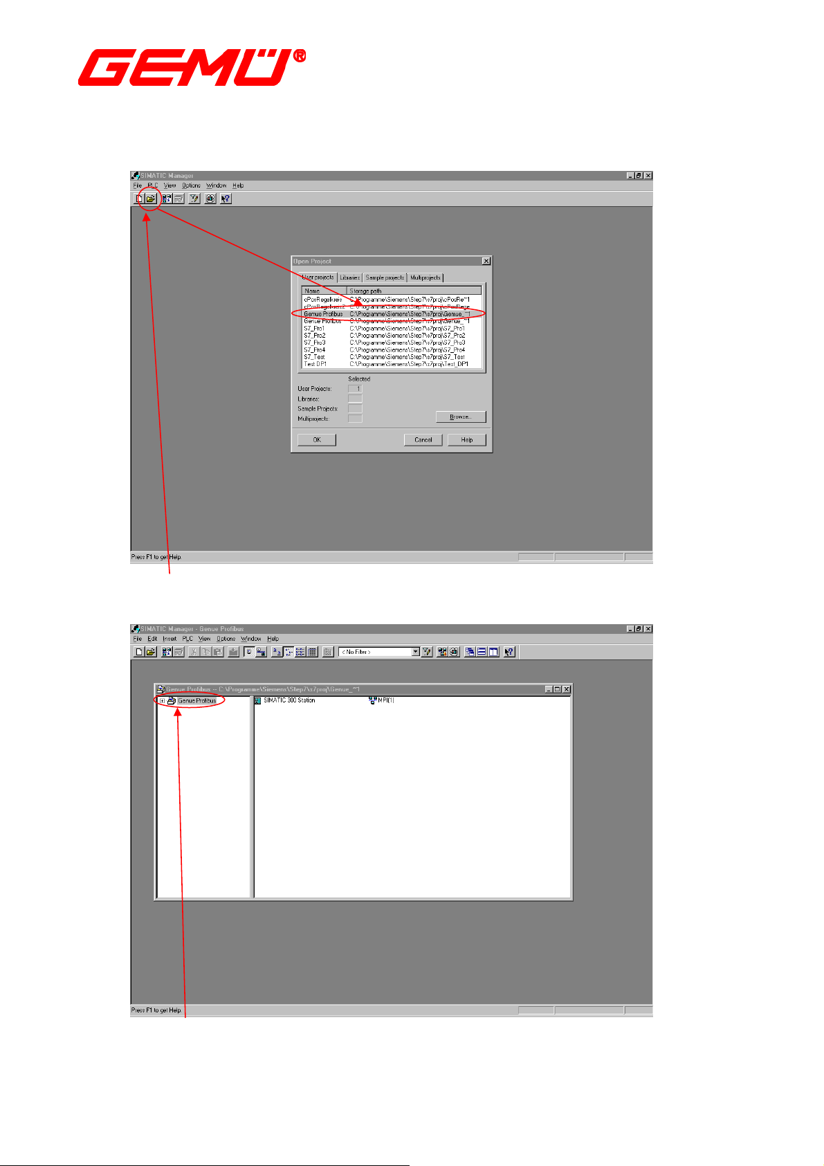
Open new project
Open folder
ACTRONIC
®
Profibus DP Operating instructions
SideStep® Industrial OPEN/CLOSE
25/42
Page 26
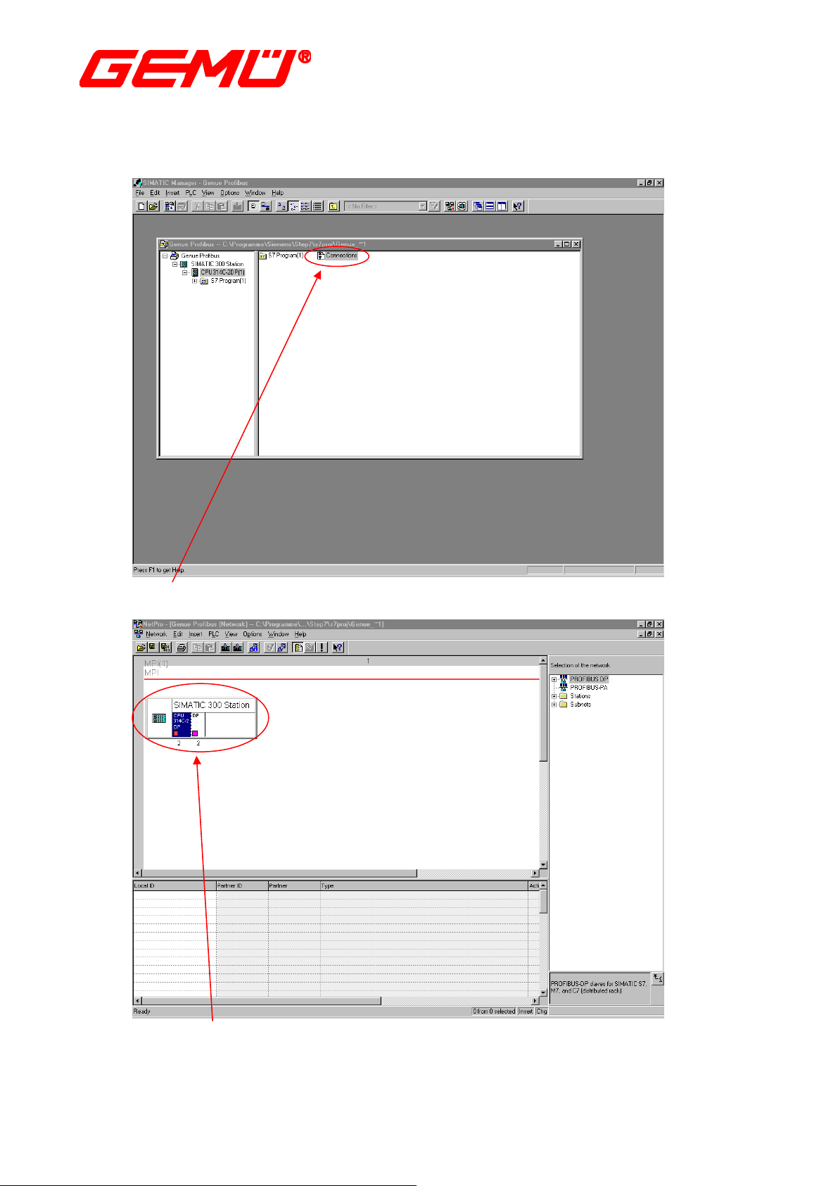
Configure project (double-click)
Activate window with double-click
ACTRONIC
®
Profibus DP Operating instructions
SideStep® Industrial OPEN/CLOSE
26/42
Page 27
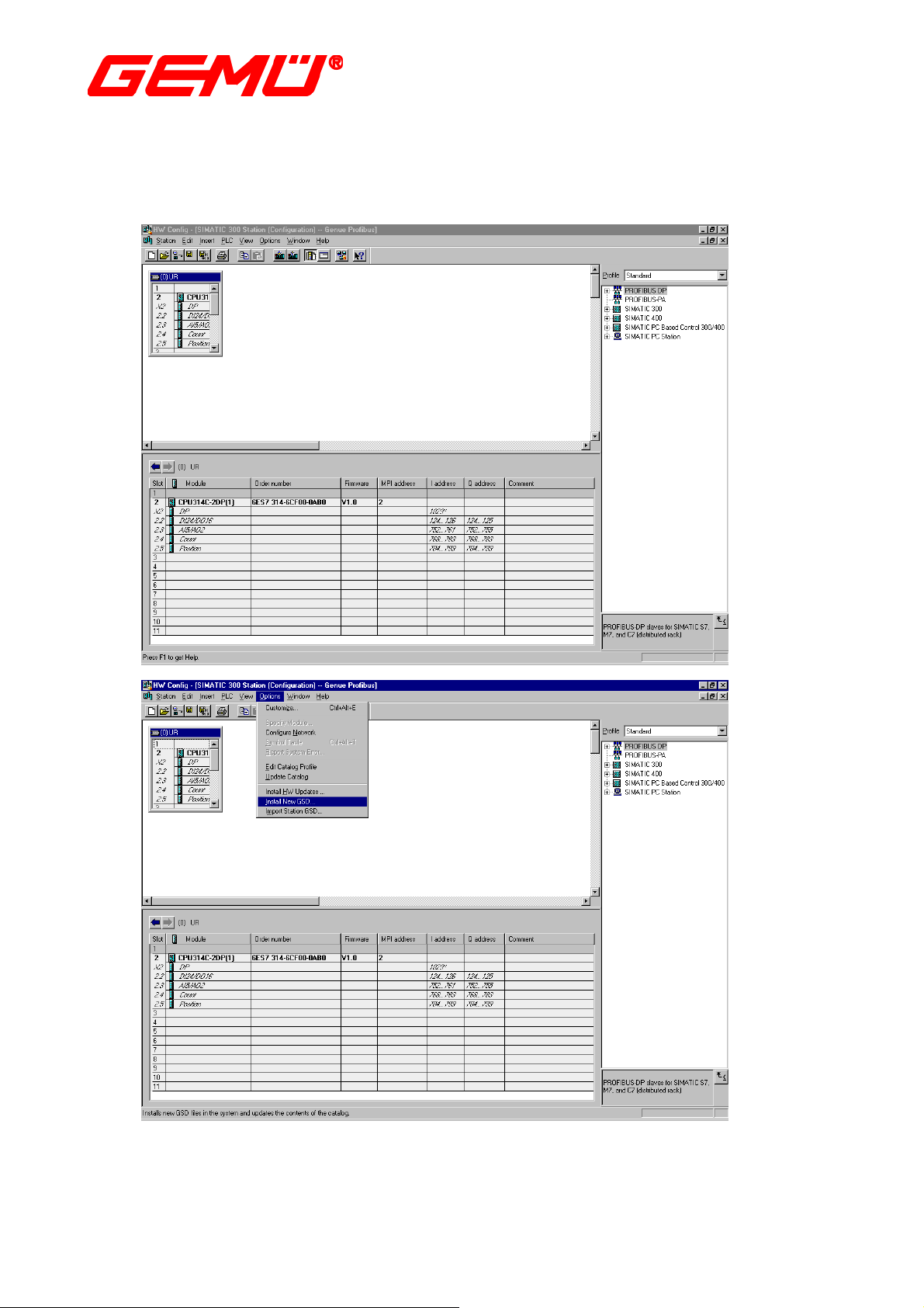
Install new GSD file (G1436a.GSD)
ACTRONIC
®
Profibus DP Operating instructions
SideStep® Industrial OPEN/CLOSE
27/42
Page 28
ACTRONIC
SideStep® Industrial OPEN/CLOSE
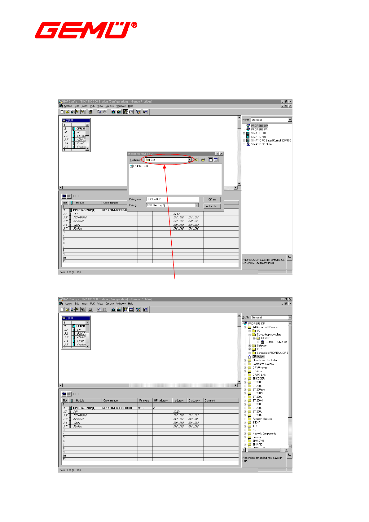
The GSD file is on the CD ROM supplied with every controller
®
Profibus DP Operating instructions
28/42
Page 29
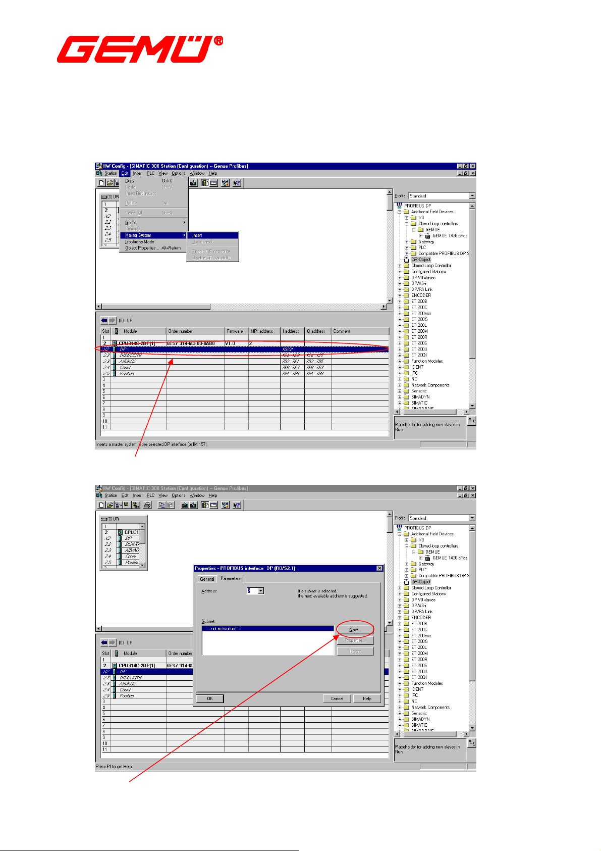
Select “DP“ line
Select “New“
ACTRONIC
®
Profibus DP Operating instructions
SideStep® Industrial OPEN/CLOSE
29/42
Page 30
ACTRONIC
SideStep® Industrial OPEN/CLOSE
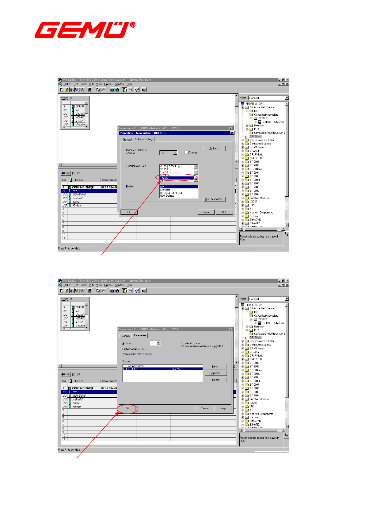
Select transmission speed and confirm with “OK“
Click on “OK“
®
Profibus DP Operating instructions
30/42
Page 31
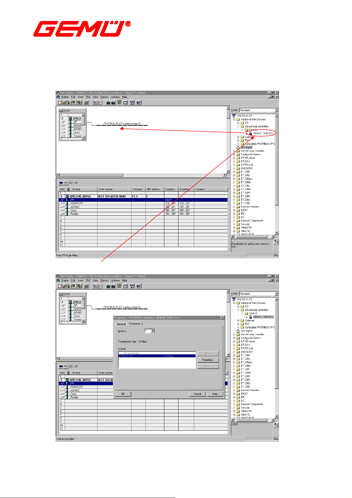
Drag selection into window
ACTRONIC
®
Profibus DP Operating instructions
SideStep® Industrial OPEN/CLOSE
31/42
Page 32
ACTRONIC
®
Profibus DP Operating instructions
SideStep® Industrial OPEN/CLOSE
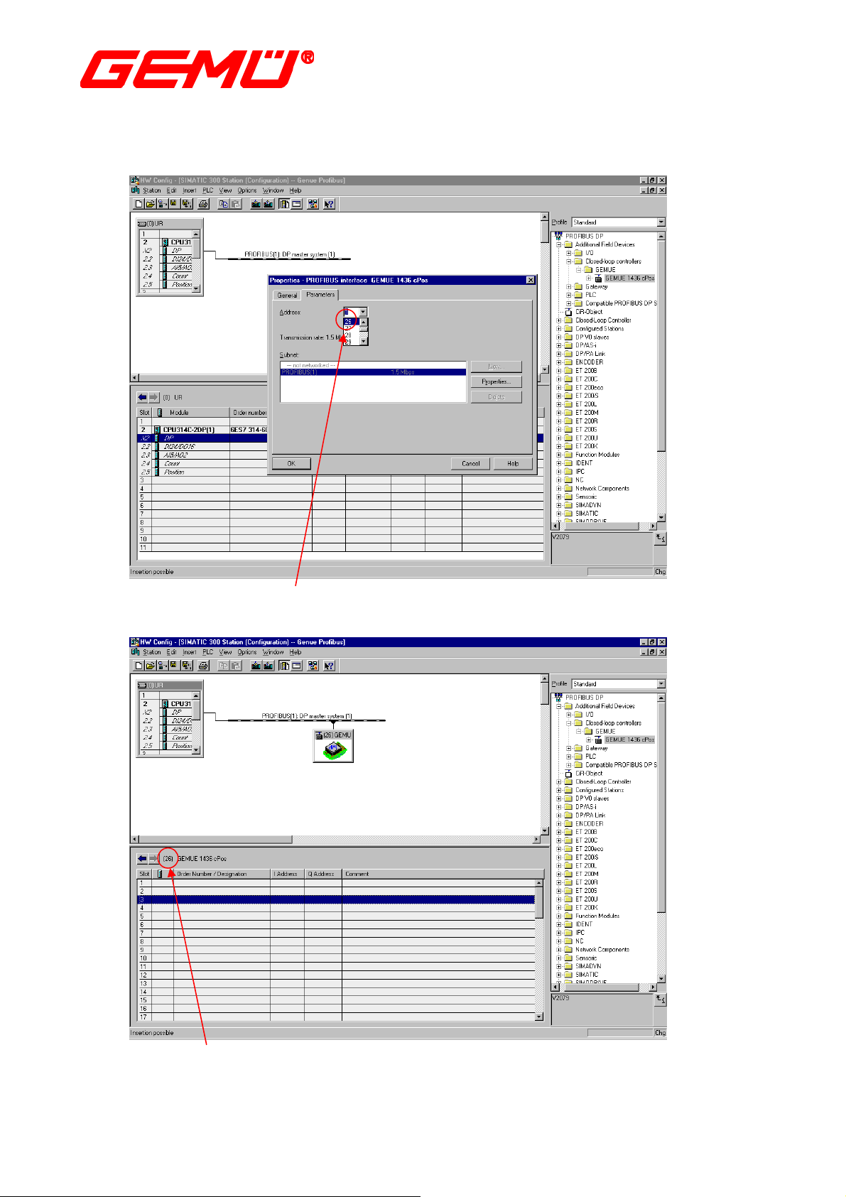
Set the Profibus address of the GEMÜ SideStep (default setting 26)
Set Profibus address (26)
32/42
Page 33
ACTRONIC
®
Profibus DP Operating instructions
SideStep® Industrial OPEN/CLOSE
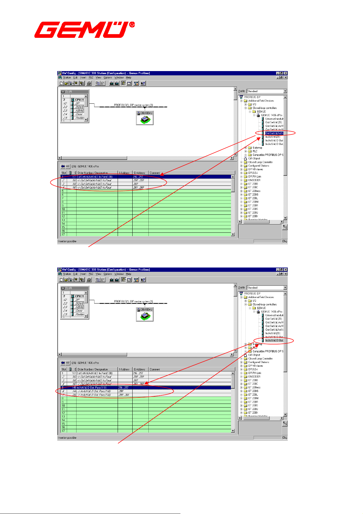
Select outputs (click and drag into table)
ATTENTION! Only 1 configuration
Select inputs (click and drag into table)
ATTENTION! Only 1 configuration
The GEMÜ SideStep identifies the configuration on the basis of the block length. No settings required.
33/42
Page 34
ACTRONIC
®
Profibus DP Operating instructions
SideStep® Industrial OPEN/CLOSE
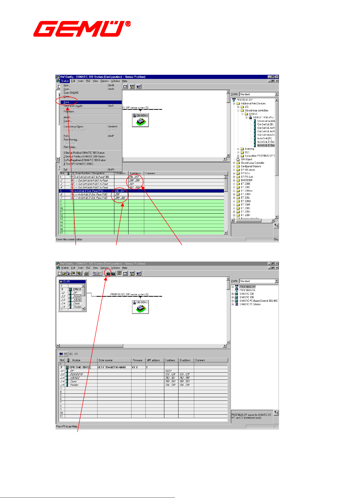
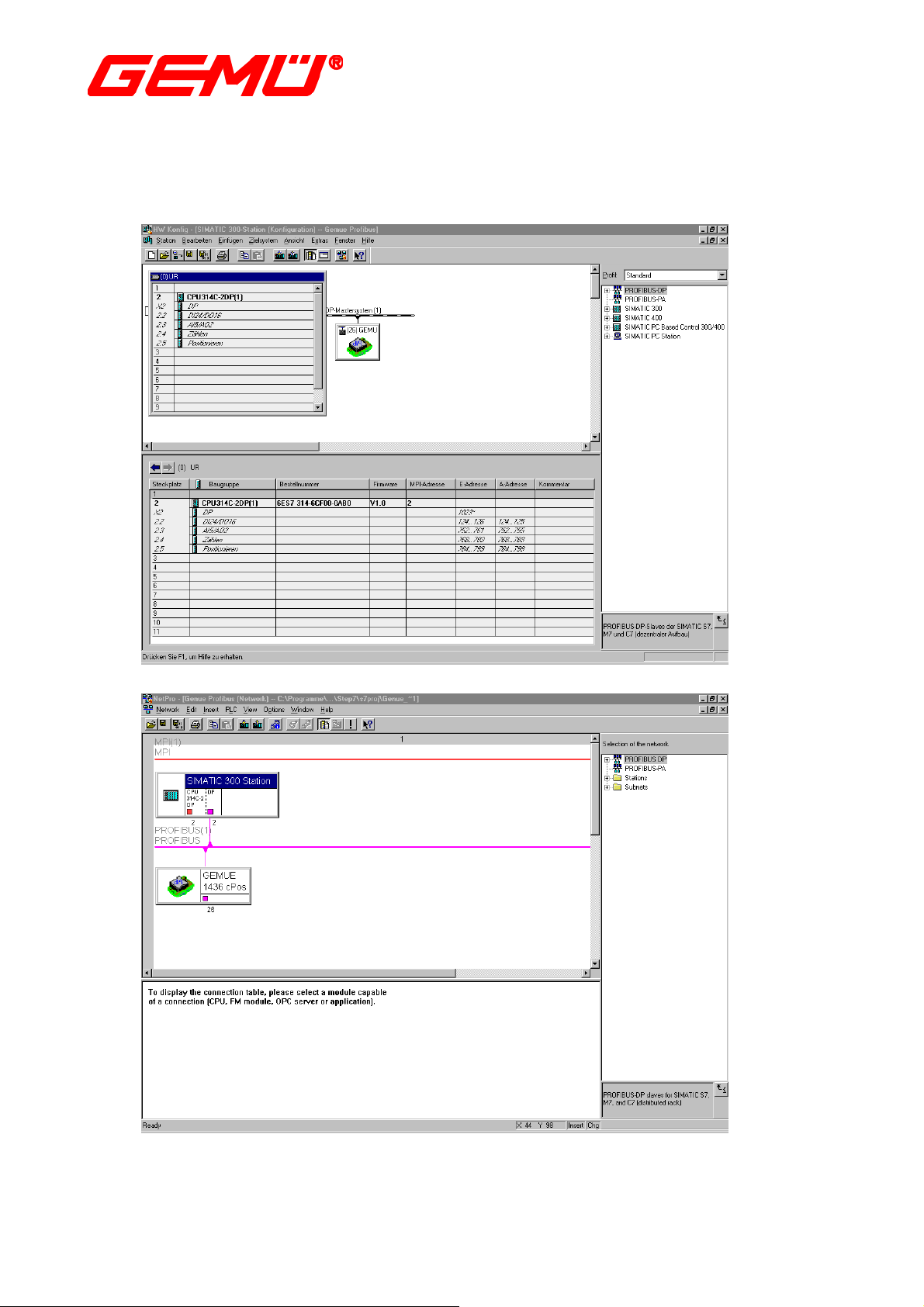
Save settings Input addresses (no action) Output addresses (no action)
Load configuration in PLC.
34/42
Page 35
ACTRONIC
®
Profibus DP Operating instructions
SideStep® Industrial OPEN/CLOSE
35/42
Page 36
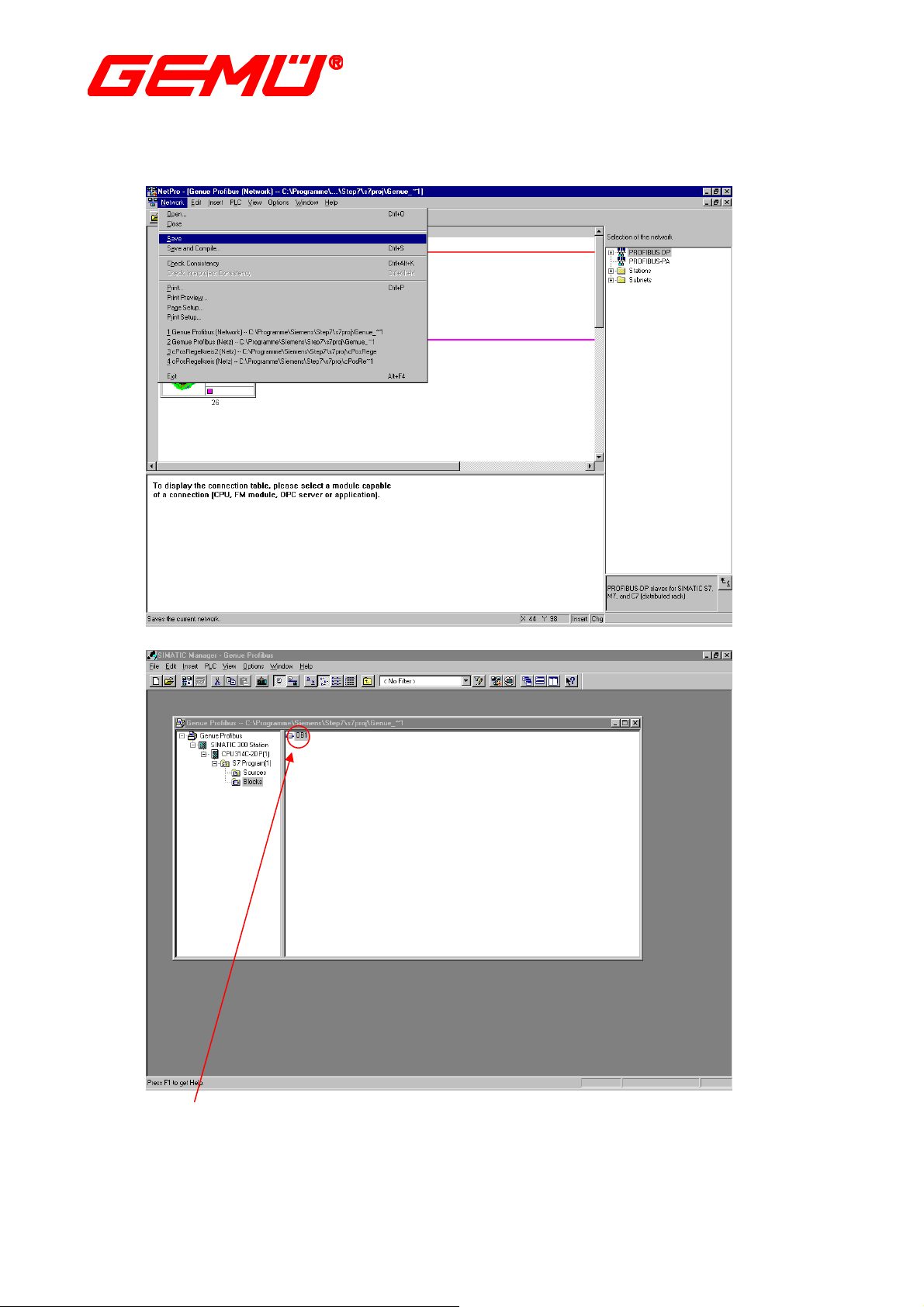
Program OB1
ACTRONIC
®
Profibus DP Operating instructions
SideStep® Industrial OPEN/CLOSE
36/42
Page 37
ACTRONIC
®
Profibus DP Operating instructions
SideStep® Industrial OPEN/CLOSE
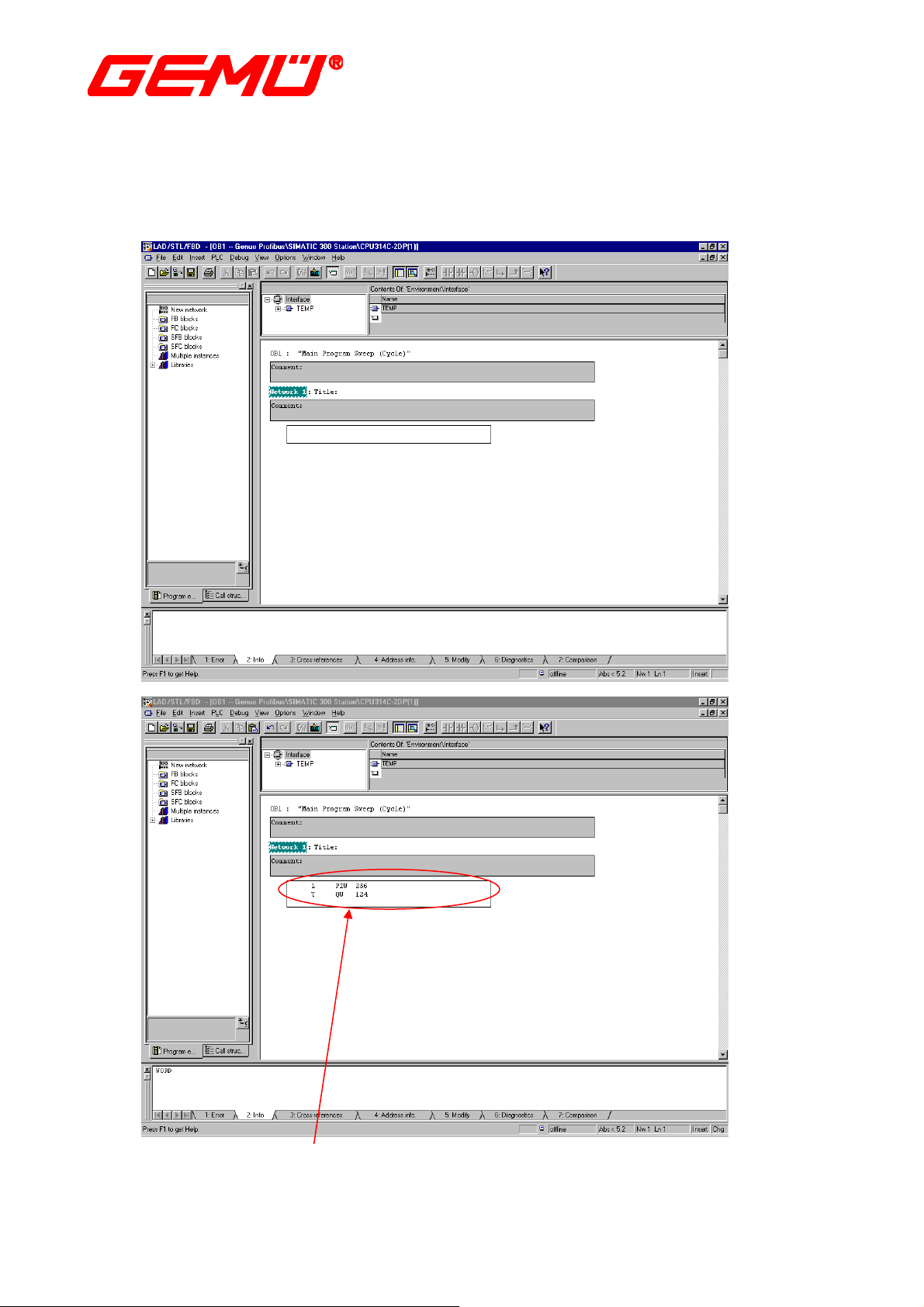
Ex. Input valve position and output to outputs.
ATTENTION! Addresses above 127 must be accessed using PEW, PEB, PAW, PAB....
37/42
Page 38
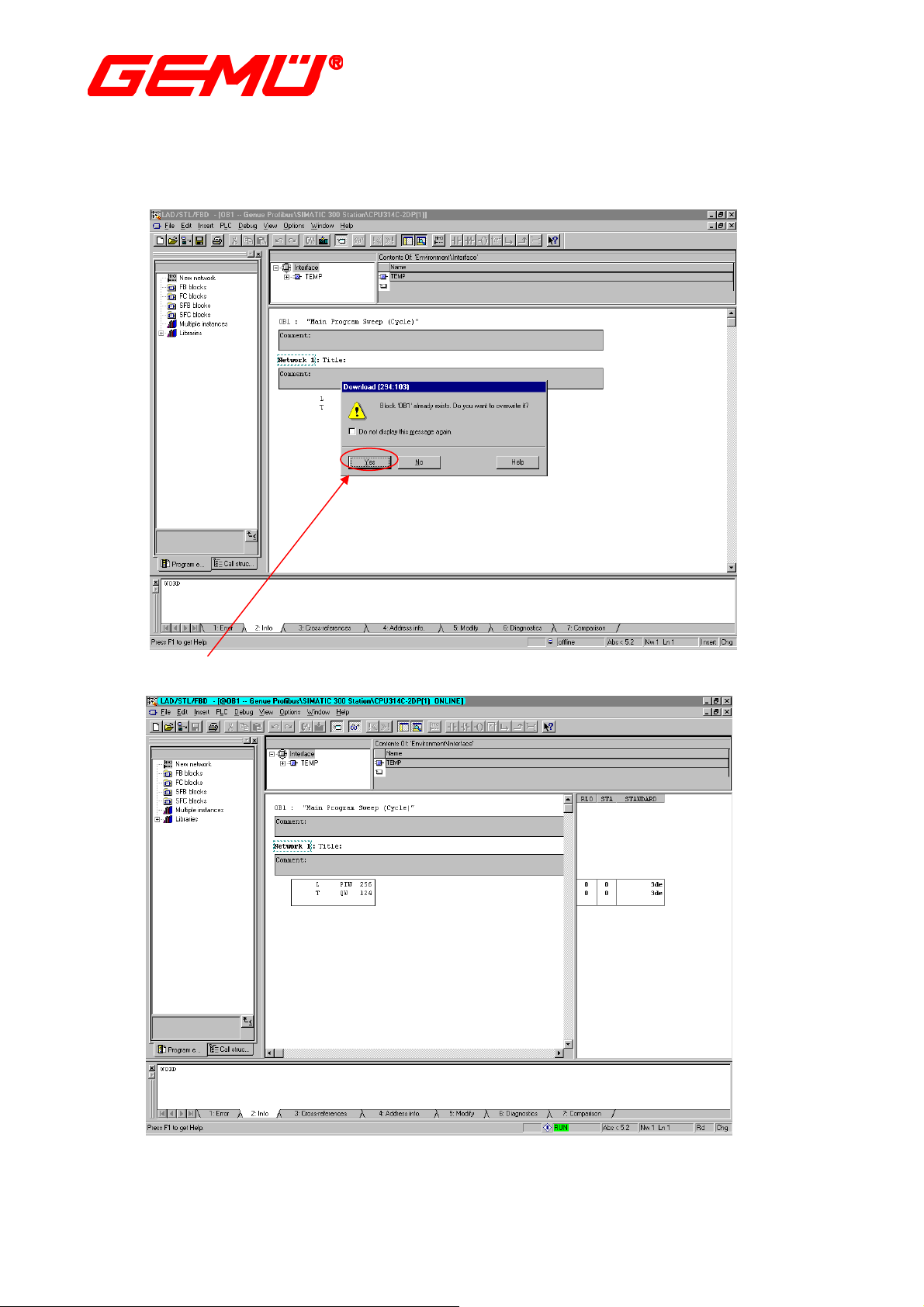
Confirm by clicking on “Yes“
ACTRONIC
®
Profibus DP Operating instructions
SideStep® Industrial OPEN/CLOSE
38/42
Page 39
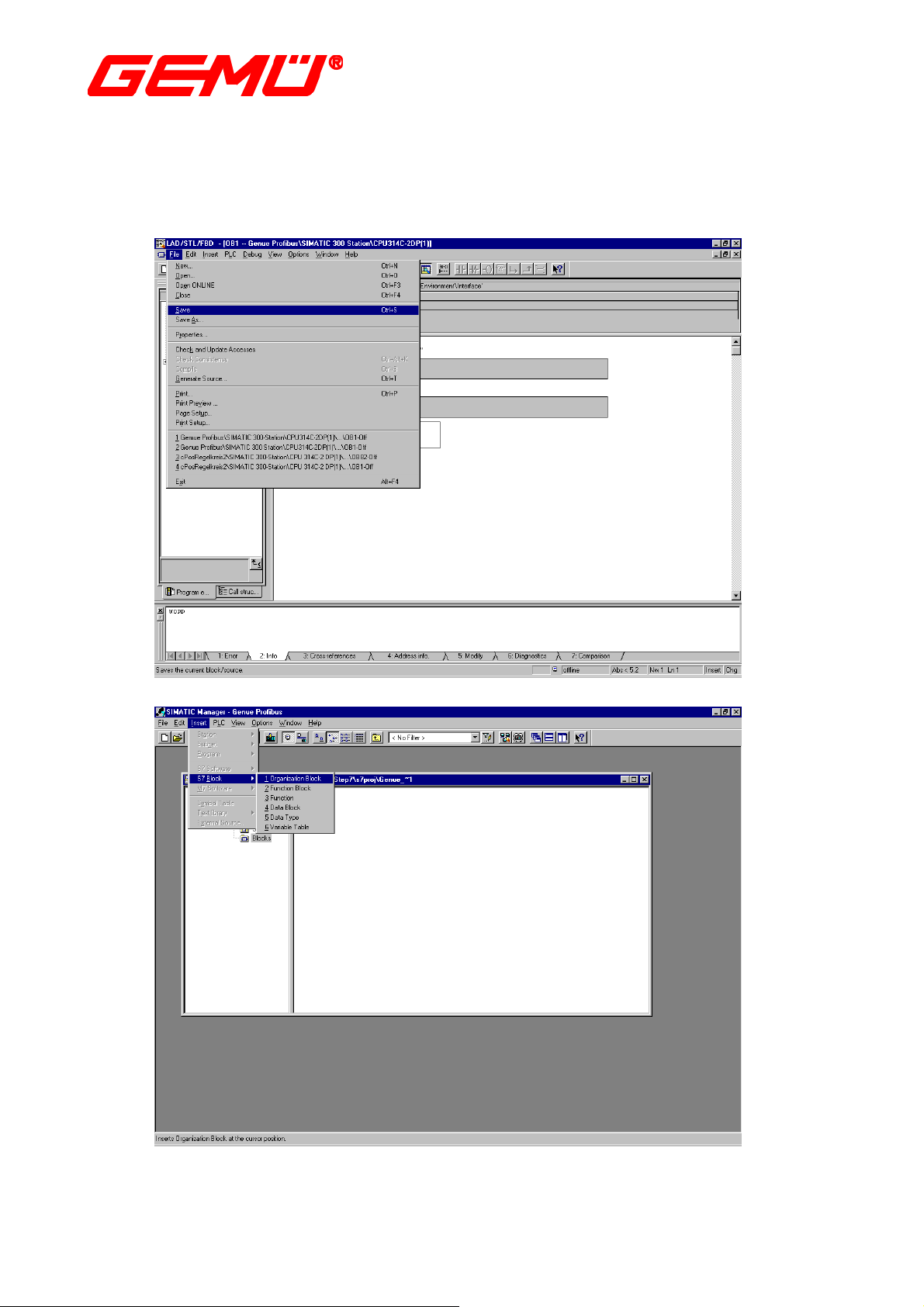
Create new OB
ACTRONIC
®
Profibus DP Operating instructions
SideStep® Industrial OPEN/CLOSE
39/42
Page 40
ACTRONIC
SideStep® Industrial OPEN/CLOSE
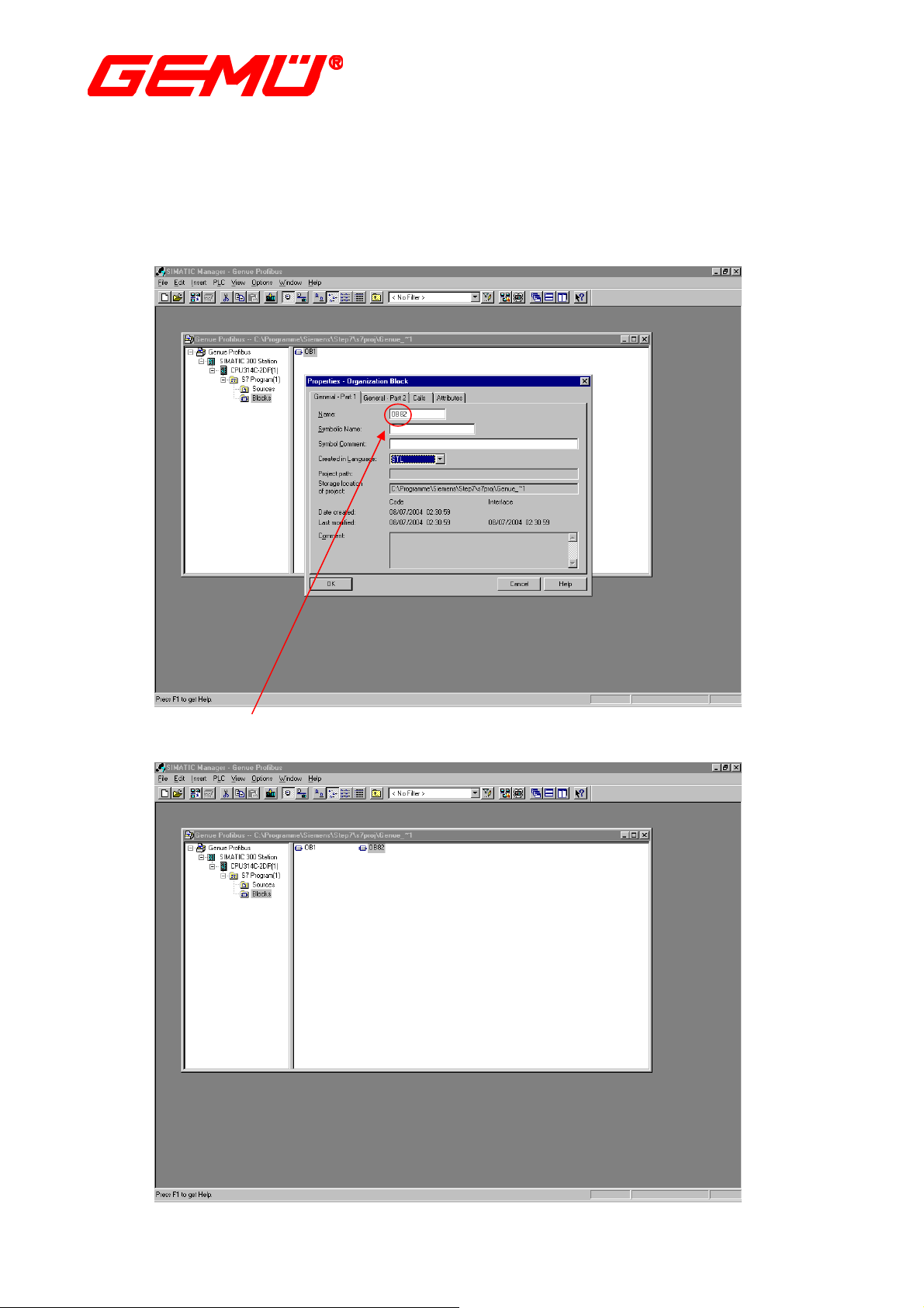
Errors are trapped in organisation module OB82.
ATTENTION! This operation module must be generated.
®
Profibus DP Operating instructions
40/42
Page 41
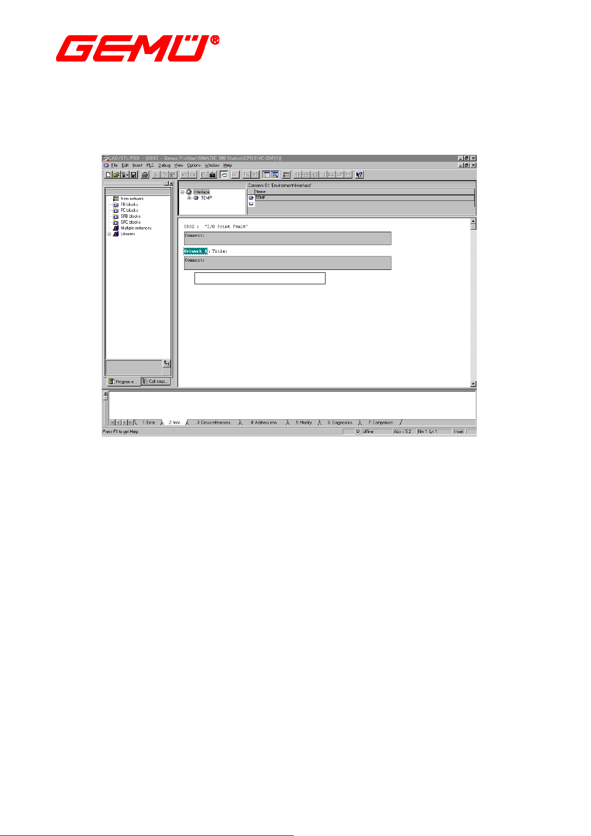
No storage of function required
ACTRONIC
®
Profibus DP Operating instructions
SideStep® Industrial OPEN/CLOSE
41/42
Page 42

ACTRONIC
®
Profibus DP Operating instructions
SideStep® Industrial OPEN/CLOSE
Note concerning the EC Machinery Directive 2006/42/EC:
A Declaration of Incorporation in accordance with the EC Machinery Directive 2006/42/EC
accompanies this product.
For incorporation in an installation classed as a machine:
The commissioning is prohibited until it has been determined that the machine (plant) in
which this product is to be incorporated complies with the provisions of the EC Machinery
Directive 2006/42/EC.
Handling, assembly and commissioning, in addition to setting and adjustment of the
machine must be performed only by authorised specialist staff.
42/42
Subject to technical alterations · 12/2009 · 88290165
 Loading...