

Page 1
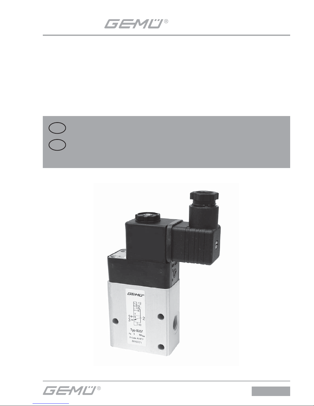
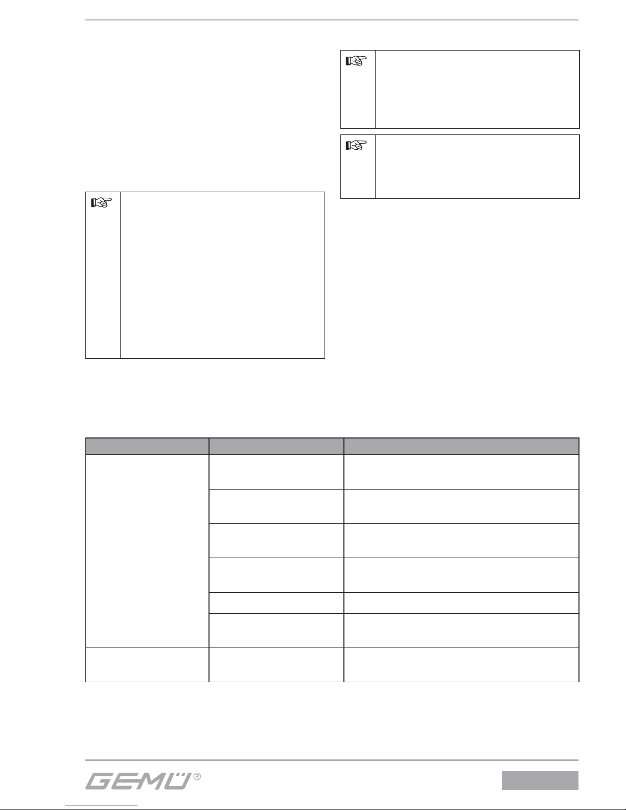
Pilot solenoid valve, metal
3/2-way, electrically controlled
GB
INSTALLATION, OPERATING AND
MAINTENANCE INSTRUCTIONS
8357
8357
Vorsteuer-Magnetventil, Metall
3/2-Wege, elektrisch angesteuert
DE
ORIGINAL EINBAU- UND MONTAGEANLEITUNG
Page 2
8357
2 / 32
1 Allgemeine Hinweise
Voraussetzungen für die einwandfreie
Funktion des GEMÜ-VorsteuerMagnetventils:
Sachgerechter Transport und Lagerung.
Installation und Inbetriebnahme durch
eingewiesenes Fachpersonal.
Betrieb gemäß dieser Einbau- und
Montageanleitung.
Ordnungsgemäße Instandhaltung.
Korrekte Montage, Bedienung und Wartung
oder Reparatur gewährleisten einen
störungsfreien Betrieb des VorsteuerMagnetventils.
Beschreibungen und
Instruktionen beziehen sich auf
Standardausführungen. Für
Sonderausführungen, die in dieser
Einbau- und Montageanleitung
nicht beschrieben sind, gelten die
grundsätzlichen Angaben in dieser
Einbau- und Montageanleitung in
Verbindung mit einer zusätzlichen
Sonderdokumentation.
Alle Rechte wie Urheberrechte
oder gewerbliche Schutzrechte
werden ausdrücklich vorbehalten.
2 Allgemeine
Sicherheitshinweise
Die Sicherheitshinweise in dieser Einbauund Montageanleitung beziehen sich nur
auf das einzelne Vorsteuer-Magnetventil.
In Kombination mit anderen Anlagenteilen
können Gefahrenpotentiale entstehen, die
durch eine Gefahrenanalyse betrachtet
werden müssen.
Für die Erstellung der Gefahrenanalyse,
die Einhaltung daraus resultierender
Schutzmaßnahmen sowie die Einhaltung
regionaler Sicherheitsbestimmungen ist der
Betreiber verantwortlich.
Inhaltsverzeichnis
1 Allgemeine Hinweise 2
2 Allgemeine Sicherheitshinweise 2
2.1 Hinweise für Service- und
Bedienpersonal 3
2.2 Warnhinweise 3
2.3 Verwendete Symbole 4
3 Vorgesehener Einsatzbereich 4
4 Lieferumfang 4
5 Technische Daten 5
6 Bestelldaten 5
7 Transport und Lagerung 6
7.1 Transport 6
7.2 Lagerung 6
8 Funktionsbeschreibung 6
9 Geräteaufbau 6
10 Montage und Betrieb 7
10.1 Montage 7
10.2 Pneumatischer Anschluss 8
10.3 Elektrischer Anschluss 9
10.4 Handnotbetätigung 10
11 Inbetriebnahme 11
12 Inspektion und Wartung 11
12.1 Austausch Magnetspule 12
13 Demontage 12
14 Entsorgung 12
15 Rücksendung 13
16 Hinweise 13
17 Fehlersuche /
Störungsbehebung 13
18 Herstellererklärung 14
19 Konformitätserklärung 15
Page 3
8357
3 / 32
Die Sicherheitshinweise berücksichtigen
nicht:
Zufälligkeiten und Ereignisse, die bei
Montage, Betrieb und Wartung auftreten
können.
die ortsbezogenen
Sicherheitsbestimmungen, für
deren Einhaltung – auch seitens des
hinzugezogenen Montagepersonals – der
Betreiber verantwortlich ist.
2.1 Hinweise für Service- und
Bedienpersonal
Die Einbau- und Montageanleitung enthält
grundlegende Sicherheitshinweise, die bei
Inbetriebnahme, Betrieb und Wartung zu
beachten sind. Nichtbeachtung kann zur
Folge haben:
Gefährdung von Personen durch
elektrische, mechanische und chemische
Einwirkungen.
Gefährdung von Anlagen in der
Umgebung.
Versagen wichtiger Funktionen.
Gefährdung der Umwelt durch Austreten
gefährlicher Stoff e bei Leckage.
Vor Inbetriebnahme:
G Einbau- und Montageanleitung lesen.
G Montage- und Betriebspersonal
ausreichend schulen.
G Sicherstellen, dass der Inhalt der Einbau-
und Montageanleitung vom zuständigen
Personal vollständig verstanden wird.
G Verantwortungs- und
Zuständigkeitsbereiche regeln.
G Wartungs- und Inspektionsintervalle
festlegen.
Bei Betrieb:
G Einbau- und Montageanleitung am
Einsatzort verfügbar halten.
G Sicherheitshinweise beachten.
G Vorsteuer-Magnetventil nur entsprechend
den Leistungsdaten betreiben.
G Wartungsarbeiten bzw. Reparaturen,
die nicht in der Einbau- und
Montageanleitung beschrieben sind,
dürfen nur nach Absprache mit GEMÜ
durchgeführt werden.
G Sicherheitsdatenblätter bzw. die für
die verwendeten Medien geltenden
Sicherheitsvorschriften unbedingt
beachten.
Bei Unklarheiten
Bei nächstgelegener GEMÜ-
Verkaufsniederlassung nachfragen.
2.2 Warnhinweise
Warnhinweise sind, soweit möglich,
nach folgendem Schema gegliedert.
Warnhinweise sind dabei immer mit
einem Signalwort und teilweise auch
mit einem gefahrenspezifi schen Symbol
gekennzeichnet.
SIGNALWORT
Art und Quelle der Gefahr
® Mögliche Folgen bei Nichtbeachtung.
G Maßnahmen zur Vermeidung der
Gefahr.
Folgende Signalwörter bzw.
Gefährdungsstufen werden eingesetzt:
GEFAHR
Unmittelbare Gefahr!
® Bei Nichtbeachtung sind Tod oder
schwerste Verletzungen die Folge.
WARNUNG
Möglicherweise gefährliche Situation!
® Bei Nichtbeachtung drohen schwerste
Verletzungen oder Tod.
VORSICHT
Möglicherweise gefährliche Situation!
® Bei Nichtbeachtung drohen mittlere bis
leichte Verletzungen.
VORSICHT (OHNE SYMBOL)
Möglicherweise gefährliche Situation!
® Bei Nichtbeachtung drohen
Sachschäden.
Page 4
8357
4 / 32
2.3 Verwendete Symbole
Hand:
Beschreibt allgemeine Hinweise
und Empfehlungen.
G
Punkt:
Beschreibt auszuführende
Tätigkeiten.
®
Pfeil:
Beschreibt Reaktion(en) auf
Tätigkeiten.
Aufzählungszeichen
3 Vorgesehener
Einsatzbereich
GEFAHR
Explosionsgefahr!
® Gefahr von schwersten Verletzungen
oder Tod!
G Der Einsatz des Vorsteuer-
Magnetventils in explosionsgefährdeten
Bereichen ist nicht zulässig.
G ATEX-Ausführung: Das
Vorsteuer-Magnetventil darf nur
in explosionsgefährdeten Zonen
verwendet werden, die auf der
Konformitätserklärung (ATEX) bestätigt
wurden.
WARNUNG
Vorsteuer-Magnetventil nur
bestimmungsgemäß verwenden!
® Sonst erlischt Herstellerhaftung und
Gewährleistungsanspruch.
G Vorsteuer-Magnetventile
ausschließlich entsprechend den in
der Vertragsdokumentation und in
der Einbau- und Montageanleitung
festgelegten Betriebsbedingungen
verwenden.
Das Vorsteuer-Magnetventil GEMÜ 8357
ist zur Ansteuerung von doppelt
wirkenden pneumatischen Zylinderund Membranantrieben oder anderen
pneumatisch betätigten Stellgliedern
konzipiert.
Das Vorsteuer-Magnetventil darf nur
gemäß den technischen Daten eingesetzt
werden (siehe Kapitel 5 „Technische
Daten“).
Schrauben und Kunststoff teile am
Vorsteuer-Magnetventil nicht lackieren!
Durch eine geeignete elektrische
Beschaltung der VorsteuerMagnetventile sicherstellen, dass
die Grenzwerte der harmonisierten
Normen EN 6100-6-3 und EN 61006-1 eingehalten werden und
damit die Richtlinie 2004/108/EG
(Elektromagnetische Verträglichkeit)
erfüllt ist.
Das Vorsteuer-Magnetventil
entspricht Artikel 4, Absatz 3 der
Druckgeräterichtlinie (DGRL)
2014/68/EU. Das bedeutet, dass
die Auslegung und Herstellung
nach der im Mitgliedsstaat
geltenden guten Ingenieurspraxis
erfolgt. Die CE-Kennzeichnung
am Vorsteuer-Magnetventil
bezieht sich nicht auf die
DGRL. Somit entfällt auch die
Konformitätserklärung nach dieser
Richtlinie.
4 Lieferumfang
Das Vorsteuer-Magnetventil wird als
separat verpacktes Bauteil ausgeliefert. Die
Innengewinde sind mit Verschlusskappen
verschlossen.
Im Lieferumfang sind enthalten:
Vorsteuer-Magnetventil mit Magnetspule
Gerätesteckdose
Page 5
8357
5 / 32
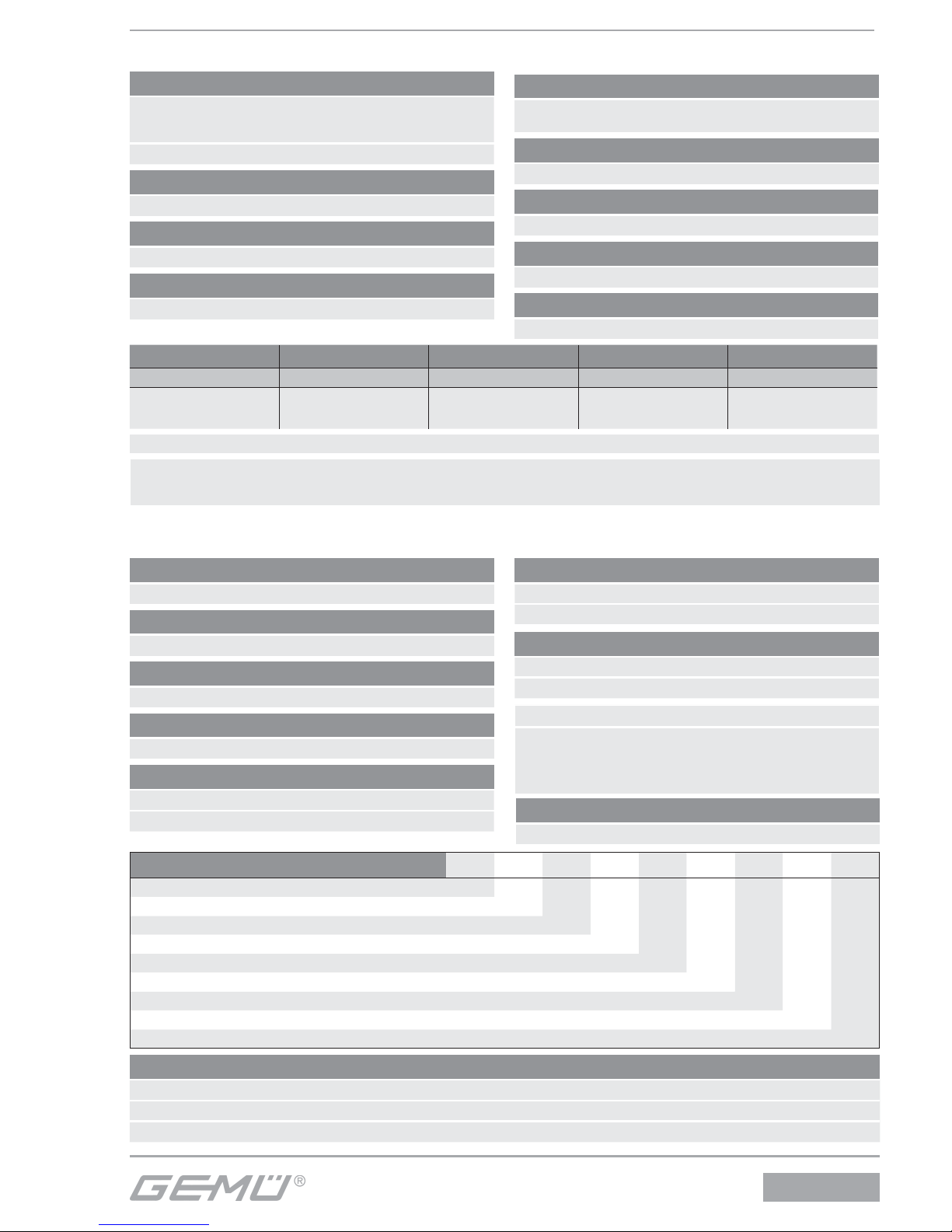
5 Technische Daten
Beschaltungshinweis:
besondere Beschaltungen auf Anfrage. Bei Verwendung von elektronischen Schaltern und Zusatzbeschaltung ist zu beachten,
dass unzulässige Restströme durch geeignete Auslegung vermieden werden.
Nennweite Betriebsdruck Durchflusswert Bemerkung Gewicht
[DN] [bar]
[l/min]
[kg]
6 1,0 - 10
1200*
Rücklauf R nicht
drosselbar
0,4
* 6 bar Druck 1 bar ∆p
Betriebsmedium
Gefilterte, geölte oder ölfreie Druckluft, die die physikalischen und chemischen Eigenschaften des jeweiligen
Gehäuse- und Dichtwerkstoffes nicht negativ beeinflusst.
Zul. Temp. des Betriebsmediums -10...+60 °C
Schaltzeit
ca. 20 ms
Schutzart
IP 65 (Ex-Ausführung auf Anfrage)
Leistungsaufnahme
Wechselstrombetrieb 4,9 VA
Gleichstrombetrieb 2,7 W
Einschaltdauer
100 % ED
Alternative Ausführungen
Ausführung nach ATEX
Zulässige Spannungsabweichung
±10 nach VDE 0580
Einbaulage
Beliebig
Durchfl ussrichtung
Festgelegt
6 Bestelldaten
Bestellbeispiel
8357 6 M 1 14 2 1 230 50
Typ 8357
Nennweite 6
Gehäuseform (Code) M
Anschlussart (Code) 1
Ventilkörperwerkstoff (Code) 14
Dichtwerkstoff (Code) 2
Steuerfunktion 1
Anschlussspannung (Code) 230
Netzfrequenz (Code) 50
Verfügbarkeiten Spannung/Frequenz
AC 24 V AC 50 Hz
230 V AC 50 Hz
DC 24 V DC -
Weitere Spannungen auf Anfrage
Anschlussspannung Code
24 V 24
230 V 230
Netzfrequenz Code
50 Hz 50
DC DC
Gehäuseform Code
Mehrwege M
Anschlussart Code
Gewindemuffe DIN ISO 228 1
Ventilkörperwerkstoff Code
Aluminium 14
Dichtwerkstoff Code
Perbunan (NBR) 2
Schaltstellung Code
Sperr-Nullstellung 1
Durchfluss-Nullstellung 2
Bestellhinweis
Passende Gerätesteckdose nach DIN EN 175301-803 Form A, Gerätesteckdose lose: Typ GEMÜ 1220/1221
Direktanbau an Ventile mit G 1/4“-Gewinde mit Doppelnippel Typ GEMÜ 1755
Ohne Stecker K.-Nr. 1007, in Ex-Ausführung K.-Nr. 6491
Sonderfunktion Code
ATEX-Ausführung X
Page 6
8357
6 / 32
7 Transport und Lagerung
7.1 Transport
G Vorsteuer-Magnetventil nur auf
geeignetem Lademittel transportieren,
nicht stürzen, vorsichtig handhaben.
G Verpackungsmaterial entsprechend
den Entsorgungsvorschriften /
Umweltschutzbestimmungen entsorgen.
7.2 Lagerung
G Vorsteuer-Magnetventil trocken und
staubgeschützt in Originalverpackung
lagern.
G Vorsteuer-Magnetventil nur mit
verschlossenen Anschlüssen lagern.
G UV-Strahlung und direkte
Sonneneinstrahlung vermeiden.
G Bei Einlagerung über einen längeren
Zeitraum Lagertemperaturen von
-10 °C bis +20 °C nicht überschreiten.
Erhöhte Lagertemperaturen können
bei Dichtungswerkstoff en zu einer
Verkürzung der Lebensdauer führen.
G Lösungsmittel, Chemikalien, Säuren,
Kraftstoff e u.ä. dürfen nicht mit Ventilen
und deren Ersatzteilen in einem Raum
gelagert werden.
8 Funktionsbeschreibung
Das fremdgesteuerte 3/2-Wege-VorsteuerMagnetventil ist indirekt angesteuert. Das
Gehäuse besteht aus Aluminium. Der
Magnetantrieb ist mit Kunststoff ummantelt
und abnehmbar. Der T-Ring-Kolbenschieber
besitzt eine weiche Elastomerdichtung.
Das Vorsteuer-Magnetventil verfügt über
eine Handnotbetätigung. Der elektrische
Anschluss erfolgt über eine mitgelieferte
Gerätesteckdose nach DIN EN 175301-803
Form A.
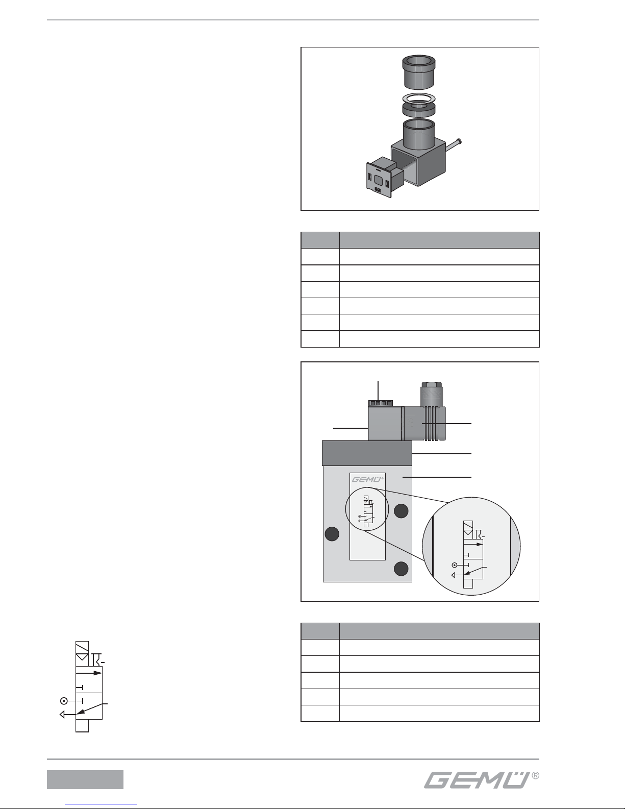
Schaltstellung:
2
10
12
1
3
9 Geräteaufbau
1
2
3
4
5
6
Gerätesteckdose
Pos. Benennung
1 Schraube
2 Gerätesteckdose
3 Klemmblock
4 Druckring
5 Dichtring
6 Kabeleinführung
Typ 8357
7
2
8
9
2
10
12
1
3
2
10
12
1
3
10
Geräteaufbau
Pos. Benennung
2 Gerätesteckdose
7 Befestigungsmutter
8 Handnotbetätigung
9 Ventilkörper
10 Magnetspule
Page 7
8357
7 / 32
10 Montage und Betrieb
GEFAHR
Gefahr durch Stromschlag!
® Verletzungen oder Tod (bei
Betriebsspannungen größer
als Schutzkleinspannungen)
drohen!
G Bei Arbeiten am Vorsteuer-
Magnetventil Stromversorgung
unterbrechen und gegen
Wiedereinschalten sichern.
VORSICHT
Funktionsstörung des VorsteuerMagnetventils durch verschmutzte
Medien!
® Vorsteuer-Magnetventil öff net
oder schließt bei verstopften
Steuerbohrungen oder durch Schmutz
blockiertem Anker nicht mehr.
G Rohrleitungssystem vor Einbau des
Vorsteuer-Magnetventils reinigen.
G Bei verschmutzten Medien
Schmutzfänger mit
Maschenweite ≤ 0,25 mm vor
Ventileingang montieren.
G Vorsteuer-Magnetventil mindestens
einmal im Monat schalten.
VORSICHT
Zerstörung des VorsteuerMagnetventils durch gefrierfähiges
Medium!
® Das Vorsteuer-Magnetventil ist nicht
frostsicher.
G Vorsteuer-Magnetventil mit
gefrierfähigen Medien nur oberhalb des
Gefrierpunktes betreiben.
VORSICHT
Gefahr durch Durchströmung entgegen
der Durchfl ussrichtung!
® Beschädigung des Vorsteuer-
Magnetventils.
G Vorsteuer-Magnetventil nur in
Durchfl ussrichtung betreiben.
G Bei zu erwartenden rückwärtigen
Strömungen entsprechende
Vorkehrungen treff en (z. B.
Rückschlagventil).
10.1 Montage
Vor Einbau:
G Eignung des Vorsteuer-Magnetventils
vor Einbau prüfen!
Siehe Kapitel 5 “Technische Daten”.
WARNUNG
Unter Druck stehende Armaturen!
® Gefahr von schwersten Verletzungen
oder Tod!
G Nur an druckloser Anlage arbeiten.
VORSICHT
Magnetspule nicht als Hebel
verwenden!
® Beschädigung der Magnetspule oder
Magnethülse!
G Zum Aufschrauben des Vorsteuer-
Magnetventils auf die Rohrleitung
nur vorgesehene Schlüsselfl ächen
benutzen.
VORSICHT
Spannungen im Ventilkörper!
® Beschädigung des Ventilkörpers.
G Vorsteuer-Magnetventil nur in
fl uchtende Rohrleitungen einbauen.
G Montagearbeiten nur durch geschultes
Fachpersonal durchführen.
G Geeignete Schutzausrüstung gemäß
den Regelungen des Anlagenbetreibers
berücksichtigen.
Page 8
8357
8 / 32
Installationsort:
VORSICHT
G Vorsteuer-Magnetventil äußerlich nicht
stark beanspruchen.
Batteriemontage mit zentraler
Zuluft möglich.
Einbaulage: beliebig.
Handnotbetätigung und elektrischer
Stecker müssen zugänglich bleiben.
Montage:
1. Eignung des Ventils für jeweiligen
Einsatzfall sicherstellen. Das Ventil
muss für die Betriebsbedingungen
des Rohrleitungssystems (Medium,
Mediumskonzentration, Temperatur
und Druck) sowie die jeweiligen
Umgebungsbedingungen geeignet sein.
Technische Daten des Ventils und der
Werkstoff e prüfen.
2. Anlage bzw. Anlagenteil stilllegen.
3. Gegen Wiedereinschalten sichern.
4. Anlage bzw. Anlagenteil drucklos
schalten.
5. Anlage bzw. Anlagenteil vollständig
entleeren und abkühlen lassen bis
Verdampfungstemperatur des Mediums
unterschritten ist und Verbrühungen
ausgeschlossen sind.
6. Ggf. Anlage bzw. Anlagenteil fachgerecht
dekontaminieren, spülen und belüften.
7. Ggf. Schmutzfänger vor Ventileingang
montieren.
8. Verschlusskappen vorsichtig aus
den Innengewinden des VorsteuerMagnetventils lösen.
9. Vorsteuer-Magnetventil mit zwei
Schrauben an entsprechendes Gerät
schrauben.
10. Steuermediumleitungen anschließen
(siehe Kapitel 10.2 „Pneumatischer
Anschluss“).
11. Kabel anschließen (siehe Kapitel 10.3
„Elektrischer Anschluss“).
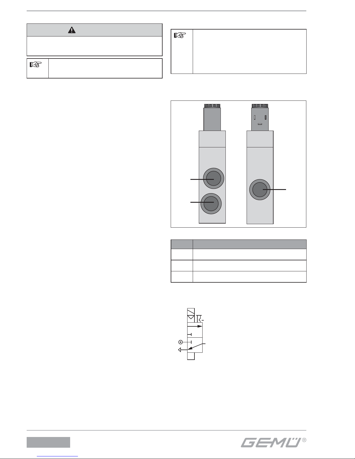
10.2 Pneumatischer Anschluss
Steuermediumleitungen
spannungs- und knickfrei
montieren! Je nach Anwendung
geeignete Anschlussstücke
verwenden.
Gewinde der Steuermediumanschlüsse:
G1/4
1
3
2
Anschlüsse
Pos. Benennung
1 Zuluft
2 Ausgang
3 Abluft
Schaltstellung:
2
10
12
1
3
Page 9
8357
9 / 32
10.3 Elektrischer Anschluss
GEFAHR
Gefahr durch Stromschlag!
® Verletzungen oder Tod (bei
Betriebsspannungen größer
als Schutzkleinspannungen)
drohen!
G Elektrischen Anschluss nur
durch Elektro-Fachkraft
durchführen lassen.
G Kabel vor elektrischem
Anschluss spannungsfrei
schalten.
Jedem Ventilmagnet muss als
Kurzschlusssicherung eine
seinem Bemessungsstrom
entsprechende Sicherung (max.
3-facher Bemessungsstrom nach
DIN 41571 oder IEC 60127-2-1)
bzw. ein Motorschutzschalter mit
Kurzschluss- und thermischer
Schnellauslösung (Einstellung auf
Bemessungsstrom) vorgeschaltet
werden. Diese Sicherung darf im
zugehörigen Versorgungsgerät
untergebracht sein oder muss
separat vorgeschaltet werden. Die
Sicherungs-Bemessungsspannung
muss gleich oder größer als die
angegebene Nennspannung
des Magneten sein. Das
Ausschaltvermögen des
Sicherungssatzes muss gleich
oder größer als der maximal
anzunehmende Kurzschlussstrom
am Einbauort (üblicherweise
1500 A) sein.
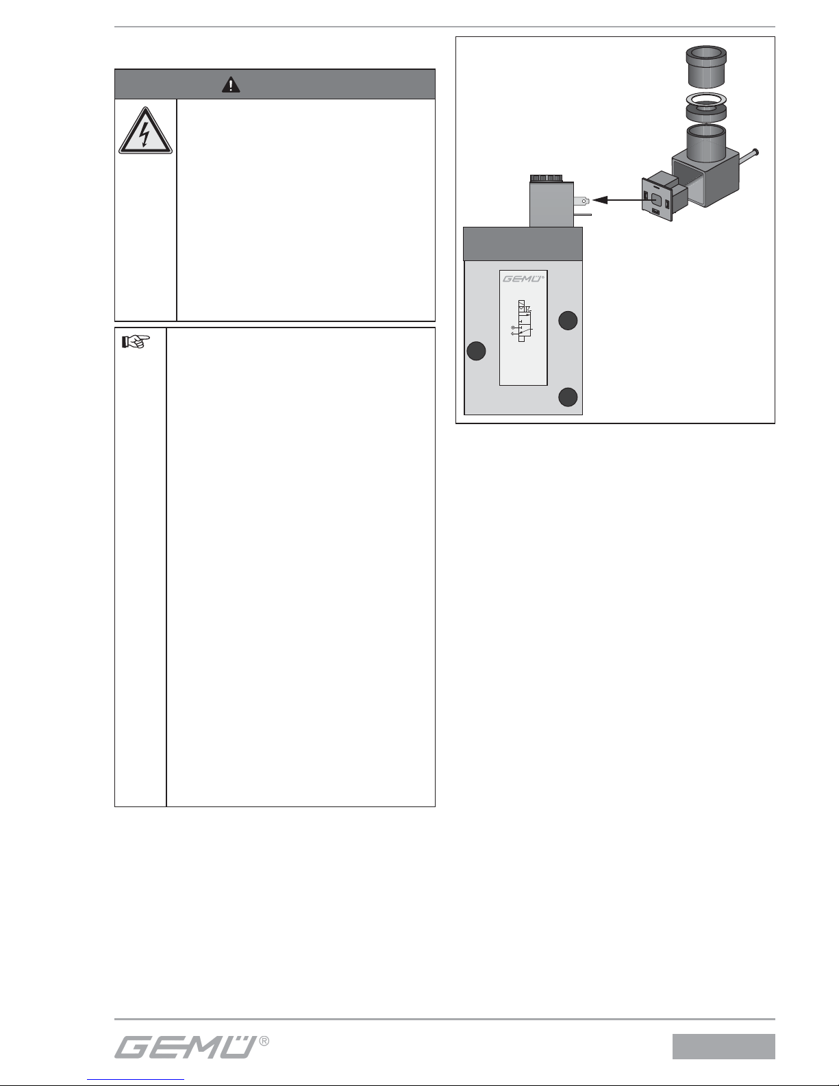
1
2
3
4
5
6
Typ 8357
2
10
12
1
3
Elektrischer Anschluss
1. Anlage spannungsfrei schalten.
2. Zentrische Schraube 1 herausdrehen.
3. Gerätesteckdose 2 mit Klemmenblock 3
von Antriebselement abziehen.
4. Klemmenblock 3 vorsichtig aus
Gerätesteckdose 2 herausdrücken.
5. Kabeleinführung 6 herausschrauben.
6. Druckring 4 und Dichtring 5
herausnehmen.
7. Kabel durch Kabeleinführung 6,
Druckring 4, Dichtring 5 und
Gerätesteckdose 2 einführen.
Page 10
8357
10 / 32
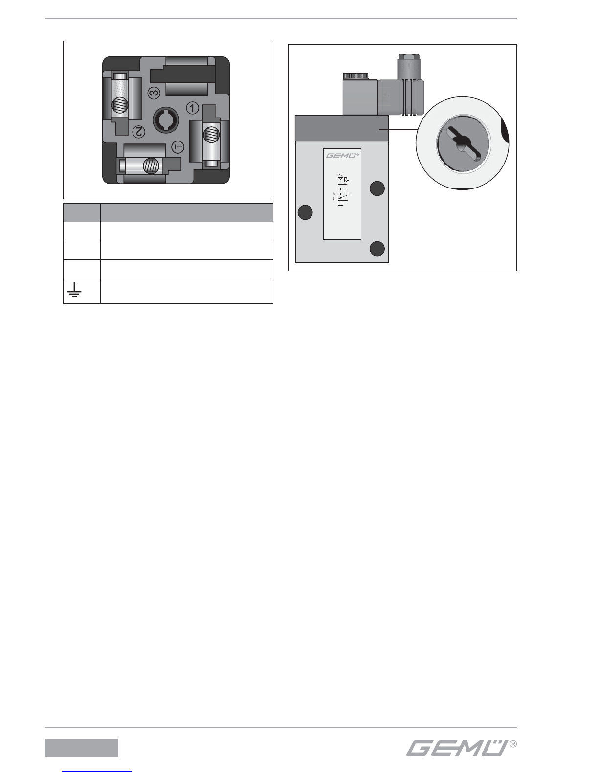
8. Kabel anschließen.
Pos. Benennung
1 Versorgungsspannung
2 Versorgungsspannung
3 nicht belegt
Erdung
9. Dichtring 5 und Druckring 4 in
Gerätesteckdose 2 schieben.
10. Klemmenblock 3 wieder in
Gerätesteckdose 2 einführen bis er
hörbar einrastet.
11. Mit zentrischer Schraube 1
Gerätesteckdose 2 an Antriebselement
festschrauben (max. 0,3 Nm).
12. Kabeleinführung 6 festschrauben.
10.4 Handnotbetätigung
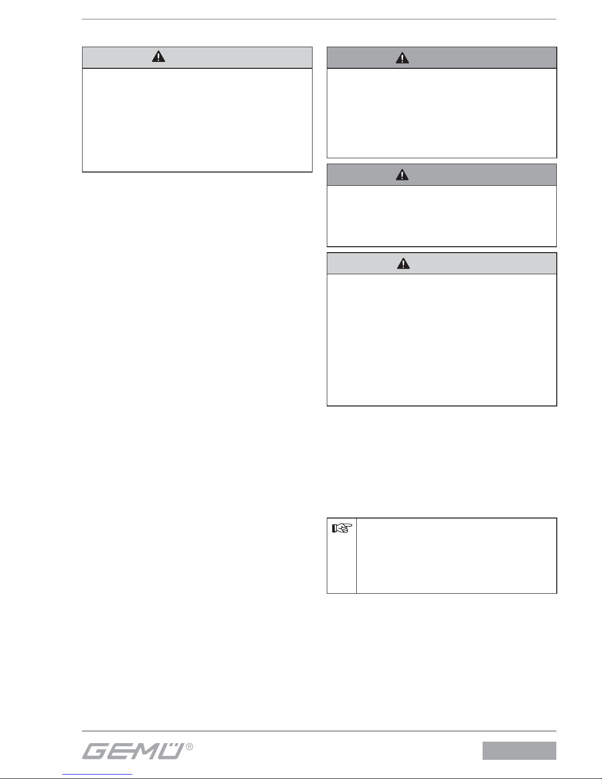
Typ 8357
2
10
12
1
3
1
0
8
Handnotbetätigung
Die Vorsteuer-Magnetventile sind mit einer
Handnotbetätigung 8 ausgestattet.
Handnotbetätigung nur im Störungsfall
betätigen!
Ventil über Handnotbetätigung
betätigen:
G Drehschraube mit Schraubendreher auf
Position 1 drehen (bis Anschlag).
Ventil über Handnotbetätigung
schließen:
G Drehschraube mit Schraubendreher auf
Position 0 drehen (bis Anschlag).
Page 11
8357
11 / 32
11 Inbetriebnahme
VORSICHT
Gegen Leckage vorbeugen!
G Vor Inbetriebnahme Dichtheit der
Medienanschlüsse prüfen!
G Schutzmaßnahmen gegen
Überschreitung des maximal zulässigen
Druckes durch eventuelle Druckstöße
vorsehen.
Vor Reinigung bzw. vor Inbetriebnahme
der Anlage:
G Vorsteuer-Magnetventil auf Dichtheit und
Funktion prüfen.
G Bei neuen Anlagen und nach
Reparaturen Leitungssystem bei
geöff netem Vorsteuer-Magnetventil
durchblasen (zum Entfernen schädlicher
Fremdstoff e).
Reinigung
Der Betreiber der Anlage ist
verantwortlich für Auswahl des
Reinigungsmediums und Durchführung
des Verfahrens.
12 Inspektion und Wartung
WARNUNG
Verbrennungsgefahr durch heiße
Oberfl ächen!
® Magnetspule erhitzt sich in Betrieb auf
bis zu 120 °C.
G Magnetspule und Rohrleitung vor
Wartungsarbeiten abkühlen lassen.
WARNUNG
Unter Druck stehende Armaturen!
® Gefahr von schwersten Verletzungen
oder Tod!
G Nur an druckloser Anlage arbeiten.
VORSICHT
G Wartungs- und
Instandhaltungstätigkeiten nur durch
geschultes Fachpersonal.
G Für Schäden welche durch
unsachgemäße Handhabung oder
Fremdeinwirkung entstehen, übernimmt
GEMÜ keinerlei Haftung.
G Nehmen Sie im Zweifelsfall vor
Inbetriebnahme Kontakt mit GEMÜ auf.
1. Geeignete Schutzausrüstung gemäß
den Regelungen des Anlagenbetreibers
berücksichtigen.
2. Anlage bzw. Anlagenteil stilllegen.
3. Gegen Wiedereinschalten sichern.
4. Anlage bzw. Anlagenteil drucklos
schalten.
G Nur Original GEMÜ Ersatzteile
verwenden!
G Beim Bestellen von Ersatzteilen
komplette Bestellnummer des
Vorsteuer-Magnetventils angeben.
Der Betreiber muss regelmäßige
Sichtkontrollen der Ventile entsprechend
den Einsatzbedingungen und des
Gefährdungspotenzials zur Vorbeugung
von Undichtheit und Beschädigungen
durchführen. Ebenso muss das Ventil in
entsprechenden Intervallen auf Verschleiß
geprüft werden.
Page 12
8357
12 / 32
12.1 Austausch Magnetspule
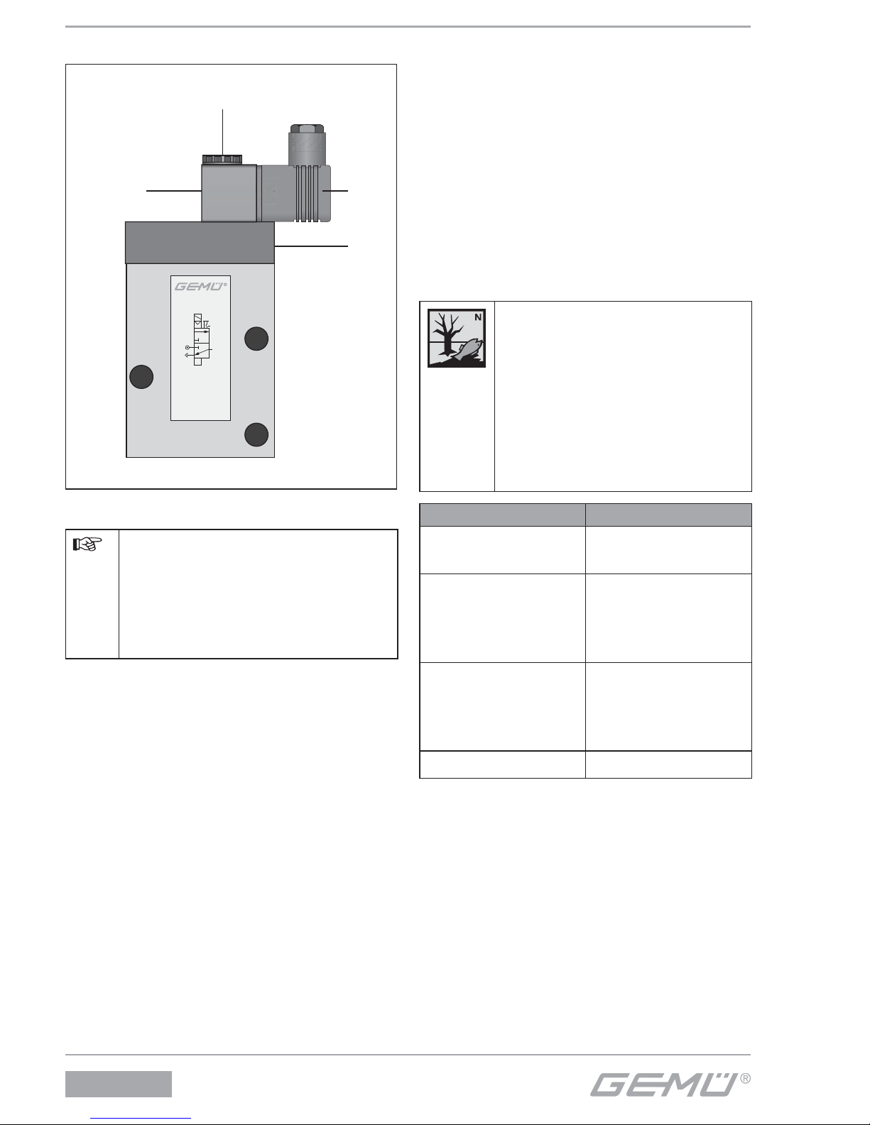
Typ 8357
2
10
12
1
3
7
2
8
10
Austausch Magnetspule
Das Vorsteuer-Magnetventil kann
während des Magnetwechsels
nicht elektrisch, sondern
lediglich manuell über die
Handnotbetätigung 8 bedient
werden.
1. Gerätesteckdose 2 spannungsfrei
schalten.
2. Befestigungsmutter 7 lösen.
3. Gerätesteckdose 2 von Magnetspule 10
abziehen.
4. Neue Magnetspule 10 auf Magnethülse
setzen.
5. Gerätesteckdose 2 wieder auf
Magnetspule 3 aufsetzen.
6. Befestigungsmutter 7 handfest anziehen.
7. Gerätesteckdose 2 und Flachdichtung
auf Magnetspule 10 stecken und mit
Befestigungsschraube festziehen
(60 Ncm).
13 Demontage
Demontage erfolgt unter den gleichen
Vorsichtsmaßnahmen wie die Montage.
G Vorsteuer-Magnetventil demontieren
(siehe Kapitel 10.1 „Montage“).
G Pneumatische Leitung(en) trennen (siehe
Kapitel 10.2 „Pneumatischer Anschluss“).
G Elektrische Leitung(en) trennen (siehe
Kapitel 10.3 „Elektrischer Anschluss“).
14 Entsorgung
G Alle Ventilteile
entsprechend den
Entsorgungsvorschriften /
Umweltschutzbestimmungen
entsorgen.
G Auf Restanhaftungen
und Ausgasung von
eindiff undierten Medien
achten.
Teile Entsorgung
Ventilgehäuse,
Ventildeckel
gemäß Werkstoff -
kennzeichnung
Schrauben,
Magnetanker,
Magnethülse,
Druckfedern
als
Metallkernschrott
O-Ringe,
Membranen,
Dichtungs- und
Kunststoff teile
Als
hausmüllähnlicher
Gewerbemüll
Magnetspule Als Elektroschrott
Page 13
8357
13 / 32
15 Rücksendung
G Vorsteuer-Magnetventil reinigen.
G Rücksendeerklärung bei GEMÜ
anfordern.
G Rücksendung nur mit vollständig
ausgefüllter Rücksendeerklärung.
Ansonsten erfolgt keine
Gutschrift bzw. keine
Erledigung der Reparatur
sondern eine kostenpflichtige Entsorgung.
Hinweis zur Rücksendung:
Aufgrund gesetzlicher
Bestimmungen zum Schutz
der Umwelt und des Personals
ist es erforderlich, dass die
Rücksendeerklärung vollständig
ausgefüllt und unterschrieben den
Versandpapieren beiliegt. Nur
wenn diese Erklärung vollständig
ausgefüllt ist, wird die Rücksendung
bearbeitet!
16 Hinweise
Hinweis zur Richtlinie 2014/34/EU
(ATEX Richtlinie):
Ein Beiblatt zur Richtlinie 2014/34/
EU liegt dem Produkt bei, sofern es
gemäß ATEX bestellt wurde.
Hinweis zur Mitarbeiterschulung:
Zur Mitarbeiterschulung nehmen
Sie bitte über die Adresse auf der
letzten Seite Kontakt auf.
Im Zweifelsfall oder bei Missverständnissen
ist die deutsche Version des Dokuments
ausschlaggebend!
17 Fehlersuche / Störungsbehebung
Fehler Mögliche Ursache Störungsbehebung
Keine Funktion
Stromversorgung nicht
in Ordnung
Stromversorgung und Anschluss gemäß
Typenschild sicherstellen
Magnetspule defekt Durchgang prüfen, ggf. Magnetspule
austauschen
Betriebsdruck zu hoch Betriebsdruck prüfen, ggf. Betriebsdruck
reduzieren
Steuerbohrung
verschmutzt
Vorsteuer-Magnetventil reinigen, ggf.
Schmutzfänger vorschalten
Magnetanker blockiert Magnetanker und Magnethülse reinigen
Handnotbetätigung auf
Position 1
Handnotbetätigung gemäß Kapitel 10.4
lösen
VorsteuerMagnetventil undicht
Hauptventilsitz undicht Hauptventilsitz reinigen
Page 14
8357
14 / 32
18 Herstellererklärung
Herstellererklärung
Gemäß Anhang VII der Richtlinie 2014/68/EU
Wir, die Firma GEMÜ Gebr. Müller Apparatebau GmbH & Co. KG
Fritz-Müller-Straße 6-8
D-74653 Ingelfingen
erklären, dass unten aufgeführte Armaturen gemäß Artikel 4, Absatz 3 der Druckgeräterichtlinie
2014/68/EU in Übereinstimmung mit der guten Ingenieurpraxis ausgelegt und hergestellt sind.
Beschreibung
Magnetventil / Druckhaltendes Ausrüstungsteil
Max. zulässiger Betriebsdruck: 10 bar
Nennweite: DN 2
Benennung der Armaturen - Typenbezeichnung:
Magnetventil GEMÜ 8357
Einstufung der Amaturen:
Nach Artikel 4, Absatz 3 gute Ingenieurpraxis
DN ≤ 25
Zusätzliche Angaben:
Die Produkte werden entwickelt und produziert nach GEMÜ eigenen Verfahrensanweisungen und
Qualitätsstandards, welche die Forderungen der ISO 9001 und der ISO 14001 erfüllen.
Die Produkte dürfen gemäß Artikel 4, Absatz 3 der Druckgeräterichtlinie 2014/68/EU keine CEKennzeichnung tragen.
Joachim Brien
Leiter Bereich Technik
Ingelfingen-Criesbach, September 2016
Page 15
8357
15 / 32
19 Konformitätserklärung
Konformitätserklärung
Wir, die Firma GEMÜ Gebr. Müller Apparatebau GmbH & Co. KG
Fritz-Müller-Straße 6-8
D-74653 Ingelfi ngen
erklären, dass das unten aufgeführte Produkt den folgenden Richtlinien entspricht:
• Niederspannungsrichtlinie 2006/95/EG
• EMV-Richtlinie 2004/108/EG
Produkt: GEMÜ 8357
Joachim Brien
Leiter Bereich Technik
Ingelfingen-Criesbach, August 2015
Page 16
1 General information
Prerequisites for the correct function of the
GEMÜ pilot solenoid valve:
Correct transport and storage
Installation and commissioning by trained
personnel
Operation according to these installation,
operating and maintenance instructions
Recommended maintenance
Correct installation, operation and servicing
or repair work ensure faultless pilot solenoid
valve operation.
The descriptions and instructions
apply to the standard versions.
For special versions not described
in these installation, operating
and maintenance instructions the
basic information contained herein
applies in combination with any
additional special documentation.
All rights including copyright
and industrial property rights are
expressly reserved.
2 General safety information
The safety information in these installation,
operating and maintenance instructions
refers only to the individual pilot solenoid
valve itself. Potentially dangerous conditions
can arise in combination with other plant
components, which need to be considered
on the basis of a risk analysis.
The operator is responsible for the
production of the risk analysis and for
compliance with the resulting precautionary
measures and regional safety regulations.
Contents
1 General information 16
2 General safety information 16
2.1 Information for service and
operating personnel 17
2.2 Warning notes 17
2.3 Symbols used 18
3 Intended area of use 18
4 Scope of delivery 18
5 Technical data 19
6 Order data 19
7 Transport and storage 20
7.1 Transport 20
7.2 Storage 20
8 Functional description 20
9 Construction 20
10 Installation and operation 21
10.1 Installation 21
10.2 Pneumatic connection 22
10.3 Electrical connection 23
10.4 Manual override 24
11 Commissioning 25
12 Inspection and servicing 25
12.1 Solenoid coil replacement 26
13 Disassembly 26
14 Disposal 26
15 Returns 27
16 Information 27
17 Troubleshooting /
Fault clearance 27
18 Manufacturer’s declaration 28
19 Declaration of Conformity 29
8357
16 / 32
Page 17
The safety information does not take into
account:
Unexpected incidents and events, which
may occur during installation, operation
and servicing.
Local safety regulations which must be
adhered to by the operator and by any
additional installation personnel.
2.1 Information for service and
operating personnel
The installation, operating and maintenance
instructions contain fundamental safety
information that must be observed during
commissioning, operation and servicing.
Non-compliance with these instructions may
cause:
Personal hazard due to electrical,
mechanical and chemical eff ects.
Hazard to nearby equipment.
Failure of important functions.
Hazard to the environment due to the
leakage of dangerous materials.
Prior to commissioning:
G Read the installation, operating and
maintenance instructions.
G Provide adequate training for the
installation and operating personnel.
G Ensure that the contents of the
installation, operating and maintenance
instructions have been fully understood
by the responsible personnel.
G Defi ne the areas of responsibility.
G Determine servicing and inspection
intervals.
During operation:
G Keep the installation, operating and
maintenance instructions available at the
place of use.
G Observe the safety information.
G Use the pilot solenoid valve only in
accordance with the operational data.
G Any servicing work and repairs not
described in the installation, operating
and maintenance instructions may not be
performed without previous consultation
with GEMÜ.
G Strictly observe the safety data sheets or
the safety regulations valid for the media
used.
In case of uncertainty
Consult the nearest GEMÜ sales offi ce.
2.2 Warning notes
Wherever possible, warning notes are
organised according to the following
scheme: Warning notes are always marked
with a signal word and sometimes also with
a symbol for the specifi c danger.
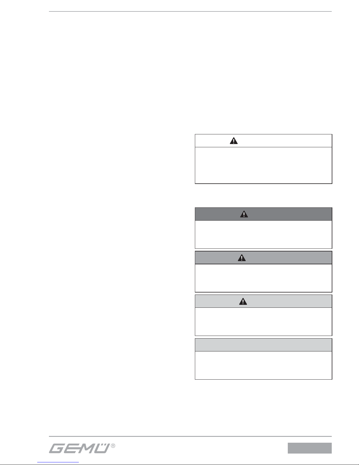
SIGNAL WORD
Type and source of the danger
® Possible consequences of non-
observance.
G Measures for avoiding danger.
The following signal words and danger
levels are used:
DANGER
Imminent danger!
® Non-observance will lead to death or
severe injury.
WARNING
Potentially dangerous situation!
® Non-observance can cause death or
severe injury.
CAUTION
Potentially dangerous situation!
® Non-observance can cause moderate
to light injury.
CAUTION (WITHOUT SYMBOL)
Potentially dangerous situation!
® Non-observance can cause damage to
property.
8357
17 / 32
Page 18
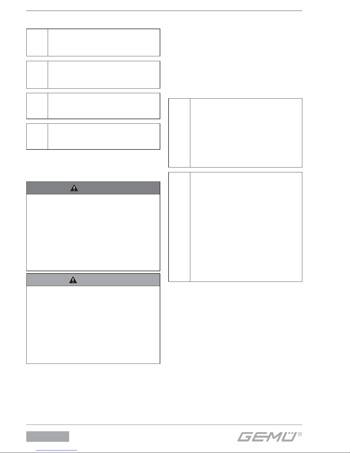
2.3 Symbols used
Hand:
indicates general information and
recommendations.
G
Bullet point:
indicates the tasks to be
performed.
®
Arrow:
indicates the response(s) to tasks.
Enumeration sign
3 Intended area of use
DANGER
Danger of explosion!
® Risk of severe injury or death!
G Use of the pilot solenoid valve in
potentially explosive areas is not
permissible.
G ATEX version: The pilot solenoid
valve may only be used in potentially
explosive zones confi rmed in the
declaration of conformity (ATEX).
WARNING
Use the pilot solenoid valve only for
the intended purpose!
® Otherwise the manufacturer liability and
guarantee will be void.
G Use the pilot solenoid valves only
in accordance with the operating
conditions specifi ed in the contract
documentation and in the installation,
operating and maintenance instructions
The GEMÜ 8357 pilot solenoid valve is
designed for the control of double acting
pneumatic cylinders and membrane
actuators or other pneumatic actuators.
The pilot solenoid valve may only be
used providing the product technical
criteria are complied with (see chapter 5
“Technical data”).
Do not paint the bolts and plastic parts of
the pilot solenoid valve!
Ensure compliance with the limiting
values of the harmonised standards
EN 6100-6-3 and EN 6100-6-1
and thus meeting the requirements
of the directive 2004/108/EC
(Electromagnetic compatibility) by
suitable electrical wiring of the pilot
solenoid valves.
The pilot solenoid valve is in
accordance with Article 4,
Paragraph 3 of the Pressure
Equipment Directive (PED)
2014/68/EU. This means that they
are designed and manufactured
according to sound engineering
practice applicable in the member
state. The CE-marking on the pilot
solenoid valve does not refer to
the PED. Thus a declaration of
conformity in accordance with this
directive is not necessary.
4 Scope of delivery
The pilot solenoid valve is supplied as a
separately packed component. The female
threads are sealed with caps.
The following is included in the scope of
delivery:
Pilot solenoid valve with solenoid coil
Plug
8357
18 / 32
Page 19
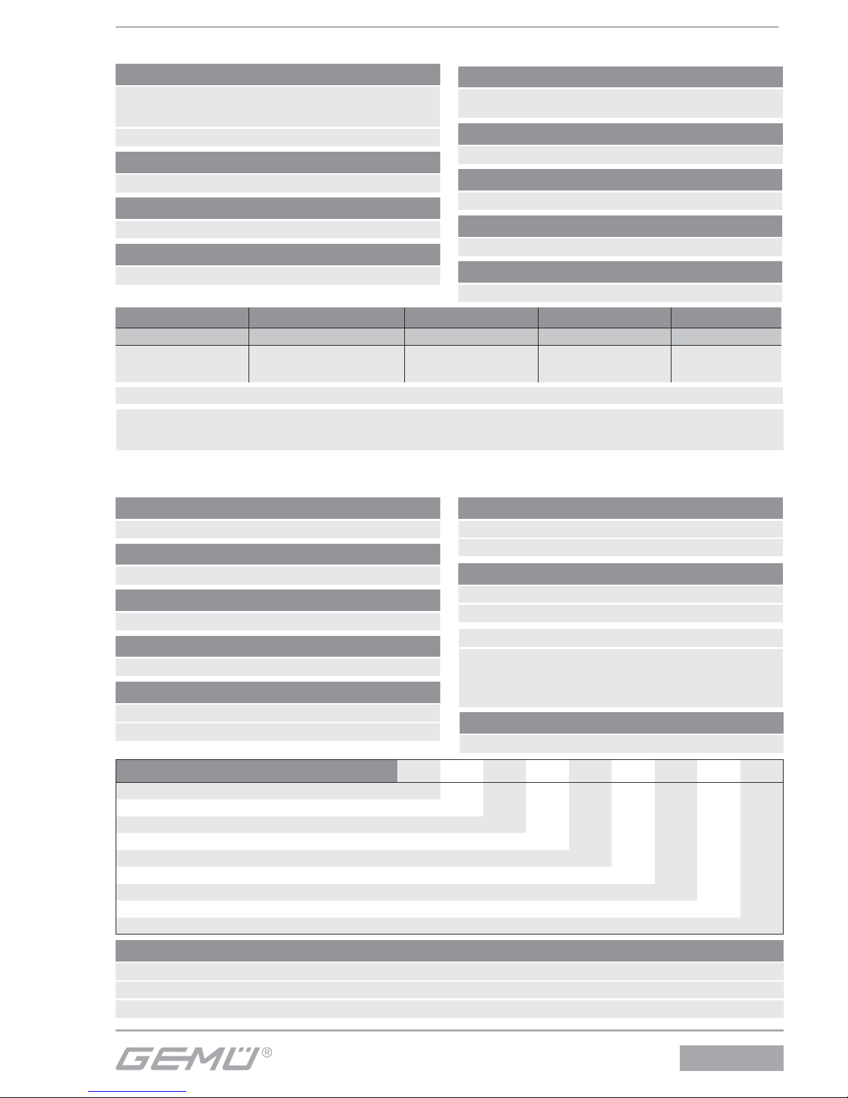
5 Technical data
Wiring note:
Special wiring on request. When using electronic switches and additional wiring, carefully design out any potential residual currents upon installation.
Nominal size Operating pressure Flow rate value Remark Weight
[DN] [bar]
[l/min]
[kg]
6 1,0 - 10
1200*
Back flow through R
cannot be throttled
0,4
* 6 bar pressure 1 bar ∆p
Working medium
Filtered, lubricated or unlubricated compressed air which has
no negative impact on the physical and chemical properties
of the body and seal material.
Perm. temp. of working medium -10...+60 °C
Switching time
Approx. 20 ms
Protection class
IP 65 (Ex design on request)
Power consumption
AC operation 4.9 VA
DC operation 2.7 W
Duty cycle
Continuous duty
Alternative versions
Version according to ATEX
Permissible voltage tolerance
±10 to VDE 0580
Installation position
Optional
Flow direction
Stipulated
6 Order data
Order example
8357 6 M 1 14 2 1 230 50
Type 8357
Nominal size 6
Body configuration (code) M
Connection (code) 1
Valve body material (code) 14
Seal material (code) 2
Control function 1
Supply voltage (code) 230
Mains frequency (code) 50
Available voltages/Frequency
AC 24 V AC 50 Hz
230 V AC 50 Hz
DC 24V DC -
Other voltages on request
Supply voltage Code
24 V 24
230 V 230
Mains frequency Code
50 Hz 50
DC DC
Body confi guration Code
Multi-port M
Connection Code
Threaded sockets DIN ISO 228 1
Valve body material Code
Aluminium 14
Seal material Code
Perbunan (NBR) 2
Switch position Code
Closed neutral position 1
Open neutral position 2
Ordering note
Suitable plug complying with DIN EN 175301-803 form A, loose plug: type GEMÜ 1220/1221
Direct mounting to valve with G 1/4“ thread with double threaded nipple type GEMÜ 1755
Without plug K-no. 1007, in Ex design K-no. 6491
Special function Code
ATEX X
8357
19 / 32
Page 20
7 Transport and storage
7.1 Transport
G Only transport the pilot solenoid valve
by suitable means. Do not drop. Handle
carefully.
G Dispose of packing material according
to relevant local or national disposal
regulations / environmental protection
laws.
7.2 Storage
G Store the pilot solenoid valve free
from dust and moisture in its original
packaging.
G Store the pilot solenoid valve only with
the connections blocked off .
G Avoid UV rays and direct sunlight.
G When storing over a longer period of
time do not exceed storage temperatures
from -10 °C to +20 °C. Raised storage
temperatures may lead to a reduced life
of sealing materials.
G Solvents, chemicals, acids, fuels or
similar fl uids must not be stored in the
same room as valves and their spare
parts.
8 Functional description
The servo assisted 3/2-way pilot solenoid
valve is indirectly controlled. The body
is made of aluminium. The plastic
encapsulated coil is detachable. The T-ring
piston slide valve has a soft elastomer
seal. The pilot solenoid valve has a manual
override. The electrical connection is made
via a plug complying with DIN EN 175301803 form A.
Switch position:
2
10
12
1
3
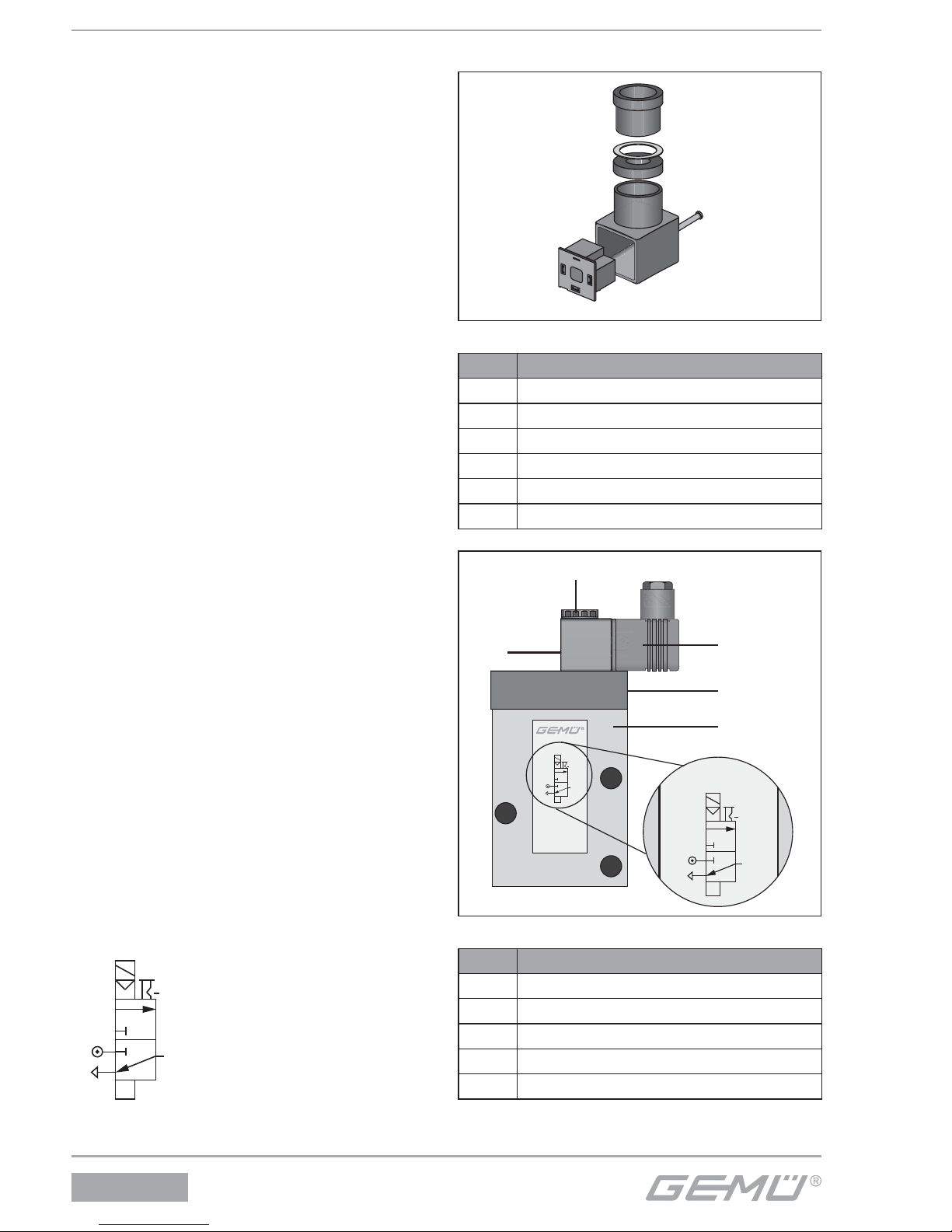
9 Construction
1
2
3
4
5
6
Plug
Item Name
1 Screw
2 Plug
3 Terminal block
4 Pressure ring
5 Gasket
6 Cable entry
Typ 8357
7
2
8
9
2
10
12
1
3
2
10
12
1
3
10
Construction
Item Name
2 Plug
7 Fastening nut
8 Manual override
9 Valve body
10 Solenoid coil
8357
20 / 32
Page 21
10 Installation and operation
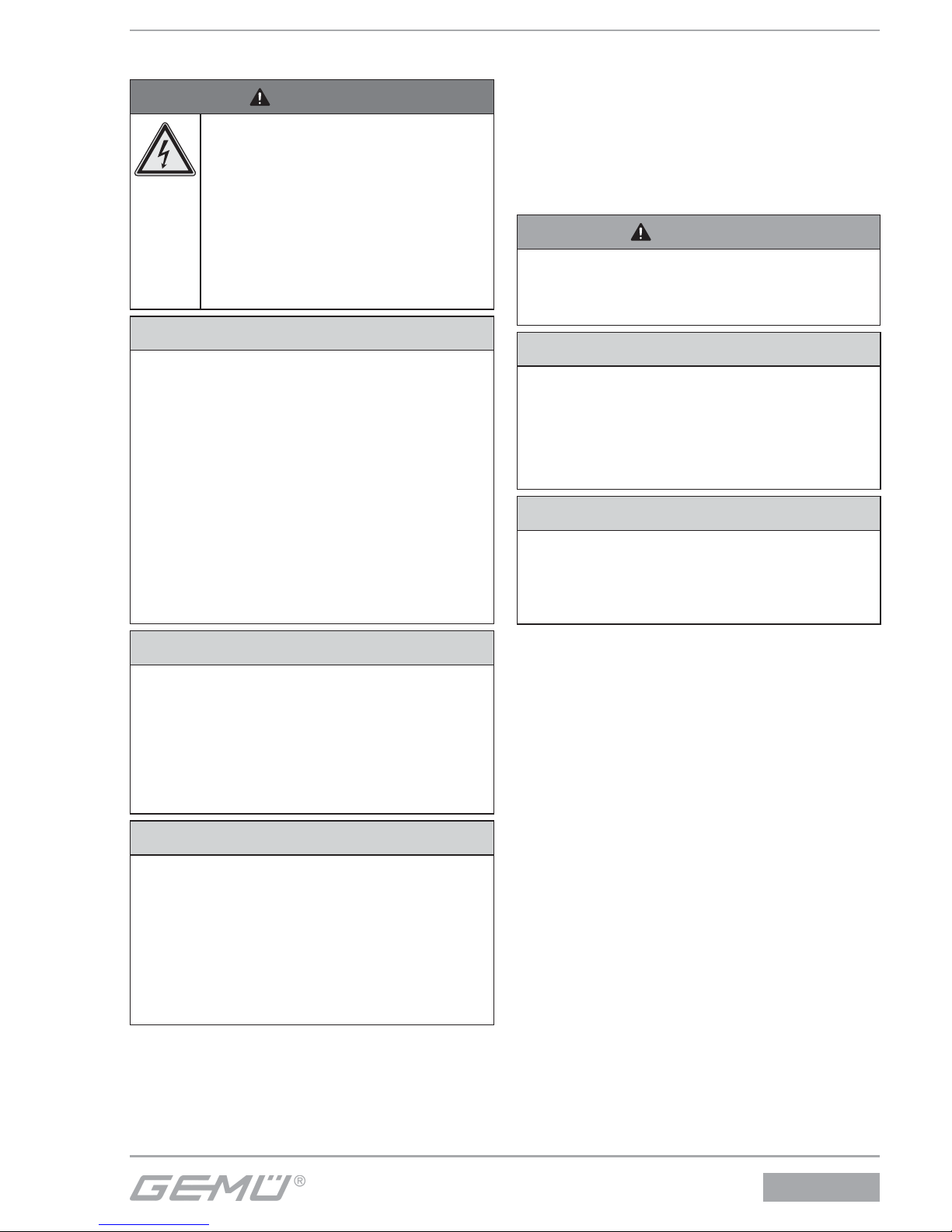
DANGER
Risk of electric shock!
® There is a danger of injury or
death (if operating voltage
is higher than safe extra low
voltage)!
G Before performing any work on
the pilot solenoid valve switch
off power and protect circuit
from being switched on again.
CAUTION
Functional impairment of the pilot
solenoid valve by contaminated media!
® The pilot solenoid valve will cease to
open or close if the control apertures
are blocked or if the armature is blocked
by dirt.
G The piping system should be cleaned
before installing the pilot solenoid valve.
G Fit a strainer having a mesh size of ≤
0.25 mm in front of the valve inlet if the
media are contaminated.
G Operate the pilot solenoid valve by
switching at least once a month.
CAUTION
Destruction of the pilot solenoid valve
by freezable medium!
® The pilot solenoid valve is not frost-
protected.
G Pilot solenoid valves using freezable
media should only be operated above
freezing point.
CAUTION
Danger from fl ow contrary to fl ow
direction!
® Damage to the pilot solenoid valve.
G Only operate the pilot solenoid valve in
fl ow direction.
G Take precautionary measures in case of
expected reverse fl ow (e.g. non-return
valve).
10.1 Installation
Prior to installation:
G Check the suitability of the
pilot solenoid valve prior to the
installation!
See chapter 5 “Technical data”.
WARNING
The equipment is subject to pressure!
® Risk of severe injury or death!
G Only work on depressurized plant.
CAUTION
Do not use the solenoid coil as a lever!
® Damage to the solenoid coil or bush!
G Use only the spanner fl ats provided to
screw the pilot solenoid valve to the
piping.
CAUTION
Stresses in the valve body!
® Damage to the valve body
G Only install the pilot solenoid valve in
aligned pipes.
G Installation work must only be performed
by trained personnel.
G Use appropriate protective gear as
specifi ed in plant operator’s guidelines.
8357
21 / 32
Page 22
Installation location:
CAUTION
G Do not apply external force to the pilot
solenoid valve.
Battery mounting with central air
supply possible.
Installation position:optional.
Manual override and electrical plug must
be accessible.
Installation:
1. Ensure the suitability of the valve for
each respective use. The valve must
be appropriate for the piping system
operating conditions (medium, medium
concentration, temperature and
pressure) and the prevailing ambient
conditions. Check the technical data of
the valve and the materials.
2. Shut off plant or plant component.
3. Secure against recommissioning.
4. Depressurize the plant or plant
component.
5. Completely drain the plant (or plant
component) and let it cool down until
the temperature is below the media
vaporization temperature and scalding
can be ruled out.
6. If necessary, correctly decontaminate,
rinse and ventilate the plant or plant
component.
7. If necessary, fi t a strainer in front of the
valve inlet.
8. Carefully remove the caps from the
female threads of the.pilot solenoid
valve.
9. Screw the pilot solenoid valve to the
appropriate device with two screws.
10. Connect the control medium lines (see
chapter 10.2 “Pneumatic connection”).
11. Connect the cable (see chapter 10.3
“Electrical connection”).
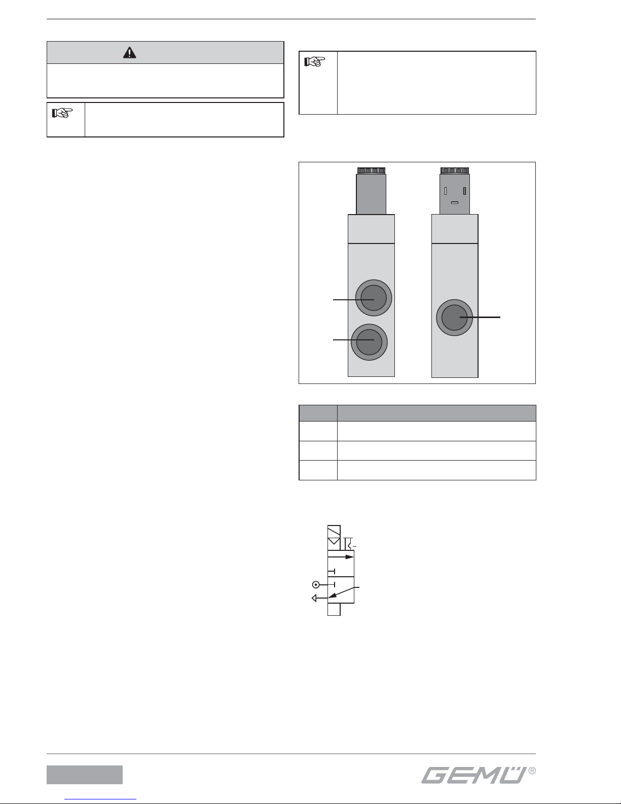
10.2 Pneumatic connection
Connect the control medium lines
tension-free and without any bends
or knots! Use suitable connectors
depending on the application.
Thread size of the control medium
connectors: G1/4
1
3
2
Connectors
Item Name
1 Air supply
2 Outlet
3 Exhaust air
Switch position:
2
10
12
1
3
8357
22 / 32
Page 23
10.3 Electrical connection
DANGER
Risk of electric shock!
® There is a danger of injury or
death (if operating voltage
is higher than safe extra low
voltage)!
G Electrical connection only to
be carried out by an electrical
expert.
G Disconnect the cable from the
power supply before making
the electrical connection.
Every valve solenoid must have
a fuse appropriate for its rated
current (max. 3 times rated current
in accordance with DIN 41571
or IEC 60127-2-1) or a motor
protection switch with short circuit
and thermal instantaneous trip
(setting to rated current) connected
upstream as protection against
short circuits. This fuse may be
located in the corresponding power
supply unit or must be connected
separately upstream. The fuse
rated voltage must be equal to or
greater than the specifi ed nominal
voltage of the solenoid. The
breaking capacity of the fuse unit
must be equal to or greater than
the maximum short circuit current
occurring at the site of installation
(usually 1500A).
1
2
3
4
5
6
Typ 8357
2
10
12
1
3
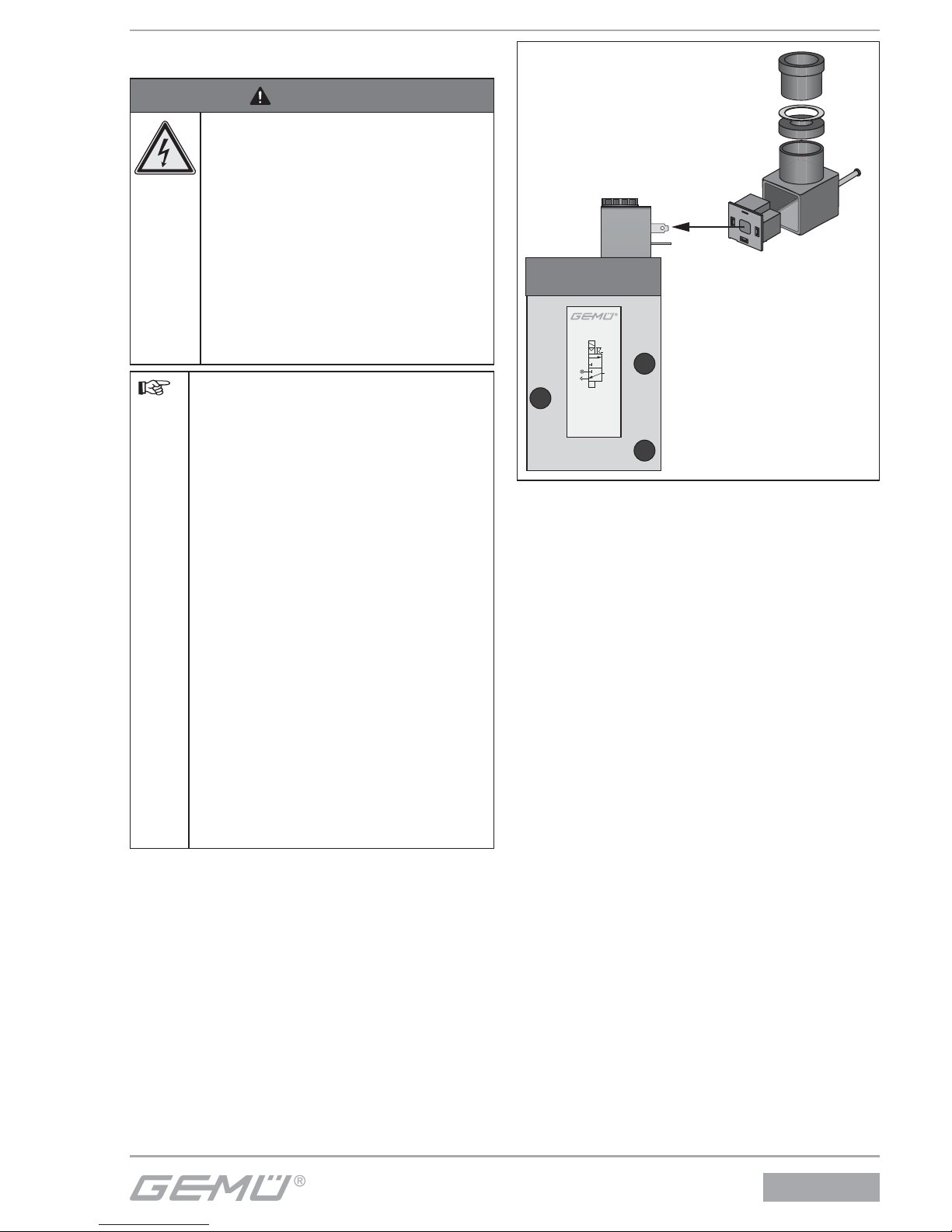
Electrical connection
1. Disconnect the plant from power supply.
2. Unscrew retaining screw 1.
3. Pull off plug 2 with terminal block 3 from
solenoid.
4. Press terminal block 3 carefully out of
plug 2.
5. Unscrew cable entry 6.
6. Remove pressure ring 4 and gasket 5.
7. Insert cable through cable entry 6,
pressure ring 4, gasket 5 and plug 2.
8357
23 / 32
Page 24
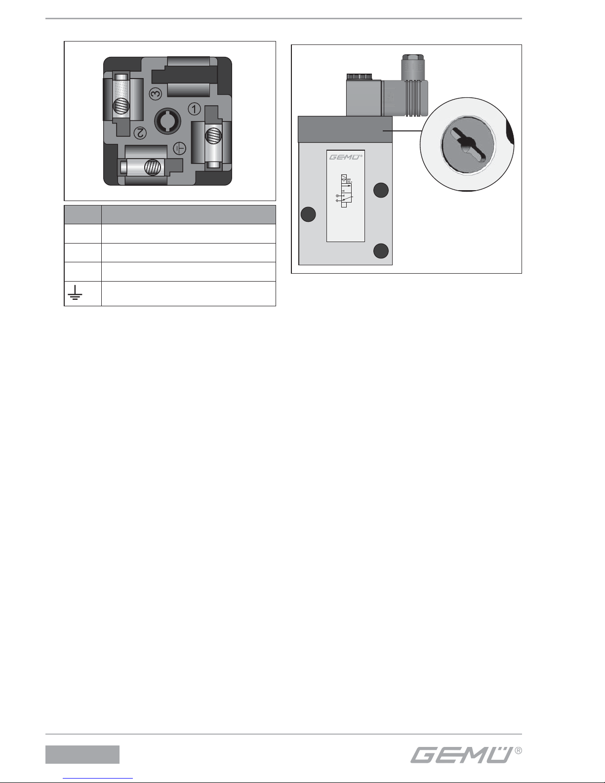
8. Connect the cable.
Item Name
1 Supply voltage
2 Supply voltage
3 Not connected
Earth
9. Push gasket 5 and pressure ring 4 into
plug 2.
10. Insert terminal block 3 again in the plug 2
until it audibly clicks in position.
11. Screw plug 2 to solenoid with retaining
screw 1 (max. 0,3 Nm).
12. Tighten cable entry 6.
10.4 Manual override
Typ 8357
2
10
12
1
3
1
0
8
Manual override
The pilot solenoid valves are equipped with
a manual override 8.
Only actuate the manual override in case
of malfunction!
Actuate valve via manual override:
G Turn the rotary screw with a screw driver
to position 1 (until it stops).
Close valve by manual override:
G Turn the rotary screw with a screw driver
to position 0 (until it stops).
8357
24 / 32
Page 25
11 Commissioning
CAUTION
Protect against leakage!
G Check the tightness of the media
connections prior to commissioning!
G Provide precautionary measures
against exceeding the maximum
permitted pressures caused by pressure
surges.
Prior to cleaning or commissioning the
plant:
G Check the tightness and the function of
the pilot solenoid valve.
G If the plant is new and after repairs blow
out the piping system with a fully opened
pilot solenoid valve (to remove any
harmful foreign matter).
Cleaning
The plant operator is responsible for
selecting the cleaning material and
performing the procedure.
12 Inspection and servicing
WARNING
Danger of burning from hot surfaces!
® In operation the solenoid coil can heat
up to 120 °C.
G Allow the solenoid coil and pipes to
cool down before servicing work.
WARNING
The equipment is subject to pressure!
® Risk of severe injury or death!
G Only work on depressurized plant.
CAUTION
G Servicing and maintenance work must
only be performed by trained personnel.
G GEMÜ shall assume no liability
whatsoever for damages caused
by improper handling or third-party
actions.
G In case of doubt, contact GEMÜ before
commissioning.
1. Use appropriate protective gear as
specifi ed in plant operator’s guidelines.
2. Shut off plant or plant component.
3. Secure against recommissioning.
4. Depressurize the plant or plant
component.
G Only use genuine GEMÜ spare
parts!
G When ordering spare part, please
state the complete order number
of the pilot solenoid valve.
The operator must carry out regular visual
examination of the valves dependent on
the operating conditions and the potential
danger in order to prevent leakage and
damage. The valve also has to be checked
for wear in the corresponding intervals.
8357
25 / 32
Page 26
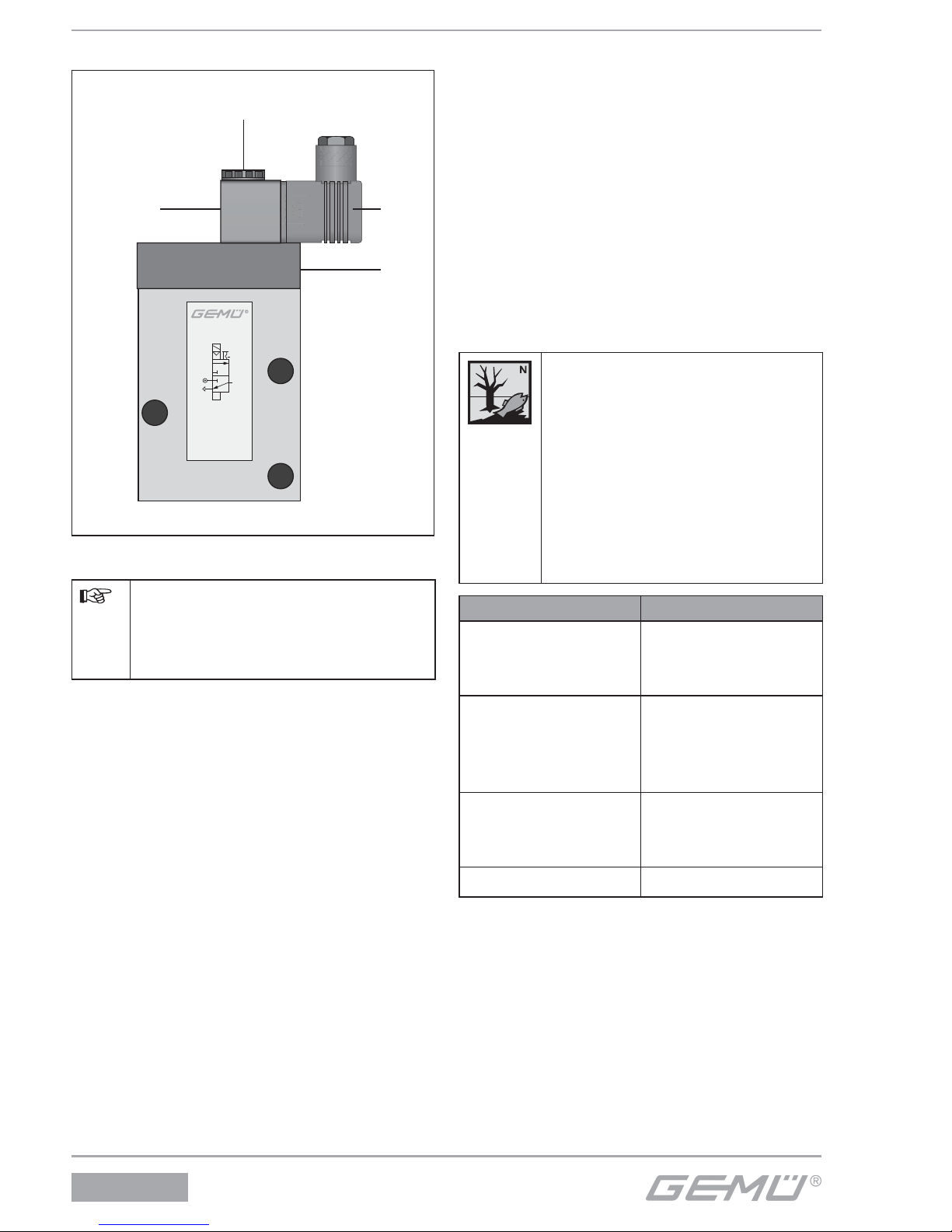
12.1 Solenoid coil replacement
Typ 8357
2
10
12
1
3
7
2
8
10
Solenoid coil replacement
When replacing the solenoid coil
the pilot solenoid valve cannot
be operated electrically but only
manually via the manual override 8.
1. Disconnect the plug 2 from power
supply.
2. Undo the fastening nut 7.
3. Pull the plug 2 off the solenoid coil 10.
4. Place a new solenoid coil 10 on the
bush.
5. Place the plug 2 onto the solenoid coil 3.
6. Tighten the fastening nut 7 manually.
7. Push the plug 2 and gasket onto the
solenoid coil 10 and tighten with the
fi xing screw (60 Ncm).
13 Disassembly
Disassembly is performed observing
the same precautionary measures as for
installation.
G Disassemble the pilot solenoid valve (see
chapter 10.1 “Installation”).
G Disconnect the pneumatic line(s) (see
chapter 10.2 “Pneumatic connection”).
G Disconnect the electric wire(s) (see
chapter 10.3 “Electrical connection”).
14 Disposal
G All valve parts must be
disposed of according to
relevant local or national
disposal regulations /
environmental protection
laws.
G Pay attention to adhered
residual material and gas
diff usion from penetrated
media.
Parts Disposal
Valve bodies, valve
covers
in accordance with
material identifi ca-
tion
Screws,
armatures, bushes,
compression
springs
as metallic core
scrap
O-rings,
diaphragms, sealing
and plastic parts
as domestic waste
type commercial
waste
Solenoid coil as electrical scrap
8357
26 / 32
Page 27
15 Returns
G Clean the pilot solenoid valve.
G Request a return delivery note from
GEMÜ.
G Returns must be made with a completed
return delivery note.
If not completed, GEMÜ cannot process
credits or
repair work
but will dispose of the goods at the
operator’s expense.
Note for returns:
Legal regulations for the protection
of the environment and personnel
require that the completed and
signed return delivery note
is included with the dispatch
documents. Returned goods can
be processed only when this note is
completed.
16 Information
Note on Directive 2014/34/EU
(ATEX Directive):
A supplement to Directive 2014/34/
EU is included with the product if it
was ordered according to ATEX.
Note on staff training:
Please contact us at the address
on the last page for staff training
information.
Should there be any doubts or
misunderstandings in the preceding text,
the German version of this document is the
authoritative document!
17 Troubleshooting / Fault clearance
Fault Possible cause Fault clearance
No function
Power supply not OK Check power supply and connection with
product label
Solenoid coil faulty Check continuity, replace solenoid coil if
necessary
Operating pressure too
high
Check operating pressure, reduce if
necessary
Control aperture
contaminated
Clean pilot solenoid valve, fi t strainer in
front if necessary
Armature blocked Clean the armature and the bush
Manual override in
position 1
Unlock the manual override as described
in chapter 10.4.
Pilot solenoid valve
leaking
Main valve seat
leaking
Clean main valve seat
8357
27 / 32
Page 28
18 Manufacturer’s declaration
Manufacturer’s declaration
According to annex VII of the Directive 2014/68/EU
Hereby we, GEMÜ Gebr. Müller Apparatebau GmbH & Co. KG
Fritz-Müller-Straße 6-8
D-74653 Ingelfingen
declare that the equipment listed below is designed and manufactured in compliance with the
sound engineering practice according to Article 4, Paragraph 3 of the Pressure Equipment Directive
2014/68/EU.
Description
Solenoid valve / Pressure accessory
Max. permissible operating pressure: 10 bar
Nominal size: DN 2
Description of the equipment - product type
Solenoid valve GEMÜ 8357
Classification of the valves:
Sound engineering practice according to Article 4, Paragraph 3
DN ≤ 25
Additional information:
The products are developed and produced according to GEMÜ process instructions and quality
standards which comply with the requirements of ISO 9001 and ISO 14001.
According to Article 4, Paragraph 3 of the Pressure Equipment Directive 2014/68/EU these products
must not be identified by a CE-label.
Joachim Brien
Head of Technical Department
Ingelfingen-Criesbach, September 2016
8357
28 / 32
Page 29
19 Declaration of Conformity
Declaration of Conformity
Hereby we, GEMÜ Gebr. Müller Apparatebau GmbH & Co. KG
Fritz-Müller-Straße 6-8
D-74653 Ingelfi ngen
declare that the product listed below complies with the following directives:
• Low Voltage Directive 2006/95/EC
• EMC Directive 2004/108/EC
Product: GEMÜ 8357
Joachim Brien
Head of Technical Department
Ingelfingen-Criesbach, August 2015
8357
29 / 32
Page 30

8357
30 / 32
Page 31

8357
31 / 32
Page 32

GEMÜ Gebr. Müller Apparatebau GmbH & Co. KG · Fritz-Müller-Str. 6-8 · D-74653 Ingelfi ngen-Criesbach
Telefon +49(0)7940/123-0 · Telefax +49(0)7940/123-192 · [email protected] · www.gemu-group.com
Änderungen vorbehalten · Subject to alteration · 03/2017 · 88464887
 Loading...