

Page 1
512, 514, 532
512, 514, 532
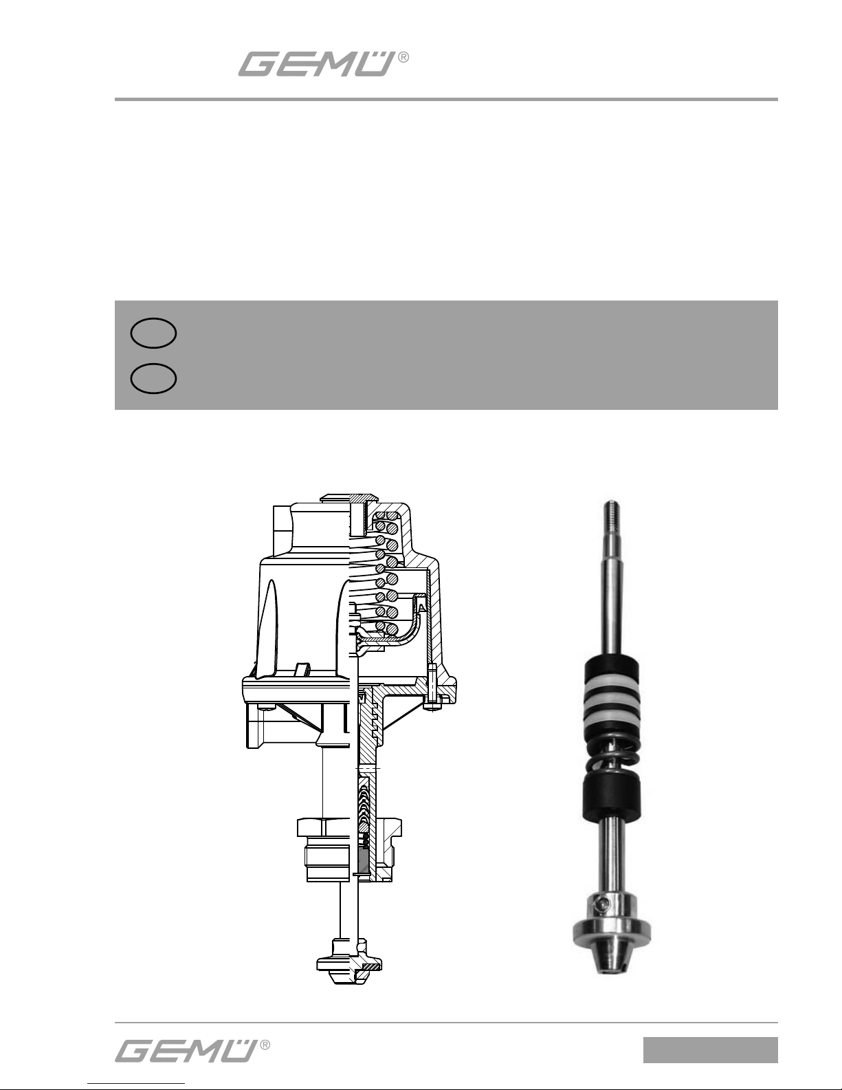
Austausch der Stopfbuchspackung
DE
ORIGINAL MONTAGEANLEITUNG
Replacement of the gland packing
GB
ASSEMBLY INSTRUCTIONS
Page 2
512, 514, 532
2 / 16
Allgemeine Hinweise
+
Einbau- und Montageanleitungen
GEMÜ 512, GEMÜ 514 und GEMÜ
532 beachten! Beschreibungen
und Instruktionen in dieser
Montageanleitung beziehen sich
auf Standardausführungen.
WARNUNG
Unter Druck stehende Armaturen!
® Gefahr von schwersten Verletzungen
oder Tod!
G Nur an druckloser Anlage arbeiten.
WARNUNG
Haube steht unter Federdruck!
® Gefahr von schwersten Verletzungen
oder Tod!
G Antrieb nur unter Presse öff nen.
WARNUNG
Aggressive Chemikalien!
® Verätzungen!
G Montage nur mit geeigneter
Schutzausrüstung.
VORSICHT
Heiße Anlagenteile!
® Verbrennungen!
G Nur an abgekühlter Anlage
arbeiten.
VORSICHT
Ventil nicht als Trittstufe oder
Aufstiegshilfe benutzen!
® Gefahr des Abrutschens / der
Beschädigung des Ventils.
VORSICHT
Maximal zulässigen Druck nicht
überschreiten!
® Eventuell auftretende Druckstöße
(Wasserschläge) durch
Schutzmaßnahmen vermeiden.
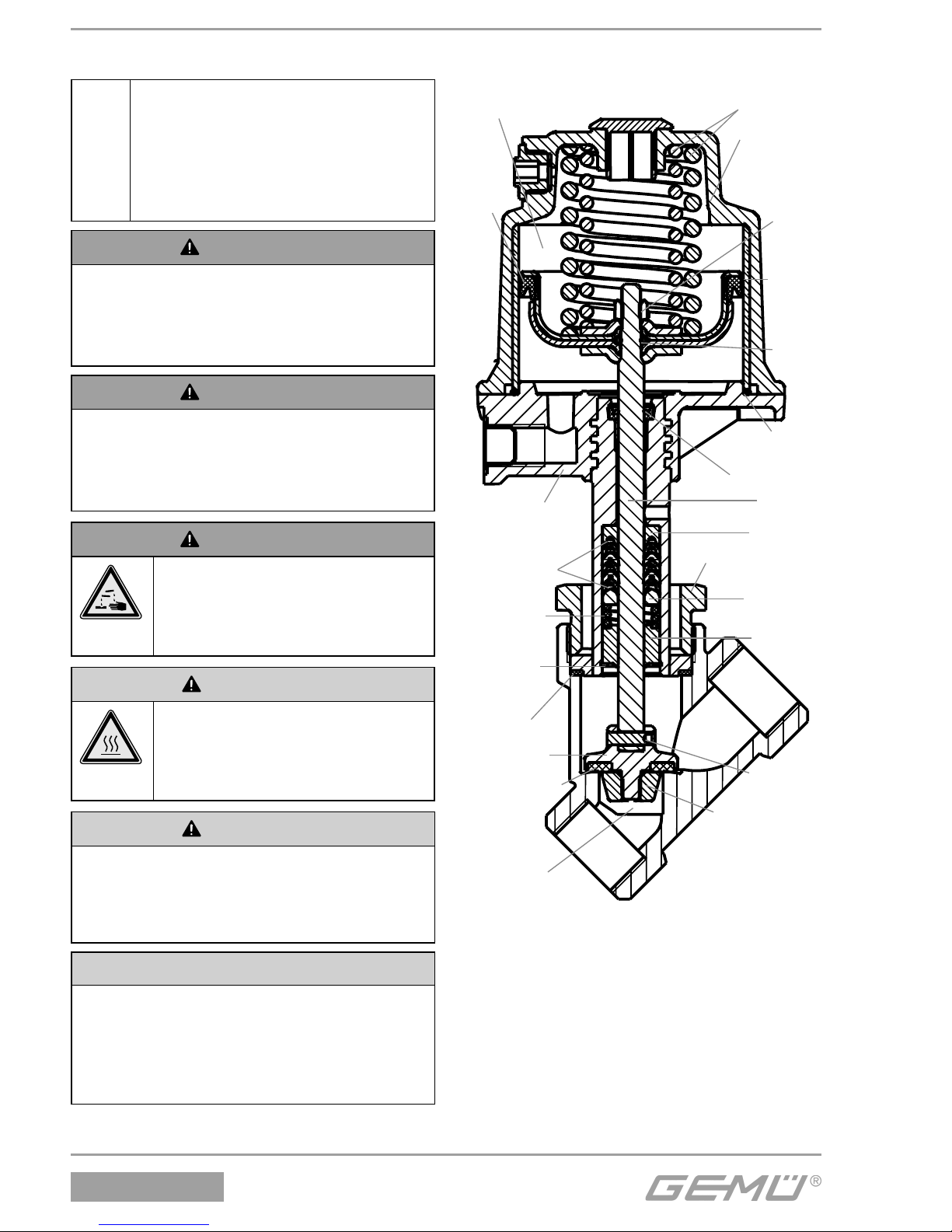
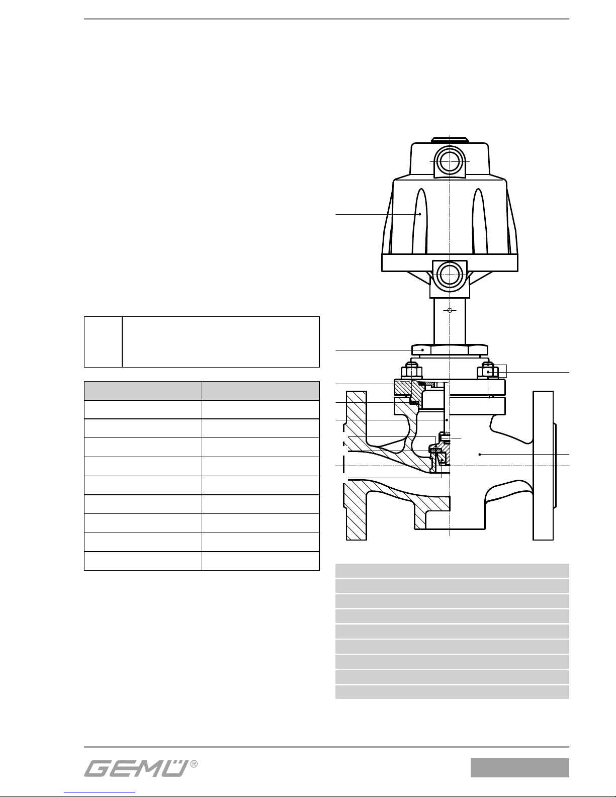
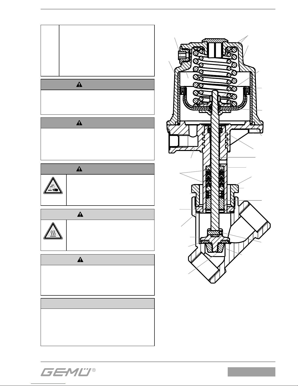
Ventilaufbau am Beispiel von
GEMÜ 514, 532
Druckfedern
Oberteil des
Antriebs
(Haube)
Kolben-
lauf-
buchse
13
O-Ring 24
Sechs-
kantmut-
ter 11
Unterteil des
Antriebs
Spindel 2
Führungs-
buchse 5
Sicherungsring 3
Druckfeder 6
Druckring 9
Stützring 7
V-Manschetten
8 und 33
O-Ring
22
Lippenring 21
Lippenring 26
Nietstift 16
Tellerscheibe 19
Ventilteller 15
Dichtring 4
Sitzdichtung 14
Antrieb A
Ventilkörper 1
Überwurfmutter a
Page 3
3 / 16
512, 514, 532
1 Montage / Demontage der
Stopfbuchspackung bei
GEMÜ 514, 532
Siehe auch Einbau- und Montageanleitungen GEMÜ 514 und GEMÜ 532
- Kapitel 11.1 "Montage des Ventils" und
Kapitel 20 "Schnittbilder und Ersatzteile".
1.1 Demontage Antrieb und
Dichtring 4
1. Antrieb A in Off en-Position bringen.
2. Überwurfmutter a lösen.
3. Antrieb A vom Ventilkörper 1
demontieren.
4. Dichtring 4 entnehmen.
+
Wichtig:
Nach Demontage alle Teile von
Verschmutzungen reinigen (Teile
dabei nicht beschädigen). Teile
auf Beschädigung prüfen, ggf.
auswechseln (nur Originalteile von
GEMÜ verwenden).
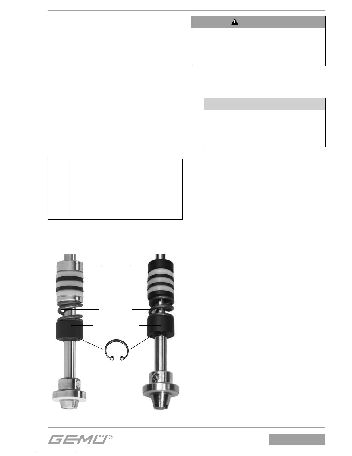
1.2 Auswechseln der
Stopfbuchspackung
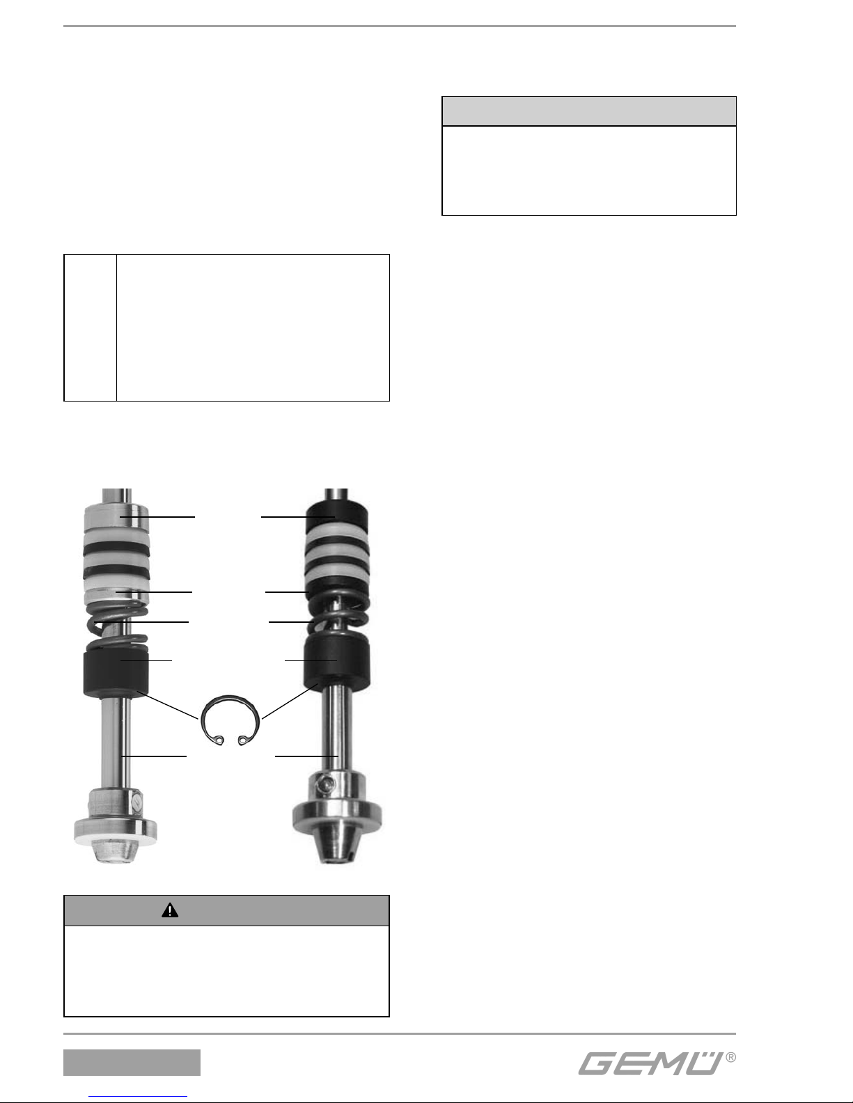
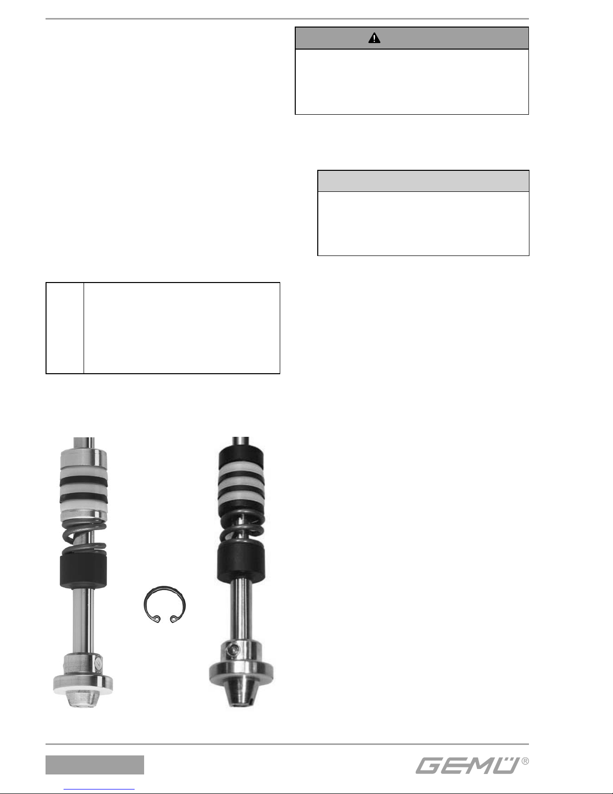
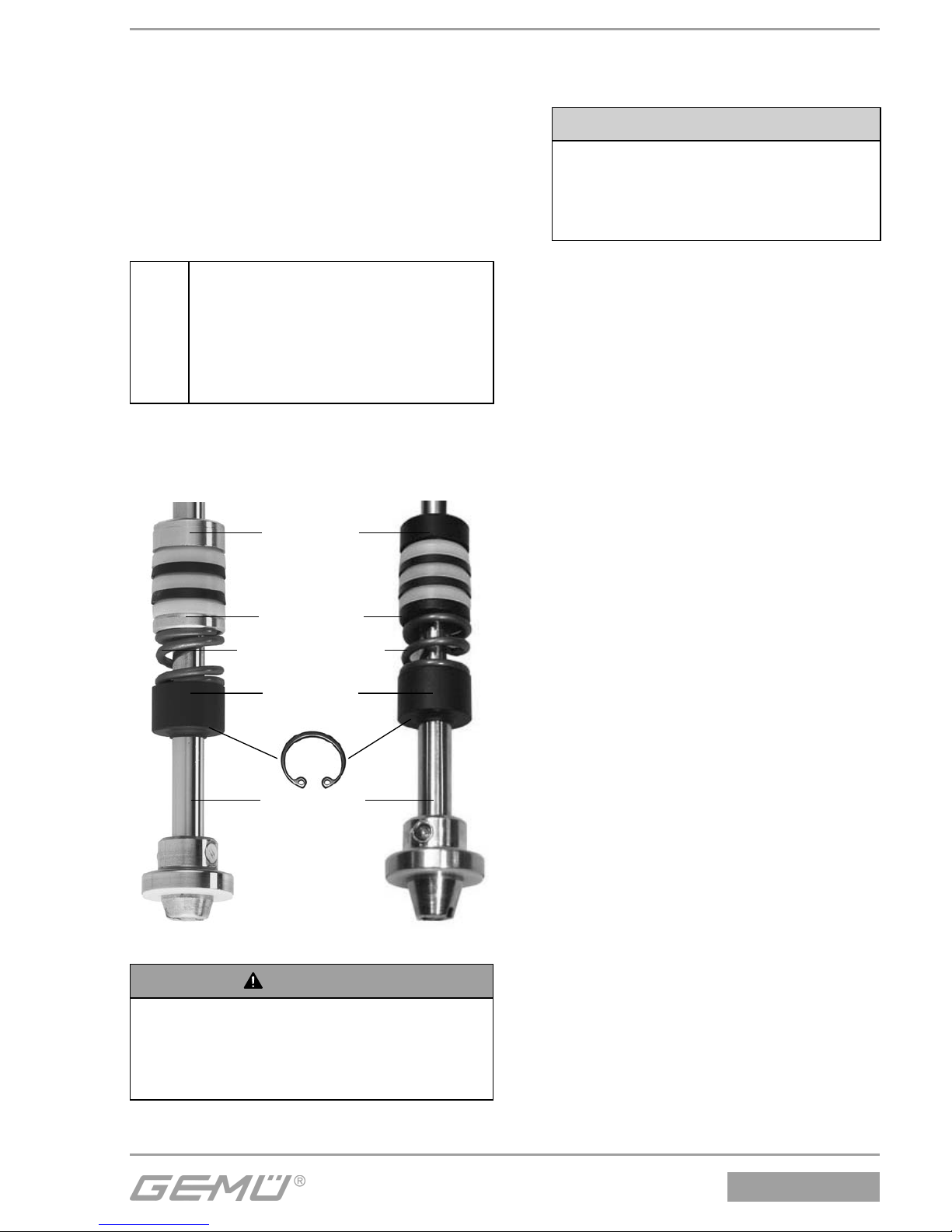
Messing-Ausführung Edelstahl-Ausführung
Stützring 7
V-Manschetten:
8 PTFE - hell
33 Elastomer - dunkel
Druckring 9
Druckfeder 6
Führungsbuchse 5
}
}
Ventilspindel 2
Sicherungsring 3
WARNUNG
Haube steht unter Federdruck!
® Gefahr von schwersten Verletzungen
oder Tod!
G Antrieb nur unter Presse öff nen.
1. Antrieb A demontieren wie in Kapitel
1.1, Punkte 1-4 beschrieben.
2. Antrieb A in Presse einspannen.
VORSICHT
Bruch der Haube bei zu starkem
Druck!
® Nur minimal nötigen Druck
ausüben.
3. Verbindungsschrauben zwischen
Oberteil und Unterteil des Antriebs A
lösen und entfernen.
4. Pressdruck langsam wegnehmen.
Antrieb A entlasten und öff nen.
5. Druckfedern und O-Ring 24 aus
Kolbenlaufbuchse 13 entnehmen.
6. Kolbenlaufbuchse 13 aus Oberteil des
Antriebs A ziehen und mit Dowcorning
111 Molycote einfetten.
7. Sechskantmutter 11 der Kolben-
Spindel-Verbindung im Unterteil des
Antriebs A lösen.
8. Lippenring 21 aus Kolbendeckel
entfernen.
9. O-Ring 22 zwischen Kolben und
Kolbendeckel entfernen.
10. Spindel 2 aus Unterteil des Antriebs A
nach unten heraus ziehen.
11. Lippenring 26 aus Unterteil des
Antriebs A entfernen.
12. Sicherungsring 3 im Unterteil des
Antriebs A mit geeignetem Werkzeug
(z. B. Seegerringzange) entfernen.
13. Nacheinander Führungsbuchse 5,
Druckfeder 6, Druckring 9,
V-Manschetten 8 und 33 und
Stützring 7 aus dem Rohr im Unterteil
des Antriebs A ziehen.
14. Neue Stopfbuchspackung in folgender
Reihenfolge in das Rohr im Unterteil
des Antriebs A einlegen:
1. Stützring 7
Page 4
512, 514, 532
4 / 16
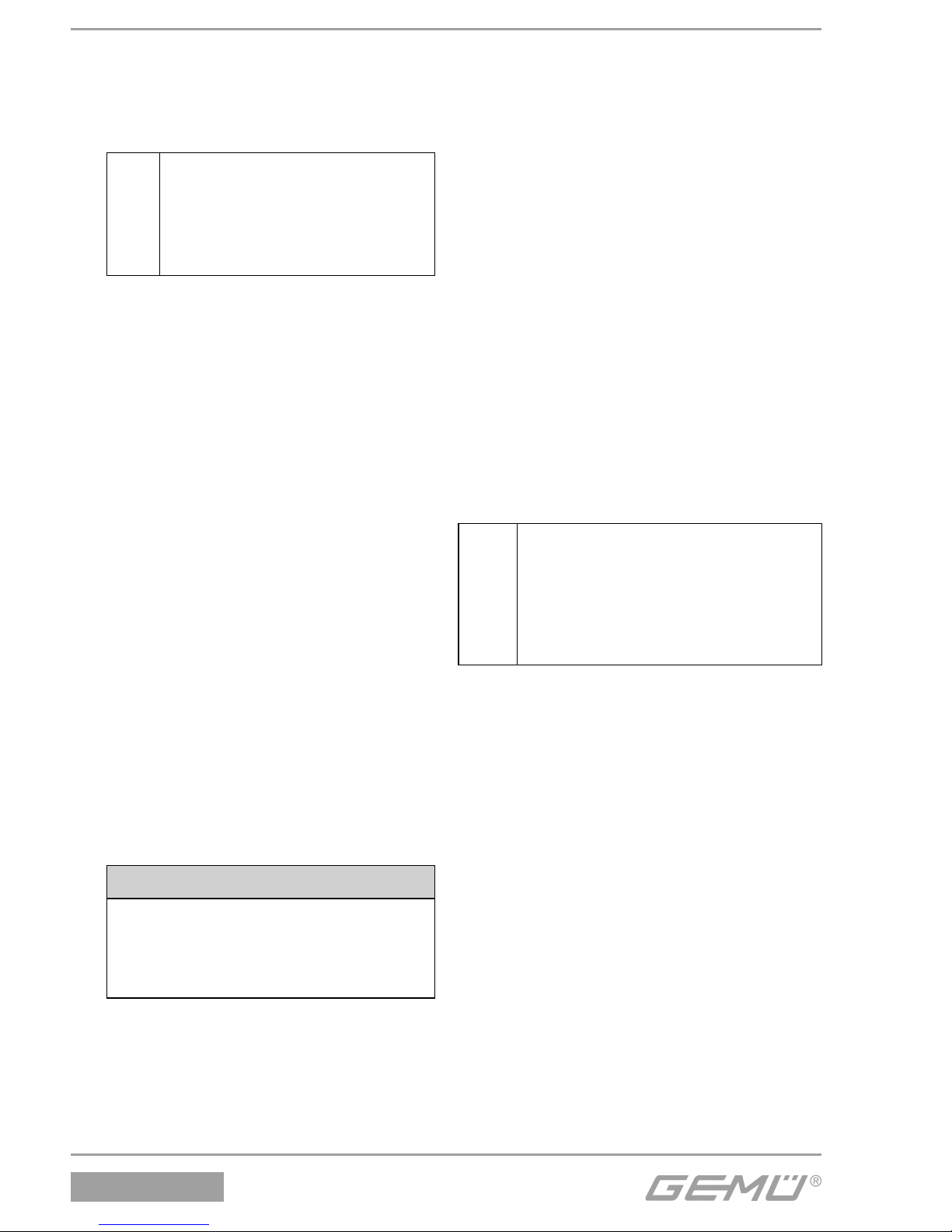
2. V-Manschetten 8 und 33 PTFE (nicht
vorhanden bei Antriebsgröße 2) /
Elastomer / PTFE / Elastomer / PTFE
(vorher fetten mit Dowcorning 111
Molycote)
+
V-Manschetten 8 und 33 mit
den scharfkantigen Seiten
in Richtung Ventilkörper
anordnen, sonst keine
Dichtfunktion!
3. Druckring 9
4. Druckfeder 6
5. Führungsbuchse 5
15. Stopfbuchspackung mit Sicherungsring
3 arretieren.
16. Neuen Lippenring 26 in Unterteil des
Antriebs A einlegen.
17. Spindel 2 durch Unterteil des Antriebs A
stecken.
18. O-Ring 22 zwischen Kolben und
Kolbendeckel einlegen.
19. Neuen Lippenring 21 in Kolbendeckel
einlegen.
20. Kolben-Spindel-Verbindung im Unterteil
des Antriebs A mit Sechskantmutter 11
fi xieren.
21. Kolbenlaufbuchse 13 in Oberteil des
Antriebs A drücken.
22. O-Ring 24 und Druckfedern in
Kolbenlaufbuchse 13 einlegen.
23. Oberteil und Unterteil des
Antriebs A auf einander stecken und
Verbindungsschrauben einlegen.
24. Antrieb A in Presse einspannen,
Oberteil und Unterteil des Antriebs A
bündig auf einander pressen.
VORSICHT
Bruch der Haube bei zu starkem
Druck!
® Nur minimal nötigen Druck
ausüben.
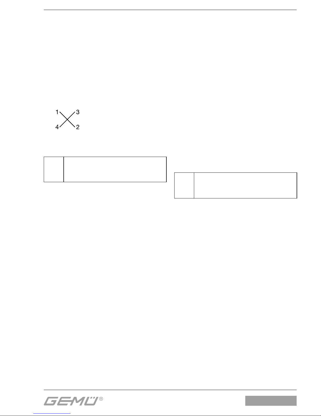
25. Verbindungsschrauben zwischen
Oberteil und Unterteil des Antriebs A
über Kreuz festziehen.
26. Pressdruck langsam wegnehmen.
27. Antrieb A montieren wie in Kapitel 1.4,
Punkte 1-5 beschrieben.
1.3 Auswechseln der
Sitzdichtung
1. Antrieb A demontieren wie in Kapitel
1.1, Punkte 1-4 beschrieben.
2. Tellerscheibe 19 an der Spindel 2 lösen
(Spindel 2 mit geeignetem Werkzeug,
das die Spindeloberfl äche nicht
beschädigt, festhalten).
3. Sitzdichtung 14 entnehmen.
4. Alle Teile reinigen, dabei nicht
zerkratzen oder beschädigen.
5. Neue Sitzdichtung 14 einlegen.
6. Geeignetes Schraubensicherungsmittel
auf Gewinde von Ventilteller 15
auftragen.
7. Tellerscheibe 19 ansetzen (Spindel 2
mit geeignetem Werkzeug, das die
Spindeloberfl äche nicht beschädigt,
festhalten) und festziehen.
8. Antrieb A montieren wie in Kapitel 1.4,
Punkte 1-5 beschrieben.
+
Wichtig:
Austausch der Stahl-Sitzdichtung
nur durch GEMÜ. Komplettes
Ventil mit ausgefüllter
Rücksendeerklärung an GEMÜ
senden.
Page 5
5 / 16
512, 514, 532
1.4 Montage Antrieb und
Dichtring 4
1. Antrieb A in Off en-Position bringen.
2. Neuen Dichtring 4 in Ventilkörper 1
einlegen.
3. Antrieb 360° drehbar. Position der
Steuermediumanschlüsse beliebig.
4. Antrieb A auf Ventilkörper 1 ca. 90° vor
Endposition der Steuermediumanschlüsse aufsetzen und mit Überwurfmutter a handfest anschrauben.
5. Überwurfmutter a mit Gabelschlüssel
festschrauben (Drehmomente siehe
Tabelle). Dabei dreht sich der Antrieb
ca. 90° im Uhrzeigersinn bis zur
gewünschten Position.
6. Antrieb A in Geschlossen-Position
bringen, komplett montiertes Ventil auf
Funktion und auf Dichtheit prüfen.
+
Wichtig:
Dichtring 4 bei jeder Demontage /
Montage des Antriebs austauschen.
Nennweite Drehmomente [Nm]
DN 10 90
DN 15 90
DN 20 100
DN 25 120
DN 32 120
DN 40 150
DN 50 200
DN 65 260
DN 80 280
2 Montage / Demontage der
Stopfbuchspackung bei
GEMÜ 512
Siehe auch Einbau- und Montageanleitung
GEMÜ 512 - Kapitel 11.1 "Montage des
Ventils" und Kapitel 20 "Schnittbilder und
Ersatzteile".
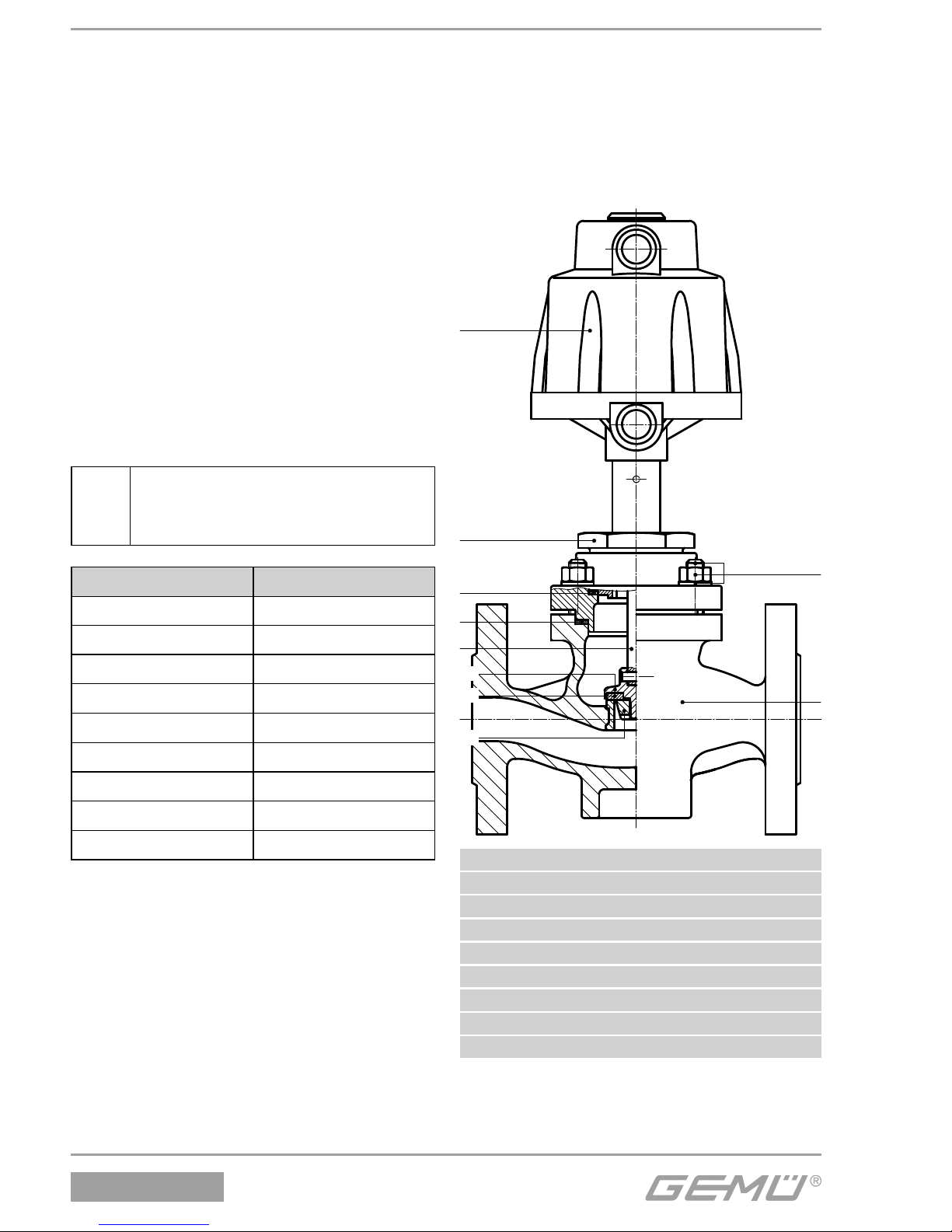
A
a
4
2
15
1
19
30
Befestigungsteile
Antriebs-
fl ansch
Ventilkörper-
fl ansch
14
1 Ventilkörper
4 Dichtring
14 Sitzdichtung
30 Dichtring
A Antrieb
a Überwurfmutter
2 Spindel
15 Ventilteller
19 Tellerscheibe
Page 6
512, 514, 532
6 / 16
2.1 Demontage Antrieb und
Dichtring 30
1. Antrieb A in Off en-Position bringen.
2. Befestigungsteile lösen und entfernen.
3. Antrieb A mit Antriebsfl ansch vom
Ventilkörperfl ansch abheben.
4. Antrieb A in Geschlossen-Position
bringen.
5. Dichtring 30 aus Ventilkörperfl ansch
entnehmen.
+
Wichtig:
Nach Demontage alle Teile von
Verschmutzungen reinigen (Teile
dabei nicht beschädigen). Teile
auf Beschädigung prüfen, ggf.
auswechseln (nur Originalteile von
GEMÜ verwenden).
2.2 Auswechseln der
Stopfbuchspackung
Messing-Ausführung Edelstahl-Ausführung
Stützring 7
V-Manschetten:
8 PTFE - hell
33 Elastomer - dunkel
Druckring 9
Druckfeder 6
Führungsbuchse 5
}
}
Ventilspindel 2
Sicherungsring 3
WARNUNG
Haube steht unter Federdruck!
® Gefahr von schwersten Verletzungen
oder Tod!
G Antrieb nur unter Presse öff nen.
1. Antrieb A demontieren wie in Kapitel
2.1, Punkte 1-5 beschrieben.
2. Antrieb A in Presse einspannen.
VORSICHT
Bruch der Haube bei zu starkem
Druck!
® Nur minimal nötigen Druck
ausüben.
3. Verbindungsschrauben zwischen
Oberteil und Unterteil des Antriebs A
lösen und entfernen.
4. Pressdruck langsam wegnehmen.
Antrieb A entlasten und öff nen.
5. Druckfedern und O-Ring 24 aus
Kolbenlaufbuchse 13 entnehmen.
6. Kolbenlaufbuchse 13 aus Oberteil des
Antriebs A ziehen und mit Dowcorning
111 Molycote einfetten.
7. Sechskantmutter 11 der Kolben-
Spindel-Verbindung im Unterteil des
Antriebs A lösen.
8. Lippenring 21 aus Kolbendeckel
entfernen.
9. O-Ring 22 zwischen Kolben und
Kolbendeckel entfernen.
10. Spindel 2 aus Unterteil des Antriebs A
nach unten heraus ziehen.
11. Lippenring 26 aus Unterteil des
Antriebs A entfernen.
12. Sicherungsring 3 im Unterteil des
Antriebs A mit geeignetem Werkzeug
(z. B. Seegerringzange) entfernen.
13. Nacheinander Führungsbuchse 5,
Druckfeder 6, Druckring 9,
V-Manschetten 8 und 33 und
Stützring 7 aus dem Rohr im Unterteil
des Antriebs A ziehen.
14. Neue Stopfbuchspackung in folgender
Reihenfolge in das Rohr im Unterteil
des Antriebs A einlegen:
1. Stützring 7
2. V-Manschetten 8 und 33 PTFE (nicht
vorhanden bei Antriebsgröße 2) /
Elastomer / PTFE / Elastomer / PTFE
(vorher fetten mit Dowcorning 111
Molycote)
Page 7
7 / 16
512, 514, 532
+
V-Manschetten 8 und 33 mit
den scharfkantigen Seiten
in Richtung Ventilkörper
anordnen, sonst keine
Dichtfunktion!
3. Druckring 9
4. Druckfeder 6
5. Führungsbuchse 5
15. Stopfbuchspackung mit Sicherungsring
3 arretieren.
16. Neuen Lippenring 26 in Unterteil des
Antriebs A einlegen.
17. Spindel 2 durch Unterteil des Antriebs A
stecken.
18. O-Ring 22 zwischen Kolben und
Kolbendeckel einlegen.
19. Neuen Lippenring 21 in Kolbendeckel
einlegen.
20. Kolben-Spindel-Verbindung im Unterteil
des Antriebs A mit Sechskantmutter 11
fi xieren.
21. Kolbenlaufbuchse 13 in Oberteil des
Antriebs A drücken.
22. O-Ring 24 und Druckfedern in
Kolbenlaufbuchse 13 einlegen.
23. Oberteil und Unterteil des
Antriebs A auf einander stecken und
Verbindungsschrauben einlegen.
24. Antrieb A in Presse einspannen,
Oberteil und Unterteil des Antriebs A
bündig auf einander pressen.
VORSICHT
Bruch der Haube bei zu starkem
Druck!
® Nur minimal nötigen Druck
ausüben.
25. Verbindungsschrauben zwischen
Oberteil und Unterteil des Antriebs A
über Kreuz festziehen.
26. Pressdruck langsam wegnehmen.
27. Antrieb A montieren wie in Kapitel 2.4,
Punkte 1-5 beschrieben.
2.3 Auswechseln der
Sitzdichtung
1. Antrieb A demontieren wie in Kapitel
2.1, Punkte 1-5 beschrieben.
2. Tellerscheibe 19 an der Spindel 2 lösen
(Spindel 2 mit geeignetem Werkzeug,
das die Spindeloberfl äche nicht
beschädigt, festhalten).
3. Sitzdichtung 14 entnehmen.
4. Alle Teile reinigen, dabei nicht
zerkratzen oder beschädigen.
5. Neue Sitzdichtung 14 einlegen.
6. Geeignetes Schraubensicherungsmittel
auf Gewinde von Ventilteller 15
auftragen.
7. Tellerscheibe 19 ansetzen (Spindel 2
mit geeignetem Werkzeug, das die
Spindeloberfl äche nicht beschädigt,
festhalten) und festziehen.
8. Antrieb A montieren wie in Kapitel 2.4,
Punkt 1-5 beschrieben.
+
Wichtig:
Austausch der Stahl-Sitzdichtung
nur durch GEMÜ. Komplettes
Ventil mit ausgefüllter
Rücksendeerklärung an GEMÜ
senden.
Page 8
512, 514, 532
8 / 16
2.4 Montage Antrieb und
Dichtring 30
1. Antrieb A in Off en-Position bringen.
2. Neuen Dichtring 30 in
Ventilkörperfl ansch einlegen.
3. Antrieb A mit Antriebsfl ansch auf
Ventilkörperfl ansch aufsetzen,
Position der Steuermediumanschlüsse
beachten.
4. Befestigungsteile handfest eindrehen
und mit geeignetem Gabelschlüssel
über Kreuz festziehen.
5. Antrieb A in Geschlossen-Position
bringen, komplett montiertes Ventil auf
Funktion und auf Dichtheit prüfen.
+
Wichtig:
Dichtring 30 bei jeder Demontage /
Montage des Antriebs
austauschen.
2.5 Austausch von Dichtring 4
1. Antrieb A in Off en-Position bringen.
2. Überwurfmutter a lösen.
3. Antrieb A vom Antriebsfl ansch abheben.
4. Dichtring 4 aus Antriebsfl ansch
entnehmen.
5. Alle Teile reinigen, dabei nicht
zerkratzen oder beschädigen!
6. Alle Teile auf Beschädigungen prüfen.
Beschädigte Teile austauschen (nur
Originalteile von GEMÜ verwenden).
7. Neuen Dichtring 4 in Antriebsfl ansch
einlegen.
8. Antrieb A auf Antriebsfl ansch aufsetzen,
so dass die Steuermediumanschlüsse
ca. 90° vor Endposition sind.
Überwurfmutter a festziehen. Dabei
dreht sich der Antrieb um ca. 90° bis zur
gewünschten Position.
9. Antrieb A in Geschlossen-Position
bringen, komplett montiertes Ventil auf
Funktion und auf Dichtheit prüfen.
+
Wichtig:
Dichtring 4 bei jeder Demontage /
Montage des Antriebs
austauschen.
Page 9
9 / 16
512, 514, 532
General information
+
Observe the installation, operating
and maintenance instructions
of GEMÜ 512, GEMÜ 514 and
GEMÜ 532! The descriptions and
instructions in these assembly
instructions apply to the standard
versions.
WARNING
The equipment is subject to pressure!
® Risk of severe injury or death!
G Only work on depressurized plant.
WARNING
The actuator cover is under spring
pressure!
® Risk of severe injury or death!
G Only open the actuator under a press.
WARNING
Corrosive chemicals!
® Risk of caustic burns!
G Wear appropriate protective
gear when installing.
CAUTION
Hot plant components!
® Risk of burns!
G Only work on plant that has
cooled down.
CAUTION
Never use the valve as a step or an aid
for climbing!
® This entails the risk of slipping-off or
damaging the valve.
CAUTION
Do not exceed the maximum
permissible pressure!
® Take precautionary measures to
avoid possible pressure surges (water
hammer).
Valve construction using
GEMÜ 514, 532 as an example
Compression
springs
Upper part of
actuator
(cover)
Piston
sleeve
13
O-ring 24
Hexagon
nut 11
Actuator base
Spindle 2
Guide
bush 5
Circlip 3
Compression
spring 6
Pressure ring 9
Support ring 7
Chevron
packings
8 and 33
O-ring
22
Lip ring
21
Lip ring 26
Pin 16
Retaining nut 19
Valve plug 15
Gasket 4
Seat seal 14
Actuator A
Valve body 1
Union nut a
Page 10
512, 514, 532
10 / 16
1 Assembly / disassembly
of gland packing for
GEMÜ 514, 532
Please refer to installation, operating and
maintenance instructions GEMÜ 514 and
GEMÜ 532 - chapter 11.1 "Installing the
valve" and chapter 20 "Sectional drawings
and spare parts".
1.1 Disassembly of actuator
and gasket 4
1. Move actuator A to the open position.
2. Loosen union nut a.
3. Remove actuator A from valve body 1.
4. Remove gasket 4.
+
Important:
After disassembly, clean all parts
of contamination (do not damage
parts). Check parts for potential
damage, replace if necessary (only
use genuine parts from GEMÜ).
1.2 Replacement of the gland
packing
Brass version Stainless steel version
Support ring 7
Chevron packings:
8 PTFE - light
33 elastomer - dark
Pressure ring 9
Compression spring 6
Guide bush 5
}
}
Valve spindle 2
Circlip 3
WARNING
The actuator cover is under spring
pressure!
® Risk of severe injury or death!
G Only open the actuator under a press.
1. Disassemble actuator A as described in
chapter 1.1, points 1-4.
2. Clamp actuator A in a press.
CAUTION
Actuator cover will break if
pressure is too high!
® Only use minimum required
pressure.
3. Loosen and remove connecting screws
between cover and base of actuator A.
4. Slowly release the press allowing the
cover of actuator A to raise under the
relaxing springs.
5. Remove compression springs and
O-ring 24 from piston sleeve 13.
6. Pull piston sleeve 13 from cover
of actuator A and lubricate with
Dowcorning 111 Molycote.
7. Loosen hexagon nut 11 of the pistonspindle connection in the base of
actuator A.
8. Remove lip ring 21 from piston cover.
9. Remove O-ring 22 between piston and
piston cover.
10. Pull out spindle 2 downwards from base
of actuator A.
11. Remove lip ring 26 from base of
actuator A.
12. Remove circlip 3 in base of actuator A
with appropriate tool (e.g. circlip pliers).
13. Pull out in the following order: guide
bush 5, compression spring 6, pressure
ring 9, chevron packings 8 and 33 and
support ring 7 from the pipe in the base
of actuator A.
14. Insert new gland packing in the
following order in the pipe in the base of
actuator A:
1. Support ring 7
2. Chevron packings 8 and 33 PTFE
(not included with actuator size 2) /
Page 11
11 / 16
512, 514, 532
elastomer / PTFE / elastomer / PTFE
(lubricate beforehand with
Dowcorning 111 Molycote)
+
Arrange the sharp-edged sides
of the chevron packings 8 and
33 in the direction of the valve
body, otherwise no sealing
tightness will be achieved!
3. Pressure ring 9
4. Compression spring 6
5. Guide bush 5
15. Lock gland packing in place with
circlip 3.
16. Insert new lip ring 26 in base of
actuator A.
17. Push spindle 2 through base of
actuator A.
18. Insert O-ring 22 between piston and
piston cover.
19. Insert new lip ring 21 in piston cover.
20. Fix piston-spindle connection in the
base of actuator A with hexagon nut 11.
21. Push piston sleeve 13 into cover of
actuator A.
22. Insert O-ring 24 and compression
springs in piston sleeve 13.
23. Put cover and base of actuator A
together and insert connecting screws.
24. Clamp actuator A in a press and press
cover and base of actuator A fl ush
together.
CAUTION
Actuator cover will break if
pressure is too high!
® Only use minimum required
pressure.
25. Tighten connecting screws between
cover and base of actuator A diagonally.
26. Slowly release the press.
27. Assemble actuator A as described in
chapter 1.4, points 1-5.
1.3 Replacement of seat seal
1. Disassemble actuator A as described in
chapter 1.1, points 1-4.
2. Loosen retaining nut 19 on spindle 2
(hold spindle 2 with appropriate tool that
will not damage the spindle surfaces).
3. Remove seat seal 14.
4. Clean all parts, do not scratch or
damage the parts during cleaning.
5. Insert new seat seal 14.
6. Apply appropriate thread locking
compound on the thread of valve
plug 15.
7. Position retaining nut 19 (hold spindle 2
with appropriate tool that will not
damage the spindle surfaces) and
tighten.
8. Assemble actuator A as described in
chapter 1.4, points 1-5.
+
Important:
Replacement of the version with
steel seat seal only by GEMÜ.
Send the complete valve with
the completed goods return
declaration to GEMÜ.
Page 12
512, 514, 532
12 / 16
1.4 Assembly of actuator and
gasket 4
1. Move actuator A to the open position.
2. Insert new gasket 4 in valve body 1.
3. Actuator rotatable 360°. Position of the
control medium connectors is optional.
4. Place actuator A on valve body 1
approx. 90° anticlockwise to the desired
end position of the control medium
connectors and screw it down hand tight
using union nut a.
5. Tightening the union nut a with an open-
end wrench (torques see table) rotates
the actuator clockwise approx. 90° to
the desired position.
6. Move actuator A to the closed position,
check function and tightness of
completely assembled valve.
+
Important:
Replace gasket 4 during every
actuator disassembly / assembly.
Nominal size Torques [Nm]
DN 10 90
DN 15 90
DN 20 100
DN 25 120
DN 32 120
DN 40 150
DN 50 200
DN 65 260
DN 80 280
2 Assembly / disassembly of
gland packing for GEMÜ 512
Please refer to installation, operating and
maintenance instructions GEMÜ 512 chapter 11.1 "Installing the valve" and
chapter 20 "Sectional drawings and spare
parts".
A
a
4
2
1
30
Mounting parts
Actuator
fl ange
Valve body
fl ange
15
19
14
1 Valve body
4 Gasket
14 Seat seal
30 Gasket
A Actuator
a Union nut
2 Spindle
15 Valve plug
19 Retaining nut
Page 13
13 / 16
512, 514, 532
2.1 Disassembly of actuator
and gasket 30
1. Move actuator A to the open position.
2. Loosen and remove mounting parts.
3. Lift off actuator A with actuator fl ange
from valve body fl ange.
4. Move actuator A to the closed position.
5. Remove gasket 30 from valve body
fl ange.
+
Important:
After disassembly, clean all parts
of contamination (do not damage
parts). Check parts for potential
damage, replace if necessary (only
use genuine parts from GEMÜ).
2.2 Replacement of the gland
packing
Brass version Stainless steel version
Support ring 7
Chevron packings:
8 PTFE - light
33 elastomer - dark
Pressure ring 9
Compression spring 6
Guide bush 5
}
}
Valve spindle 2
Circlip 3
WARNING
The actuator cover is under spring
pressure!
® Risk of severe injury or death!
G Only open the actuator under a press.
1. Disassemble actuator A as described in
chapter 2.1, points 1-5.
2. Clamp actuator A in a press.
CAUTION
Actuator cover will break if
pressure is too high!
® Only use minimum required
pressure.
3. Loosen and remove connecting screws
between cover and base of actuator A.
4. Slowly release the press allowing the
cover of actuator A to raise under the
relaxing springs.
5. Remove compression springs and
O-ring 24 from piston sleeve 13.
6. Pull piston sleeve 13 from cover
of actuator A and lubricate with
Dowcorning 111 Molycote.
7. Loosen hexagon nut 11 of the pistonspindle connection in the base of
actuator A.
8. Remove lip ring 21 from piston cover.
9. Remove O-ring 22 between piston and
piston cover.
10. Pull out spindle 2 downwards from base
of actuator A.
11. Remove lip ring 26 from base of
actuator A.
12. Remove circlip 3 in base of actuator A
with appropriate tool (e.g. circlip pliers).
13. Pull out in the following order: guide
bush 5, compression spring 6, pressure
ring 9, chevron packings 8 and 33 and
support ring 7 from the pipe in the base
of actuator A.
14. Insert new gland packing in the
following order in the pipe in the base of
actuator A:
1. Support ring 7
2. Chevron packings 8 and 33 PTFE
(not included with actuator size 2) /
elastomer / PTFE / elastomer / PTFE
(lubricate beforehand with
Dowcorning 111 Molycote)
Page 14
512, 514, 532
14 / 16
+
Arrange the sharp-edged sides
of the chevron packings 8 and
33 in the direction of the valve
body, otherwise no sealing
tightness will be achieved!
3. Pressure ring 9
4. Compression spring 6
5. Guide bush 5
15. Lock gland packing in place with
circlip 3.
16. Insert new lip ring 26 in base of
actuator A.
17. Push spindle 2 through base of
actuator A.
18. Insert O-ring 22 between piston and
piston cover.
19. Insert new lip ring 21 in piston cover.
20. Fix piston-spindle connection in the
base of actuator A with hexagon nut 11.
21. Push piston sleeve 13 into cover of
actuator A.
22. Insert O-ring 24 and compression
springs in piston sleeve 13.
23. Put cover and base of actuator A
together and insert connecting screws.
24. Clamp actuator A in a press and press
cover and base of actuator A fl ush
together.
CAUTION
Actuator cover will break if
pressure is too high!
® Only use minimum required
pressure.
25. Tighten connecting screws between
cover and base of actuator A diagonally.
26. Slowly release the press.
27. Assemble actuator A as described in
chapter 2.4, points 1-5.
2.3 Replacement of seat seal
1. Disassemble actuator A as described in
chapter 2.1, points 1-5.
2. Loosen retaining nut 19 on spindle 2
(hold spindle 2 with appropriate tool that
will not damage the spindle surfaces).
3. Remove seat seal 14.
4. Clean all parts, do not scratch or
damage the parts during cleaning.
5. Insert new seat seal 14.
6. Apply appropriate mounting glue on the
thread of valve plug 15.
7. Position retaining nut 19 (hold spindle 2
with appropriate tool that will not
damage the spindle surfaces) and
tighten.
8. Assemble actuator A as described in
chapter 2.4, points 1-5.
+
Important:
Replacement of the version with
steel seat seal only by GEMÜ.
Send the complete valve with
the completed goods return
declaration to GEMÜ.
Page 15
15 / 16
512, 514, 532
2.4 Assembly of actuator and
gasket 30
1. Move actuator A to the open position.
2. Insert new gasket 30 in valve body
fl ange.
3. Place actuator A with actuator fl ange
on valve body fl ange, pay attention
to the position of the control medium
connectors.
4. Screw in mounting parts hand tight
and tighten diagonally with appropriate
open-end wrench.
5. Move actuator A to the closed position,
check function and tightness of
completely assembled valve.
+
Important:
Replace gasket 30 during every
actuator disassembly / assembly.
2.5 Replacement of gasket 4
1. Move actuator A to the open position.
2. Loosen union nut a.
3. Lift off actuator A from actuator fl ange.
4. Remove gasket 4 from actuator fl ange.
5. Clean all parts, do not scratch or
damage the parts during cleaning.
6. Check all parts for potential damage.
Replace damaged parts (only use
genuine parts from GEMÜ).
7. Insert new gasket 4 in actuator fl ange.
8. Place actuator A on actuator fl ange so
that the control medium connectors are
approx. 90° before the end position.
Tightening union nut a rotates the
actuator approx. 90° to the desired
position.
9. Move actuator A to the closed position,
check function and tightness of
completely assembled valve.
+
Important:
Replace gasket 4 during every
actuator disassembly / assembly.
Page 16

GEMÜ Gebr. Müller Apparatebau GmbH & Co. KG · Fritz-Müller-Str. 6-8 · D-74653 Ingelfi ngen-Criesbach
Telefon +49(0)7940/123-0 · Telefax +49(0)7940/123-192 · [email protected] · www.gemu-group.com
Änderungen vorbehalten · Subject to alteration · 08/2014 · 88373711
VENTIL-, MESS- UND REGELSYSTEME
VALVES, MEASUREMENT AND CONTROL SYSTEMS
 Loading...