

Page 1
1436 cPos
®
1436 cPos
®
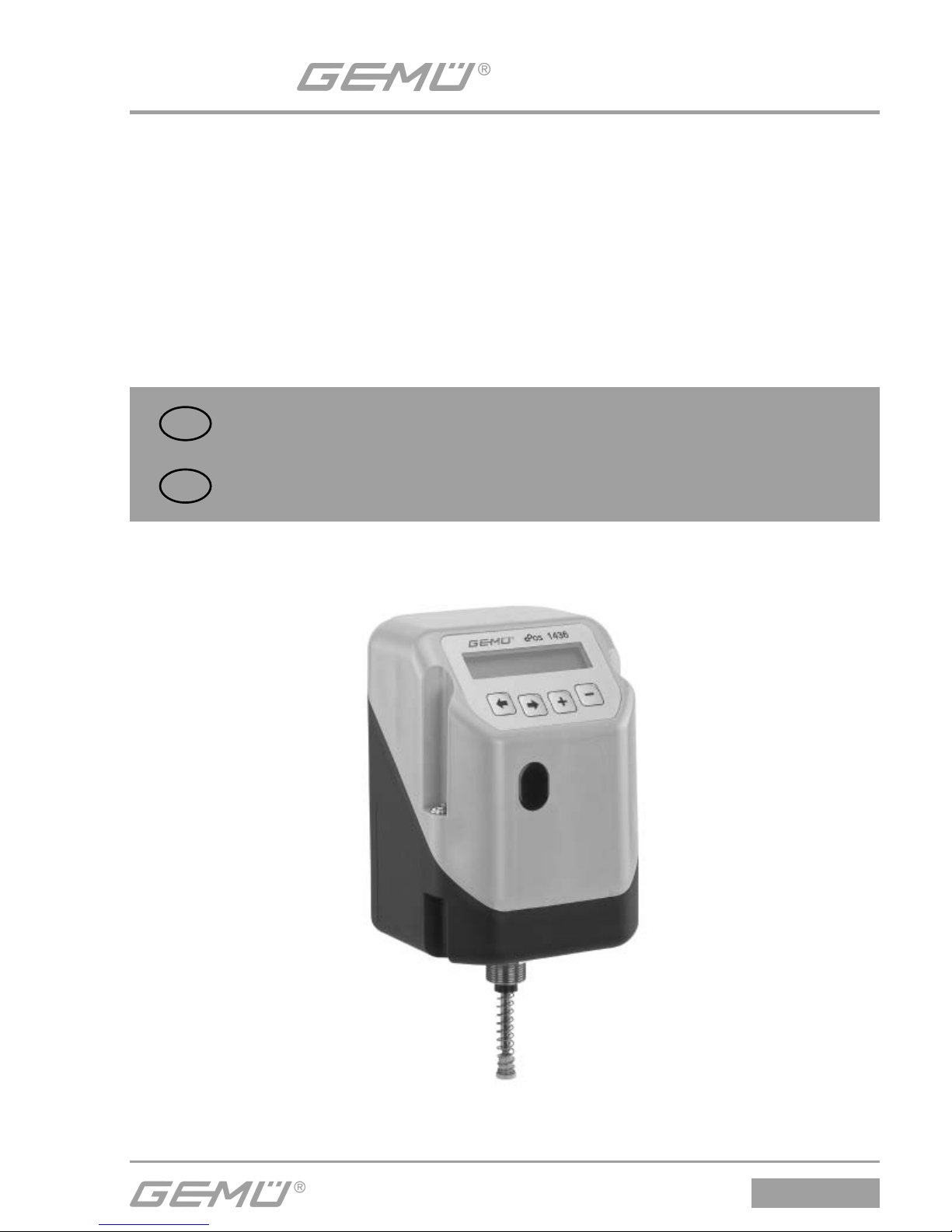
Intelligenter Stellungsregler
ORIGINAL QUICK GUIDE
DE
Ab Version /
Intelligent Positioner
QUICK GUIDE
GB
from version 2.0.3.0
Page 2
1436 cPos
®
2 / 24
Inhaltsverzeichnis
1 Hinweise zu Ihrer Sicherheit 2
2 Mechanischer Anbau 2
2.1 Anbau an Hubantriebe 2
2.1.1 Vorbereitung des Ventilantriebs 2
2.1.2 Komplettierung des Weggebers 2
2.1.3 Anbau des Stellungsreglers 3
2.2 Anbau an Schwenkantriebe 3
2.2.1 Vorbereitung des Ventilantriebs 3
2.2.2 Komplettierung des Weggebers 3
2.2.3 Anbau des Stellungsreglers 4
2.2.4 Überprüfung des
mechanischen Anbaus 4
2.3 Externer Anbau an Hub oder Schwenkantriebe 4
2.3.1 Vorbereitung des Ventilantriebs 4
2.3.2 Komplettierung des Weggebers 4
2.3.3 Überprüfung des
mechanischen Anbaus 4
2.3.4 Anbau des Haltewinkels 4
2.3.5 Anschluss des Weggebers 5
3 Pneumatische Anschlüsse 5
4 Elektrische Anschlüsse 5
4.1 Standard 5
4.2 Profibus DP 6
4.3 DeviceNet 6
4.4 Anschlussbelegung M12-Stecker
für externen Weggeber 6
5 Initialisierung und
Inbetriebnahme 12
5.1 Elektrischer und pneumatischer
Anschluss 12
6 Menüstruktur 14
6.1 Menüstruktur 1. Service 14
6.2 Menüstruktur 2. SetBasics 16
6.3 Menüstruktur 3. SetFunction 18
6.4 Menüstruktur 4. SetCalibration 20
6.5 Menüstruktur 5. Communication 22
1 Hinweise zu Ihrer
Sicherheit
Die Sicherheitshinweise entnehmen Sie
bitte der Bedienungsanleitung des GEMÜ
1436 cPos
®
auf der beiliegenden CD-ROM.
Sollten Sie nicht im Besitz dieser CD-ROM
sein, wenden Sie sich bitte an GEMÜ.
2 Mechanischer Anbau
2.1 Anbau an Hubantriebe
2.1.1 Vorbereitung des Ventilantriebs
G Antrieb muss sich in Grundstellung
(Antrieb entlüftet) befi nden.
G Befi ndet sich im Antrieb oben eine
optische Sichtanzeige (rote Spindel),
dann diese herausziehen.
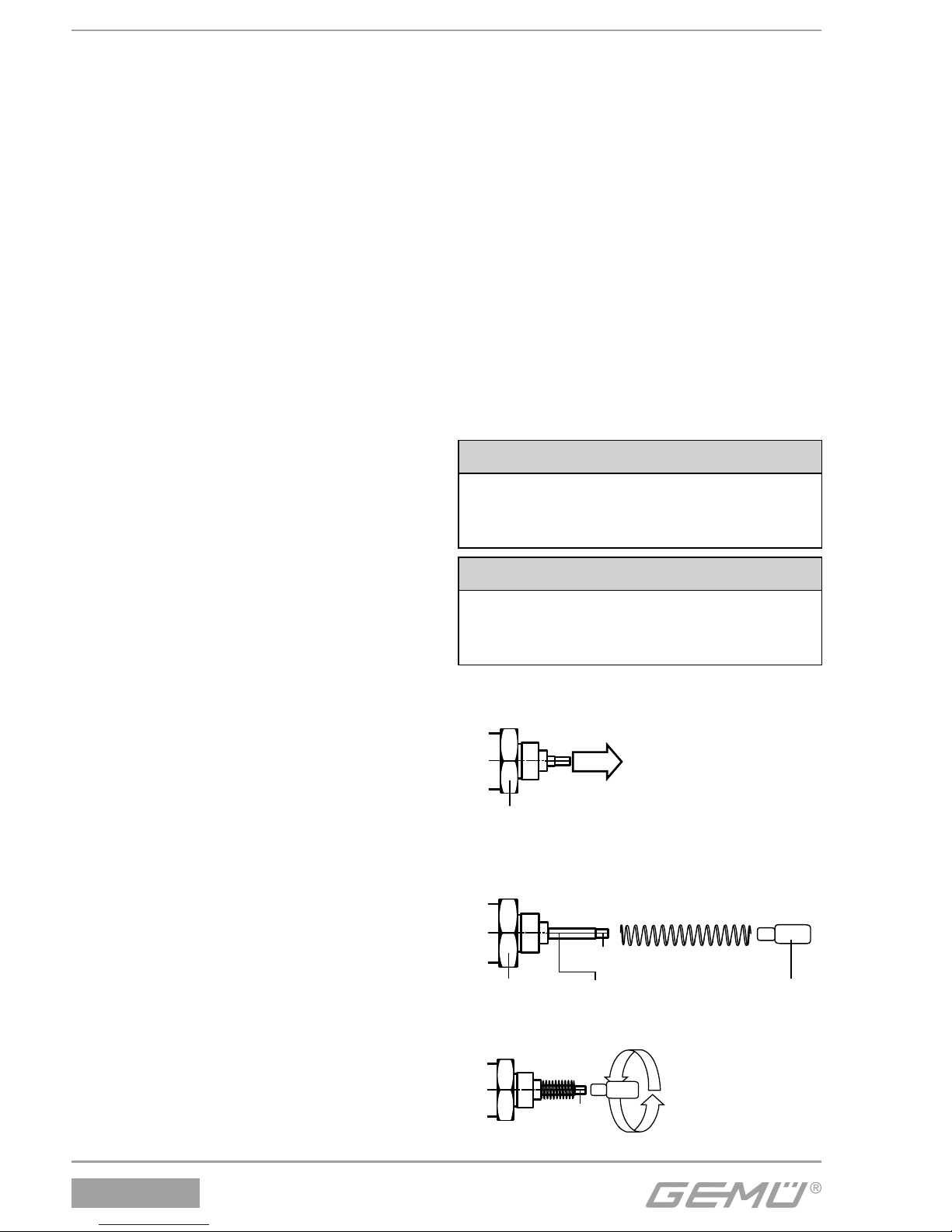
2.1.2 Komplettierung des Weggebers
Der Weggeber wird mit einem
Anbausatz 1436S01Z..., bestehend aus
Druckfeder, Betätigungsspindel und evtl.
Gewindeadapter komplettiert.
Der Anbausatz ist ventilspezifi sch.
VORSICHT
Vorgespannte Feder!
® Beschädigung des Gerätes.
● Feder langsam entspannen.
VORSICHT
Eine Beschädigung der Spindeloberfl äche kann zum Ausfall des
Weggebers führen!
1. Spindel aus Weggeber bis Anschlag
heraus ziehen.
Weggeber
2. Druckfeder über Spindel schieben.
3. Spindel an Punkt a fi xieren (Spindel
darf dabei nicht beschädigt werden).
Weggeber Spindel
a Druckfeder
Betätigungsspindel
4. Betätigungsspindel auf Spindel
aufschrauben.
a
Page 3
1436 cPos
®
3 / 24
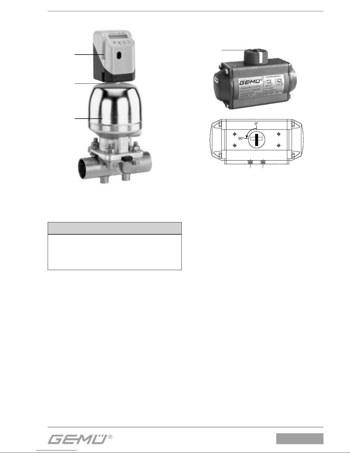
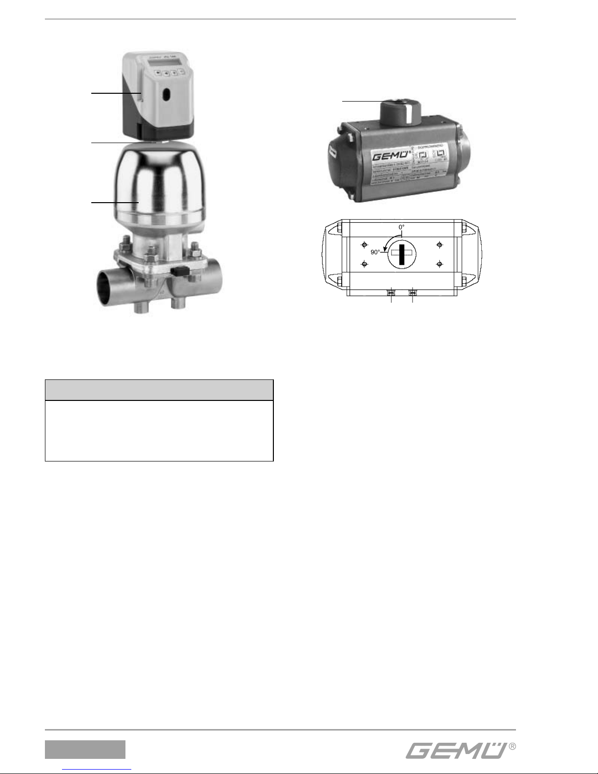
2.1.3 Anbau des Stellungsreglers
1
2
3
G Stellungsregler 1 durch einschrauben
des Weggeber-Sechskants M27 2 in
Antrieb 3 einschrauben.
VORSICHT
Der Regler darf nicht durch Drehen des
Gehäuses befestigt werden, da sonst
die Gefahr besteht dass der interne
Anschlag überdreht wird!
Der Stellungsregler lässt sich nach
korrektem Anbau auf das entsprechende
Ventil um 370° drehen.
2.2 Anbau an Schwenkantriebe
2.2.1 Vorbereitung des Ventilantriebs
6
ZU
AUF
G Antrieb muss sich in Grundstellung
(Antrieb entlüftet) befi nden. Bei
doppeltwirkenden Antrieben sollte der
Antrieb in Geschlossen-Position gebracht
werden.
G Schraube 6 zur Befestigung der
optischen Sichtanzeige entfernen.
G Drehrichtung des Antriebs ermitteln
(die Drehrichtung des Antriebs muss
von oben betrachtet gegen den
Uhrzeigersinn sein, wenn der Antrieb von
der Geschlossen-Position in die Off en-
Position fährt).
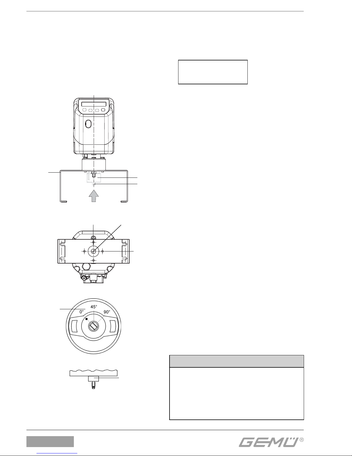
2.2.2 Komplettierung des Weggebers
G Vor der Montage an den Antrieb darauf
achten, dass die Wellenhöhe und das
Lochbild des Antriebs mit den Maßen des
Haltewinkels 1 übereinstimmen.
G Die Welle des Weggebers ist mit einer
Markierung 2 versehen. Stimmt diese
Markierung mit der Markierung auf der
Unterseite des Weggebergehäuses 3
überein, so befi ndet sich der Weggeber in
der 0° Stellung.
G Der elektrische Drehbereich befi ndet sich
90° im Uhrzeigersinn von dieser Stellung.
Page 4
1436 cPos
®
4 / 24
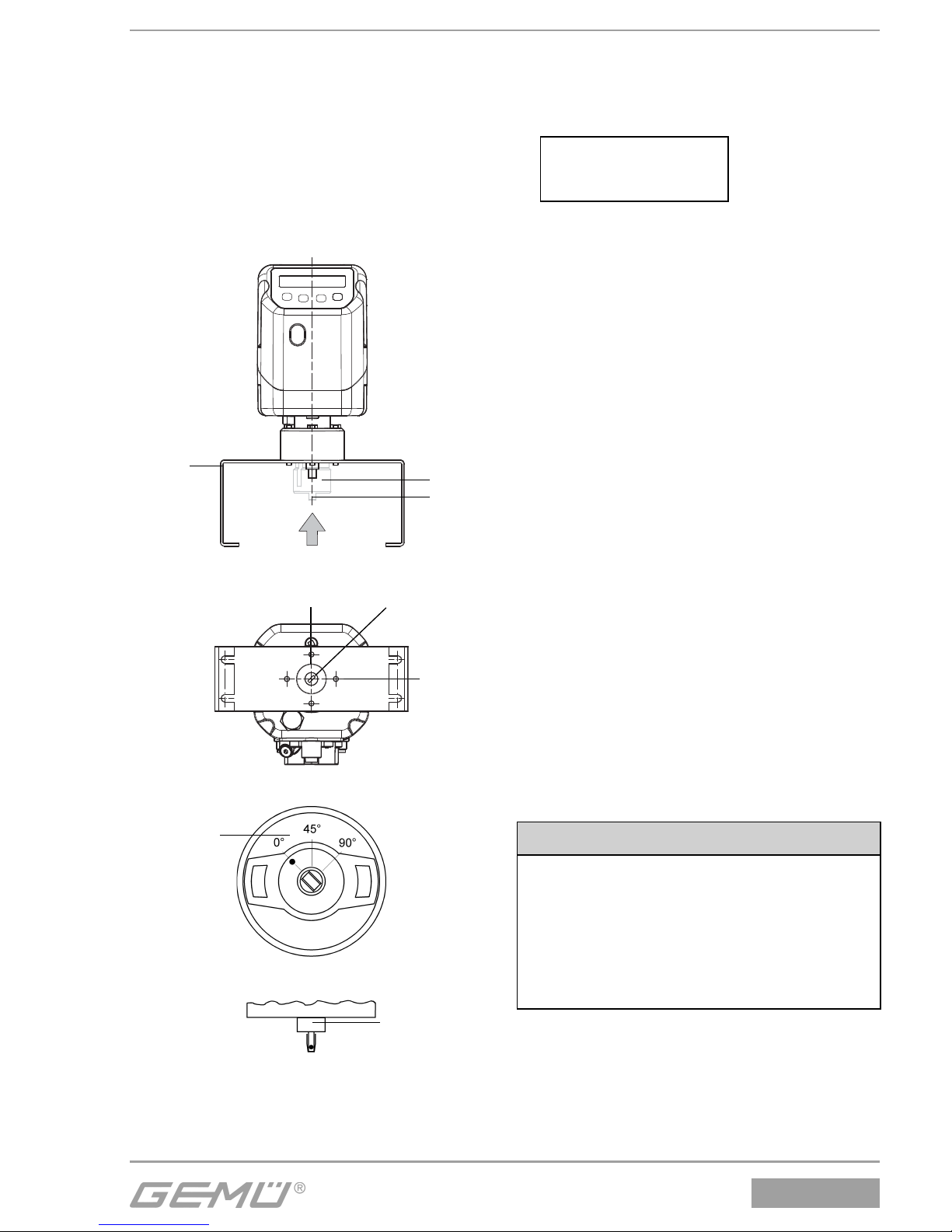
2.2.3 Anbau des Stellungsreglers
G Adapter 4 auf Welle des Weggebers
setzen.
G Stellungsregler mit Weggeber und
Haltewinkel auf Antrieb aufsetzen.
G Nase von Adapter 5 muss in Nut von
Antriebswelle einrasten.
G Haltewinkel 1 mit beiliegenden
Schrauben auf Antrieb befestigen.
Ansicht X
1
4
5
90°
45°0°
Ansicht X mit Adapter
3
Ansicht X nur Weggeber
2
Weggeber mit Markierung
2.2.4 Überprüfung des mechanischen
Anbaus
G Stellungsregler an Versorgungsspannung
und Luftversorgung anschließen.
G Im Display erscheint folgende Meldung:
NoInit XX.X%
Mit Hilfe der + und - Tasten kann der
angebaute Antrieb in die Stellung AUF und
ZU gefahren werden.
Dabei muss die Anzeige der Ventilstellung
zwischen 0 % und 100 % liegen.
Sollte die Anzeige den Bereich zwischen
0 % und 100 % verlassen, ist der
mechanische Anbau noch einmal zu
überprüfen.
2.3 Externer Anbau an Hub- oder
Schwenkantriebe
2.3.1 Vorbereitung des Ventilantriebs
Siehe Kapitel 2.1.1 oder 2.2.1.
2.3.2 Komplettierung des Weggebers
Siehe Kapitel 2.1.2 oder 2.2.2.
2.3.3 Überprüfung des mechanischen
Anbaus
Siehe Kapitel 2.2.4.
2.3.4 Anbau des Haltewinkels
G Verbindungsadapter des Stellungsreglers
durch Bohrung des Haltewinkels
schieben und mit beiliegender Mutter
fi xieren.
G Haltewinkel mit Hilfe der Bohrungen und
geeignetem Befestigungsmaterial an
einer festen Stelle anschrauben.
VORSICHT
Auf ausreichende Festigkeit der
Befestigungsunterlage achten.
Regler muss unbedingt vor
mechanischer Belastung seitens des
Betreibers geschützt werden.
Regler nicht als Steighilfe benutzen.
Page 5
1436 cPos
®
5 / 24
2.3.5 Anschluss des Weggebers
Den 5-poligen M12-Stecker des Weggebers
mit der 5-poligen M12-Buchse des Reglers
verbinden.
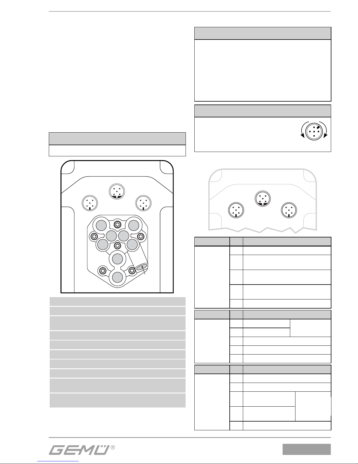
3 Pneumatische Anschlüsse
G Verbindung zwischen pneum.
Stellungsreglerausgang A1
(einfachwirkend) bzw. A1 und
A2 (doppeltwirkend) und pneum.
Steuerlufteingang des Antriebs herstellen.
G Hilfsenergie (Zuluft) an Anschluss P*
anschließen (max. 7 bar bzw. 101 psi).
VORSICHT
Max. Steuerdruck des Antriebs beachten!
1
5
43
2
1
5
43
2
1
5
43
2
1
V2
3
V5
V1
V4
V3
2
4
Anschluss Bezeichnung
1 Versorgungsluftanschluss P
3
Entlüftungsanschluss G1/8
mit Schalldämpfer
V1 Zuluft-Drossel für A1
V2 Abluft-Drossel für A1
V3 Abluft-Drossel für A2
V4 Zuluft-Drossel für A2
V5 Rückschlagventil
2
Arbeitsanschluss für Prozessventil
Stf. 1 und 2 (A1)
4
Arbeitsanschluss für Prozessventil
Stf. 3 (A2)
Alle Pneumatikanschlüsse sind G1/8
4 Elektrische Anschlüsse
VORSICHT
G Analogeingang (Sollwerteingang)
0/4-20 mA an Stecker X3 anschließen.
G Versorgungsspannung 24 V DC an
Stecker X1 anschließen.
G Bei Betrieb als Prozessregler Ana-
logeingang (Istwerteingang) 0/420 mA an Stecker X3 anschließen.
VORSICHT
Kabelbruchgefahr!
® Beschädigung des Gerätes.
● Elektrische Anschlüsse um
maximal 360° verdrehen.
1
4
3
2
5
max. 360°
4.1 Standard
X1 X3
X2
1
5
43
2
1
5
43
2
1
5
43
2
Anschluss Pin Signalname
X1
M12-Stecker
A-Kodierung
1 Uv, 24 V DC Versorgungsspannung
2
Schaltausgang K1, 24 V DC
(schaltet Uv*)
3
GND (Versorgungsspannung,
DigIn1+2+W+X; K1+2)
4
Schaltausgang K2, 24 V DC
(schaltet Uv*)
5 Digitaleingang 1 (optional**)
Anschluss Pin Signalname
X2
M12-Stecker
B-Kodierung
1 I+, Istwertausgang
2 I-, Istwertausgang
3 RxD, Receive Data, RS232
4 TxD, Transmit Data, RS232
5 GND, RS232
4-20 mA intern
versorgt; aktiv
}
Anschluss Pin Signalname
X3
M12-Stecker
A-Kodierung
1 W+, Sollwerteingang
2 W-, Sollwerteingang / Digital In W**
3
X+, ProzessIstwerteingang
4
X-, Prozess-Istwerteingang / Digital In X**
5 Digitaleingang 2 (optional**)
bei Betrieb
als Prozessregler
}
Page 6
1436 cPos
®
6 / 24
* Schaltausgang schaltet Geräteversorgungsspannung
Uv - Dropspannung
** Bei Optionen Code 01 und 03
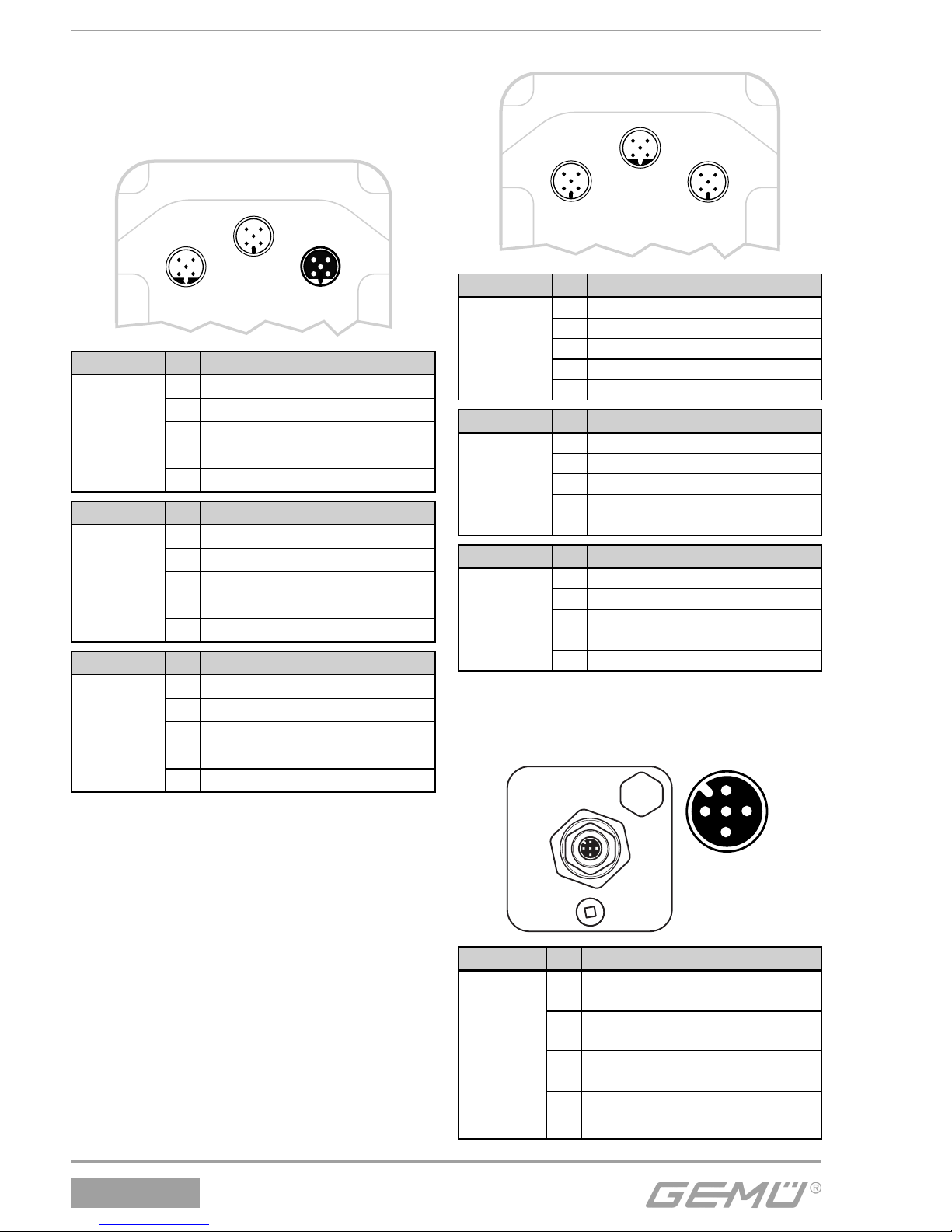
4.2 Profibus DP
X1 X3
X2
1
5
43
2
1
5
43
2
1
5
43
2
Anschluss Pin Signalname
X1
M12-Stecker
B-Kodierung
1 n.c.
2 RxD/TxD-N (PB-)
3 n.c.
4 RxD/TxD-P (PB+)
5 Schirm
Anschluss Pin Signalname
X2
M12-Stecker
A-Kodierung
1 Uv, Versorgungsspannung
2 n.c.
3 GND
4 n.c.
5 n.c.
Anschluss Pin Signalname
X3
M12-Buchse
B-Kodierung
1 BUS-V DC, +5 V DC (PB_5 V)
2 RxD/TxD-N (PB-)
3 GND (PB_GND)
4 RxD/TxD-P (PB+)
5 Schirm
4.3 DeviceNet
X1 X3
X2
1
5
43
2
1
5
43
2
1
5
43
2
Anschluss Pin Signalname
X1
M12-Stecker
A-Kodierung
1 Uv, Versorgungsspannung
2 n.c.
3 GND
4 n.c.
5 n.c.
Anschluss Pin Signalname
X2
M12-Stecker
B-Kodierung
1 n.c.
2 n.c.
3 n.c.
4 n.c.
5 n.c.
Anschluss Pin Signalname
X3
M12-Stecker
A-Kodierung
1 Schirm
2V+
3V4 Can H
5 Can L
4.4 Anschlussbelegung M12Stecker für externen
Weggeber
X4
1
5
4
3
2
X4
Anschluss Pin Signalname
X4
M12Buchse
A-Kodierung
1
U+, Ausgang Potentiometer
Versorgungsspannung (+)
2
UP, Eingang
Potentiometerschleiferspannung
3
UP-, Ausgang Potentiometer
Versorgungsspannung (-)
4 n.c.
5 n.c.
Page 7

1436 cPos
®
7 / 24
Contents
1 Notes for your safety 7
2 Mechanical mounting 7
2.1 Mounting to linear actuators 7
2.1.1 Preparation of the valve actuator 7
2.1.2 Assembling the travel sensor 7
2.1.3 Mounting the positioner 8
2.2 Mounting to quarter turn actuators 8
2.2.1 Preparation of the valve actuator 8
2.2.2 Assembling the travel sensor 8
2.2.3 Mounting the positioner 9
2.2.4 Checking the mounted assembly 9
2.3 Remote mounting to linear or
quarter turn actuators 9
2.3.1 Preparation of the valve actuator 9
2.3.2 Assembling the travel sensor 9
2.3.3 Checking the mounted assembly 9
2.3.4 Mounting the mounting bracket 9
2.3.5 Connecting the travel sensor 9
3 Pneumatic connections 10
4 Electrical connections 10
4.1 Standard 10
4.2 Profibus DP 11
4.3 DeviceNet 11
4.4 Connection assignment of M12
plug for external travel sensor 11
5 Initialisation and commissioning 12
5.1 Electrical and pneumatic
connection 12
6 Menu structure 14
6.1 Menu structure
1. Service 14
6.2 Menu structure
2. SetBasics 16
6.3 Menu structure
3. SetFunction 18
6.4 Menu structure
4. SetCalibration 20
6.5 Menu structure
5. Communication 22
1 Notes for your safety
Please refer to the safety notes included
in the GEMÜ 1436 cPos
®
operating
instructions on the enclosed CD-ROM.
If you do not have this CD-ROM, please
contact GEMÜ.
2 Mechanical mounting
2.1 Mounting to linear actuators
2.1.1 Preparation of the valve actuator
G The actuator must be in the zero position
(actuator vented).
G Should there be an optical position
indicator in the actuator (a red spindle), it
must be removed.
2.1.2 Assembling the travel sensor
The travel sensor is assembled using a
mounting kit 1436S01Z... consisting of a
spring, an operating bush and a threaded
adapter (if applicable).
The mounting kit depends on the valve type.
CAUTION
Pretensioned spring!
® Damage to the device.
● Slowly relax spring.
CAUTION
Damage to the spindle surface may
lead to failure of the travel sensor!
1. Pull out the spindle of the travel sensor
up to the limit stop.
Travel sensor
2. Push the spring over the spindle.
3. Fix the spindle at point a - (the spindle
must not be damaged during this
process).
Travel sensor Spindle
a Spring
Operating bush
4. Screw the operating bush onto the
spindle.
a
Page 8
1436 cPos
®
8 / 24
2.1.3 Mounting the positioner
1
2
3
G Mount the positioner 1 by screwing the
travel sensor hexagonal nut M27 2 into
the actuator 3.
CAUTION
The positioner must not be fi xed
by turning the housing as this may
result in the danger of overturning the
internal stop!
If correctly mounted to the valve, the
positioner can be turned 370°.
2.2 Mounting to quarter turn
actuators
2.2.1 Preparation of the valve actuator
6
CLOSED
OPEN
G
The actuator must be in the zero
position (actuator vented). Double acting
actuators should be moved to the valve
"CLOSED" position.
G Remove the screw 6 which retains the
optical position indicator.
G Determine the turn direction of the
actuator (seen from above the turn
direction of the actuator must be
anticlockwise, when the actuator moves
from the "CLOSED" to the "OPEN"
position).
2.2.2 Assembling the travel sensor
G Before mounting the travel sensor to the
actuator, make sure that the shaft height
and the hole pattern in the actuator match
the dimensions of the mounting bracket 1.
G The travel sensor shaft 2 is marked. If this
marking corresponds with the marking at
the bottom of the travel sensor housing 3,
the travel sensor is in the 0° position.
G The electrical turn range is 90° clockwise
of this position.
Page 9
1436 cPos
®
9 / 24
2.2.3 Mounting the positioner
G Place the adapter 4 on the shaft of the
travel sensor.
G Place the positioner with the travel sensor
and mounting bracket onto the actuator.
G The adapter lug 5 must engage in the
actuator shaft groove.
G Attach the mounting bracket 1 to the
actuator with the enclosed screws.
View X
1
4
5
90°
45°0°
View X with adapter
3
View X only travel sensor
2
Travel sensor with marking
2.2.4 Checking the mounted assembly
G Connect the positioner to power and air
supply.
G The following message is displayed:
NoInit XX.X%
The mounted actuator can be moved to the
OPEN and CLOSED positions using the +
and - keys.
The displayed valve position must be
between 0 % and 100 %.
If the displayed valve position is not within
the range of 0 % and 100 %, the mechanical
mounting must be checked again.
2.3 Remote mounting to linear or
quarter turn actuators
2.3.1 Preparation of the valve actuator
See chapter 2.1.1 or 2.2.1.
2.3.2 Assembling the travel sensor
See chapter 2.1.2 or 2.2.2.
2.3.3 Checking the mounted assembly
See chapter 2.2.4.
2.3.4 Mounting the mounting bracket
G Push the positioner connection adapter
through the hole in the mounting bracket
and attach it with the enclosed nut.
G Use the bolt holes and appropriate fi xings
to attach the mounting bracket securely.
CAUTION
Ensure adequate stability of the base
used for attachment.
The positioner must be protected
against mechanical stress by the
operator.
Do not use the positioner as a climbing
support.
2.3.5 Connecting the travel sensor
The 5-pin M12 travel sensor plug must
be connected to the 5-pin M12 positioner
socket.
Page 10
1436 cPos
®
10 / 24
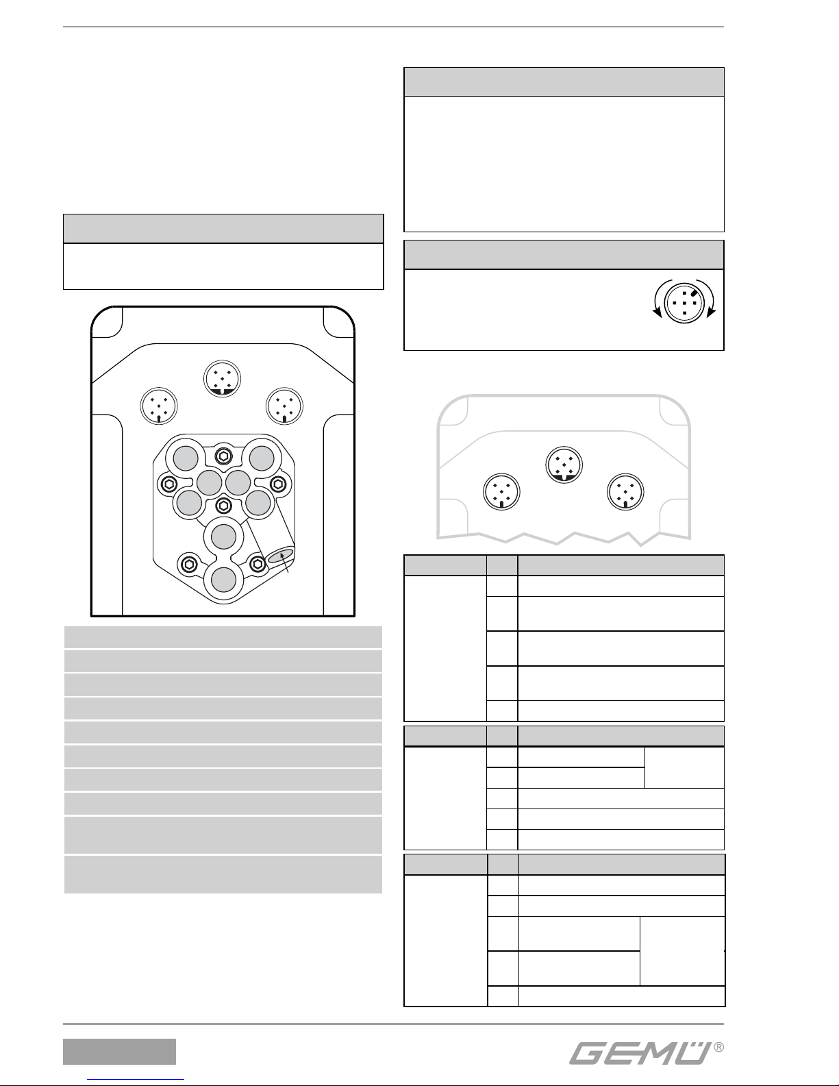
3 Pneumatic connections
G Make the connection between pneumatic
positioner outlet A1 (single acting) or
A1 and A2 (double acting) and the
pneumatic actuator air control inlet.
G Connect the control air supply (additional
air) to connection P* (max. 7 bar or
101 psi).
CAUTION
Observe maximum actuator control
pressure!
1
5
43
2
1
5
43
2
1
5
43
2
1
V2
3
V5
V1
V4
V3
2
4
Connection Description
1 Air supply connector P
3 Venting connection G1/8 with silencer
V1 Additional air throttle for A1
V2 Outgoing air throttle for A1
V3 Outgoing air throttle for A2
V4 Additional air throttle for A2
V5 Non-return valve
2 Working connection for process valve
c.f. 1 and 2 (A1)
4 Working connection for process valve
c.f. 3 (A2)
All pneumatic connectors are G1/8
4 Electrical connections
CAUTION
G Connect analogue input (set value
input) 0/4-20 mA to plug X3.
G Connect supply voltage 24 V DC to
plug X1.
G If operating as a process controller,
connect analogue input (actual
value input) 0/4-20 mA to plug X3.
CAUTION
Danger of cable break!
® Damage to the device.
● Turn electrical connections
max. 360°.
1
4
3
2
5
max. 360°
4.1 Standard
X1 X3
X2
1
5
43
2
1
5
43
2
1
5
43
2
Connection Pin Signal name
X1
M12 plug
A coding
1 Uv, 24 V DC supply voltage
2
Switching output K1, 24 V DC
(switches Uv*)
3
GND, (supply voltage,
DigIn1+2+W+X; K1+2)
4
Switching output K2, 24 V DC
(switches Uv*)
5 Digital input 1 (optional**)
Connection Pin Signal name
X2
M12 plug
B coding
1 I+, actual value output
2 I-, actual value output
3 RxD, Receive Data, RS232
4 TxD, Transmit Data, RS232
5 GND, RS232
4-20 mA
internal supply; active
}
Connection Pin Signal name
X3
M12 plug
A coding
1 W+, set value input
2 W-, set value input / Digital In W**
3
X+, process actual
value input
4
X-, process actual value input /
Digital In X**
5 Digital input 2 (optional**)
Working as
a process
controller
}
Page 11
1436 cPos
®
11 / 24
* Switching output switches device supply voltage Uv -
drop voltage
** For options code 01 and 03
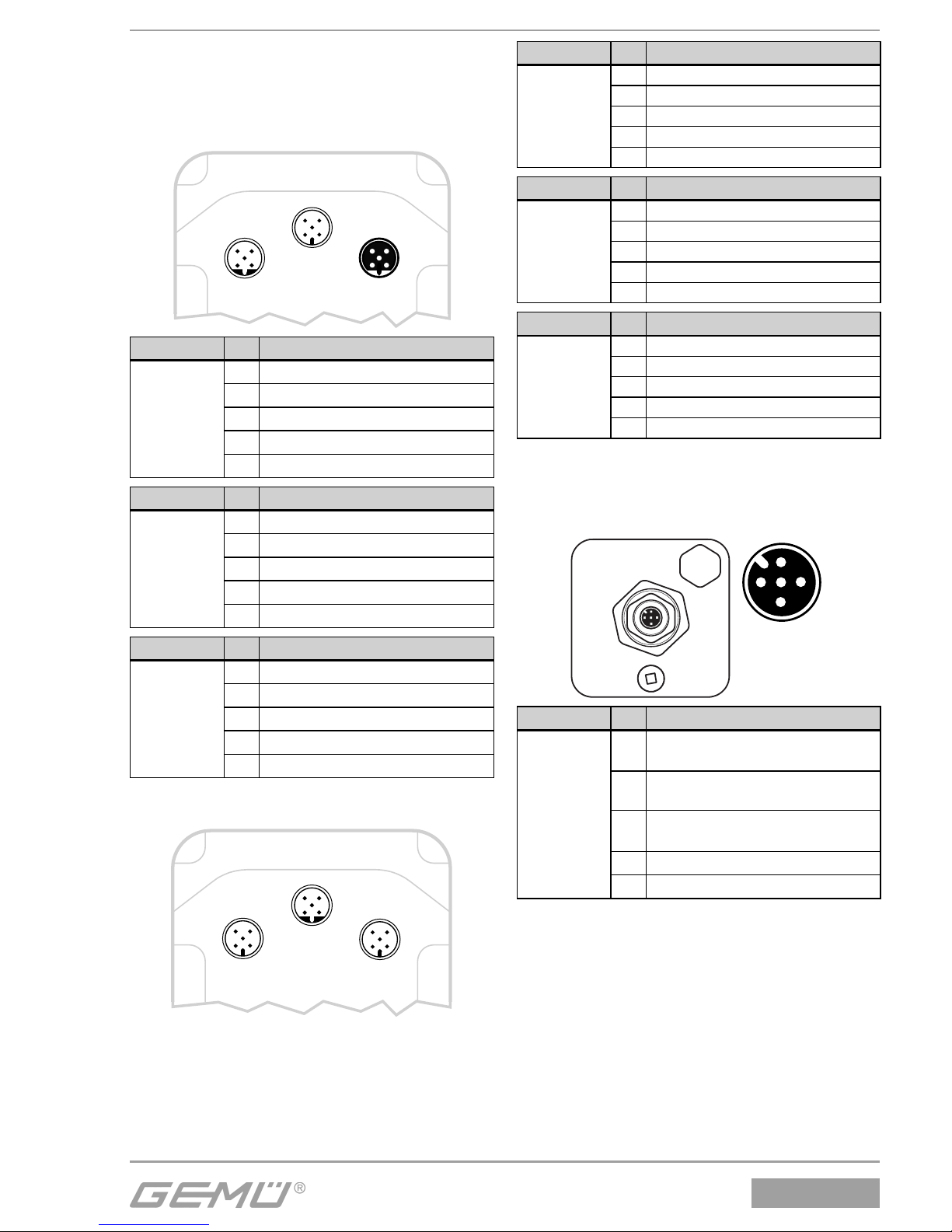
4.2 Profibus DP
X1 X3
X2
1
5
43
2
1
5
43
2
1
5
43
2
Connection Pin Signal name
X1
M12 plug
B coding
1 n.c.
2 RxD/TxD-N (PB-)
3 n.c.
4 RxD/TxD-P (PB+)
5 Shield
Connection Pin Signal name
X2
M12 plug
A coding
1 Uv, supply voltage
2 n.c.
3 GND
4 n.c.
5 n.c.
Connection Pin Signal name
X3
M12 socket
B coding
1 BUS-V DC, +5 V DC (PB_5 V)
2 RxD/TxD-N (PB-)
3 GND (PB_GND)
4 RxD/TxD-P (PB+)
5 Shield
4.3 DeviceNet
X1 X3
X2
1
5
43
2
1
5
43
2
1
5
43
2
Connection Pin Signal name
X1
M12 plug
A coding
1 Uv, supply voltage
2 n.c.
3 GND
4 n.c.
5 n.c.
Connection Pin Signal name
X2
M12 plug
B coding
1 n.c.
2 n.c.
3 n.c.
4 n.c.
5 n.c.
Connection Pin Signal name
X3
M12 plug
A coding
1 Shield
2V+
3V4 Can H
5 Can L
4.4 Connection assignment of
M12 plug for external travel
sensor
X4
1
5
4
3
2
X4
Connection Pin Signal name
X4
M12 socket
A coding
1
UP+, output potentiometer supply
voltage (+)
2
UP, input potentiometer wiper
voltage
3
UP-, output potentiometer supply
voltage (-)
4 n.c.
5 n.c.
Page 12
1436 cPos
®
12 / 24
5 Initialisierung und
Inbetriebnahme
Durch das Starten der Selbstinitialisierung
passt sich der Regler an das Ventil an.
Sämtliche Parameter werden selbständig
abgefragt. Dieser Vorgang kann je nach
Ventil ein paar Minuten dauern.
Bei sehr kleinen Antriebsvolumen ist es
evtl. notwendig die internen Drosseln
(V1, V2 bei einfachwirkenden Antrieben
und V1, V2, V3, V4 bei doppeltwirkenden
Antrieben) des Reglers ein wenig zu
schließen um die Ventilstellzeiten zu
vergrößern. Dies sollte nur während
der Initialisierung im Programmschritt
"adjtime" durchgeführt werden.
Ventilstellzeiten von ca. 1-2
Sekunden führen erfahrungsgemäß
zu optimalen Regelergebnissen.
Die Initialisierung kann alternativ
auch über den Parameter "Init Valve"
gestartet werden.
5.1 Elektrischer und
pneumatischer Anschluss
1. Pneumatische Hilfsenergie (max. 7 bar)
aktivieren (siehe Kapitel 3 "Pneumatische
Anschlüsse").
Einfachwirkend Doppeltwirkend
2. Versorgungsspannung 24 V einschalten
(siehe Kapitel 4 "Elektrische Anschlüsse").
GND
+24V DC
43
12
5
X1: Standard
und DeviceNet
X2: Profi Bus DP
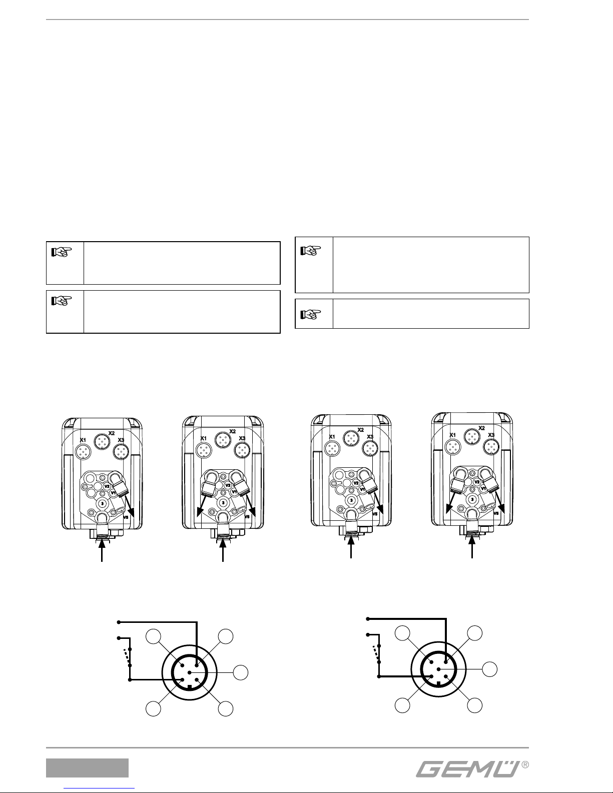
5 Initialisation and
commissioning
The positioner adapts to the valve when
automatic initialisation is started.
All parameters are automatically scanned.
This procedure can take a few minutes,
dependent on the valve.
It may be necessary to close the internal
positioner throttles a little (V1 and V2 for
single acting actuators and V1, V2, V3
and V4 for double acting actuators) if the
actuator volume is very low in order to
increase the valve operating time. This
should only be done during initialisation
in the program step "adjtime".
Experience has shown that valve
operating times of about 1-2
seconds lead to optimal control
results.
The initialisation can alternatively be
started via the parameter "Init Valve".
5.1 Electrical and pneumatic
connection
1. Turn on the pneumatic control air supply
(max. 7 bar) (see chapter 3 "Pneumatic
connections").
Single acting Double acting
2. Switch on the 24V DC power supply
(see chapter 4 "Electrical connections").
GND
+24V DC
43
12
5
X1: Standard
and DeviceNet
X2: Profi Bus DP
Page 13
1436 cPos
®
StartInitValve
3 Sekunden drücken
OK ESC
Init Valve
ESC
OK
13 / 24
Automatische Schnell-Initialisierung
Der Stellungsregler GEMÜ
1436 cPos
®
ist betriebsbereit
und reagiert auf den extern
vorgegebenen Sollwert.
Bei Option "Prozessregler"
muss dieser separat
aktiviert werden (siehe
Betriebsanleitung, Kapitel 15.2).
Ventil kann
auf- und zu
gefahren
werden.
Einschaltmeldung
nach Anlegen der
Versorgungsspannung.
ohne Werksvoreinstellung
= Selbstinitialisierung
3 Sekunden drücken
Diese Meldung
wird 5 Sekunden
lang angezeigt
und erlischt
anschließend
automatisch.
Innerhalb der 5
Sekunden kann mit
der Taste
+
weiter
geschaltet werden.
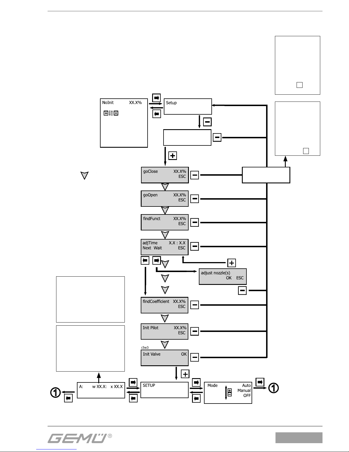
Automatic fast initialisation
Switching message after
connecting the supply
voltage.
Without factory setting
Valve can be
opened and
closed.
Press 3 seconds
This message
is displayed for
five seconds
and then deleted
automatically.
It can be switched
off within the
five seconds by
pressing the
+
key.
The GEMÜ 1436 cPos®
positioner is ready for operation
and reacts to the externally
specifi ed set value.
It must be activated separately
for the "process controller"
option (see operating
instructions, chapter 15.2).
= Automatic
initialisation
Page 14
1436 cPos
®
Diagnosis
1.3
Service
1
ID
255.255.255.255
hrs. XXXXX:XX:XX
I w: XX.X mA
I / O Status
1.1
Gemü specific
1.4
I x: XX.X mA
Relais K1 : K2
Return
1.5
W Proc X
XX.X % XX.X %
Return
Code: 0
Active Level: 3
(0...10000)
Logout?
OK
NewCode:1 0
0...10000
NewCode:2 0
0...10000
Warnings ON
ON...OFF
Login
1.2
V: 1.1 .1.1
min - Pot - max
0,0 % 100 %
Nur verfügba r bei ProcCtr
l
Only available when Proc
C
r0w3
r1w1
r1w1
r2w2
Pos Ctrl Out
Error List
3w0r-w0r
r0
r0w-
w0
In w : x : 1 : 2
ActiveParaSet P1
14 / 24
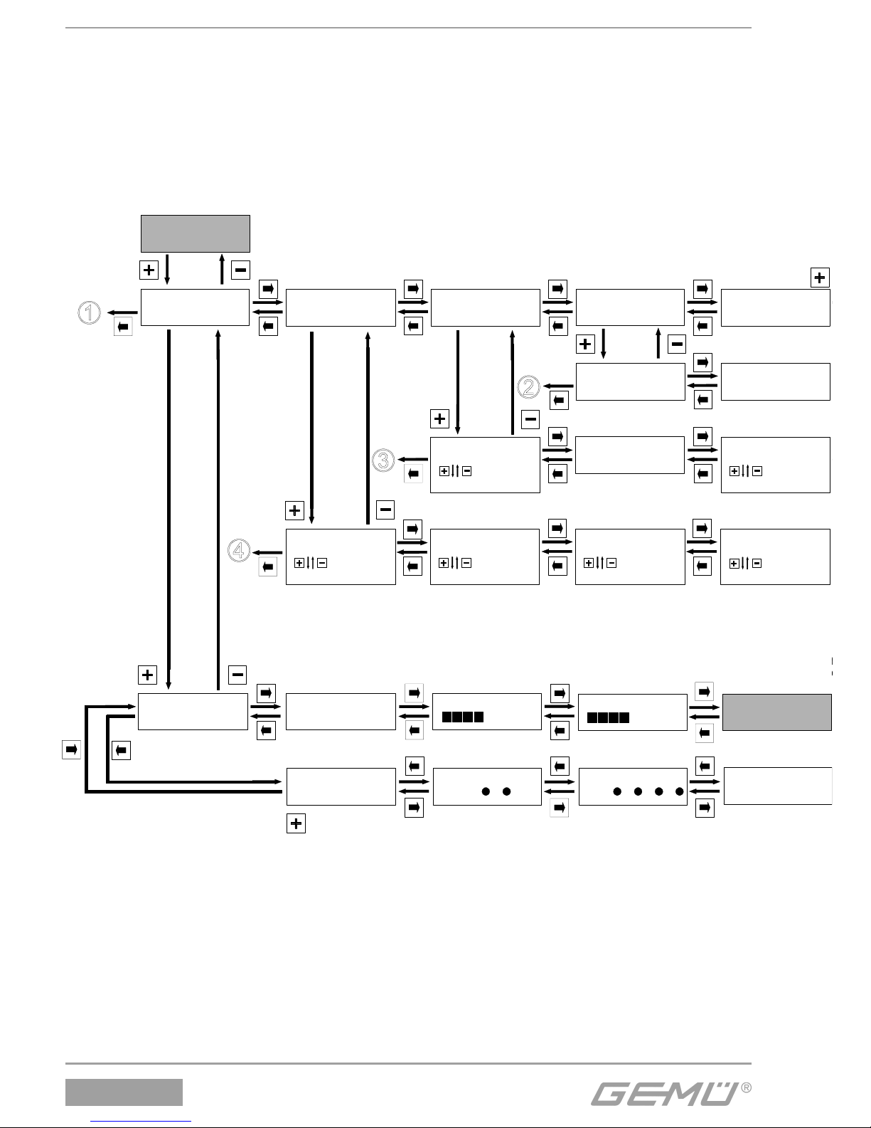
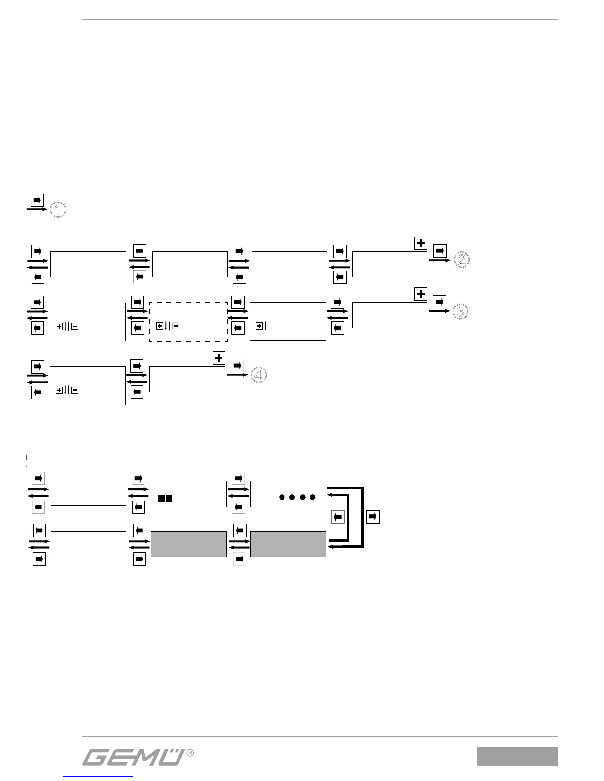
6 Menüstruktur
6.1 Menüstruktur
1. Service
Nur verfügbar bei
ProcCtrlMode: ON
Only available when
ProcCtrlMode: ON
6 Menu structure
6.1 Menu structure
1. Service
Page 15
1436 cPos
®
S/N 743984/ 1
Seriennummer
Return
Proc Ctrl Out
W Pos X
XX.X % XX.X%
Return
Valve 1 : 2 : 3 : 4
Errors ON
ON...OFF
NewCode:3 0
0...10000
Mode: ON
trlMode: ON
Nur verfügbar bei ProcCtrlMode: ON
Only available when ProcCtrlMode: ON
r0w3
r3w3
Pot Abs XX.X %
-w0r
TAG1
TAG1 Nummer
TAG2
TAG2 Nummer
3w0r3w0r
Proc Ctrl In
XX.X %
Pos Ctrl In
XX.X %
Return
r0w3
Clear Error List
OK
r0w3
SensTest Enable 1
Disable
Enable 1
serial number TAG1 number TAG2 number
15 / 24
Nur verfügbar bei ProcCtrlMode: ON
Only available when ProcCtrlMode: ON
Page 16
1436 cPos
®
Return
W-Input: 4-20 mA
0-20 mA
4-20 mA
X-Input: 4-20 mA
0-20 mA
4-20 mA p
Default: Yes
Yes...No
r0w3 r0w3 r3w3
SetBasics
2
Helptext ON
ON...OFF
r0w0
16 / 24
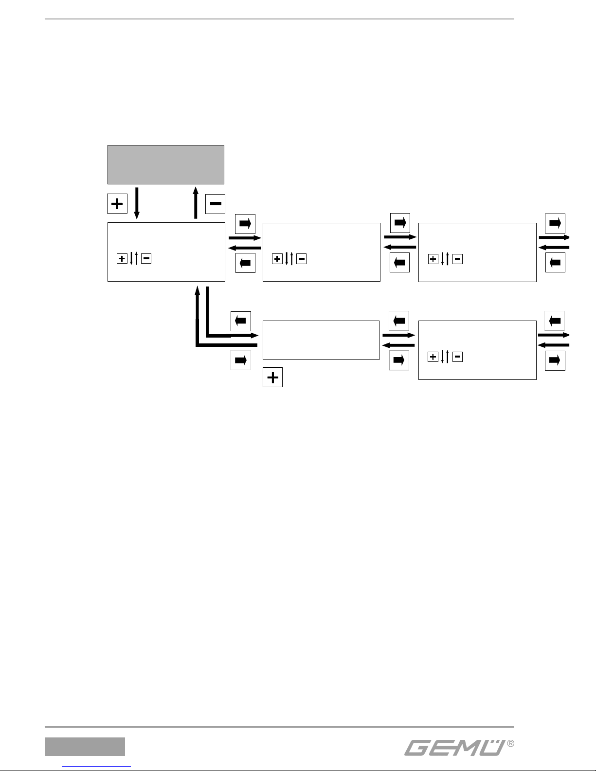
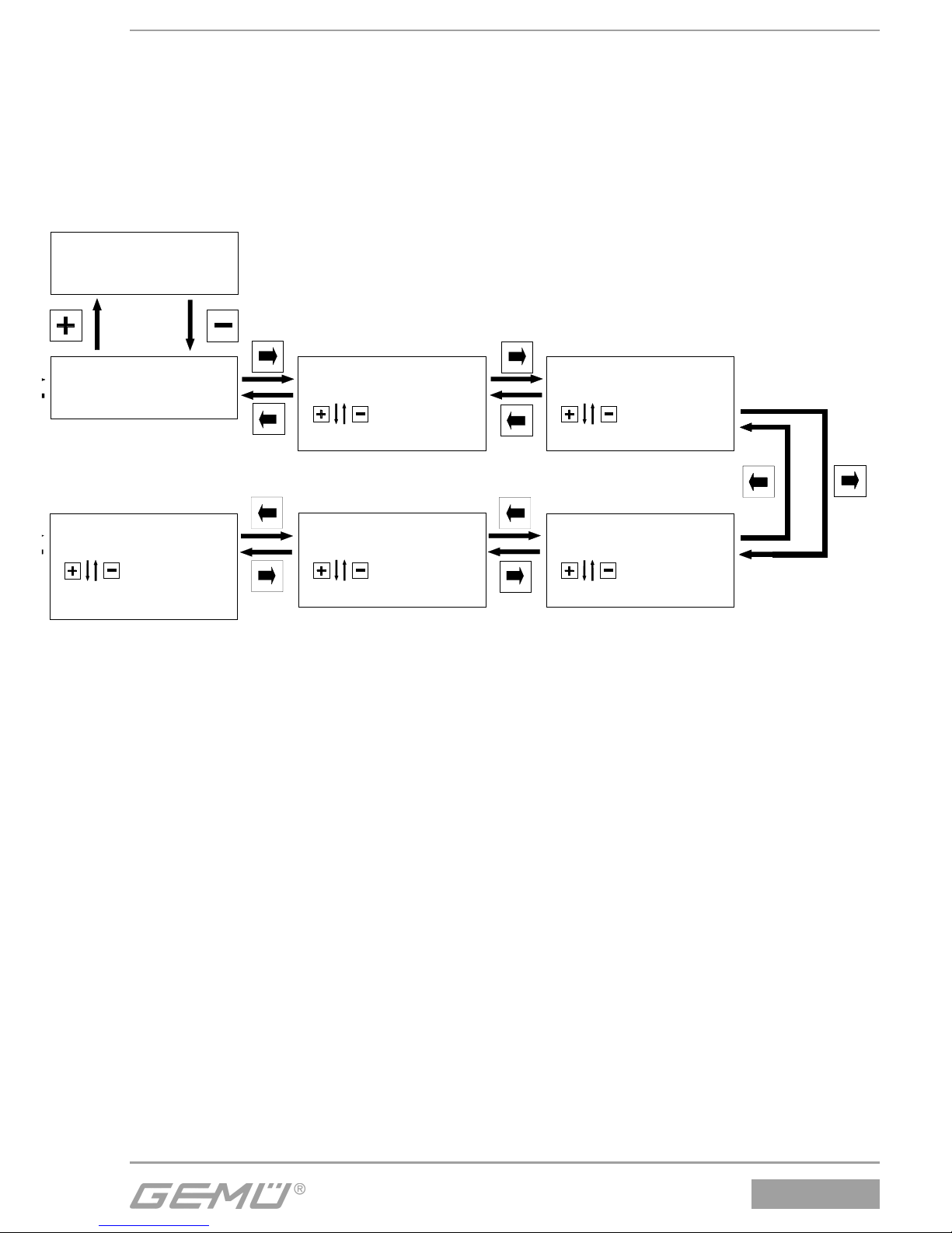
6.2 Menüstruktur
2. SetBasics
6.2 Menu structure
2. SetBasics
Page 17
1436 cPos
®
Init Valve
Init Valve
Auto Man ESC
CalPointQtyt 9
1...19
D. Refresh 0.1 s
0.1...1.0 s
AutoReturn 5min
1...60min
r3w3 r3w3
r0w1
DLight On Key
On Key
On
r0w2
r0w2
HelpLanguage D
D
GB
N
r0w0
17 / 24
Page 18
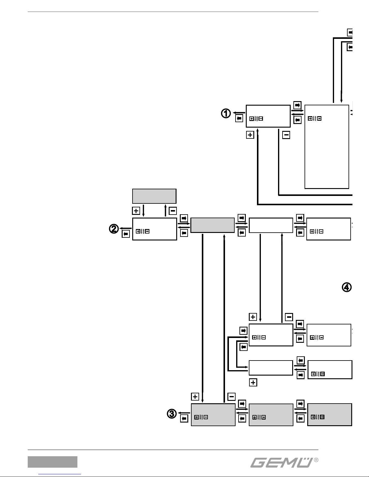
1436 cPos
®
PosCtrl
SetFunction
3
ProcCtrl
Return
Nur verfügbar bei ProcCtrlMode: ON
Only available when ProcCtrlMode: ON
Pos P 1.0
0.0...100.0
Proc-P: 0.50
0.1...100.0
Pos D 1.0
0.0...100.0
Proc-I: 2,0 s
0,1...999,9 s
ProcCtrlMode: OFF
ON...OFF
K1 Fn no
Pmin
Pmax
P min/max
Wmin
Wmax
W min/max
Xmin
X max
Xmin/max
SSE min
SSE max
SSE min/max
Active
Error
Warning
Proc-D: 0.0
0.0...100.0
DeadBand 1.0 %
0.1...25.0 %
OpenTight: 100%
90-100%
r0w3
r0w2
r0w2
r0w3
r0w3
r0w3
r0w3
r0w3
r0w2
K1 Switch NO
NO
NC
r0w1
r0w1
Nur verfügbar bei Reglerausführung
PA01 (mit integriertem Prozessregler)
Only available for positioner design
PA01 (with integrated process controller)
18 / 24
6.3 Menüstruktur
3. SetFunction
Nur verfügbar bei ProcCtrlMode: ON
Nur verfügbar bei Reglerausführung
PA01 (mit integriertem Prozessregler)
6.3 Menu structure
3. SetFunction
Only available when ProcCtrlMode: ON
Only available for positioner design
PA01 (with integrated process
controller)
Page 19
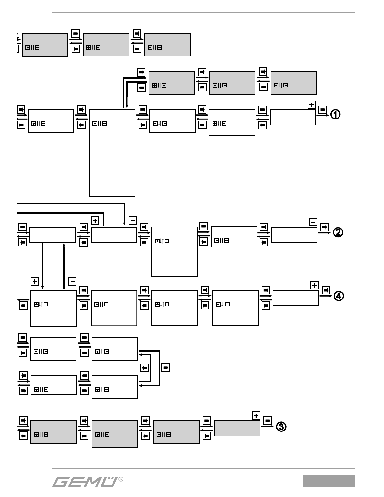
1436 cPos
®
AlarmMinK2 10.0 %
0.2...99.8 %
AlarmMaxK1 10.0 %
0.2...99.8 %
AlarmMinK1 10.0 %
0.2...99.8 %
Proc-T: 1000 ms
1...10000 ms
DigitalOutput
Return
Return
Return
Error Time 0.2 s
0.5...100 s
CpyParaSet OFF
P1<=W
P1=>P2
P1<=P2
P1=>P3
P1<=P3
P1=>P4
P1<=P4
AlarmMaxK2 10.0 %
0.2...99.8 %
Pos T 100 ms
1...5000 ms
MinPos 0.0 %
0.0...100.0 %
MaxPos 100.0 %
0.0...100.0 %
Nur verfügbar wenn K1/K2 Func dies erfordert.
Only available when required by K1/K2 function.
r3w3
r0w2
r0w1
r0w1
r0w1
r0w1
r0w1
r0w3
r0w3
r0w3
CloseTight: 0%
0...10%
K2 Switch NO
NO
NC
Error Action close
close
open
hold
Nur verfügbar wenn K1/K2 Func dies erfordert.
Only available when required by K1/K2 function.
r0w1
r0w1
r0w1
Nur verfügbar wenn Proc D > 0
Only available when Proc D > 0
K2 Fn no
Pmin
P max
P min/max
Wmin
W max
W min/max
Xmin
Xmax
Xmin/max
Active
Error
Warning
SSE min
SSE max
SSE min/max
r0w3
r0w3
DigitalInput
Return
In W OFF
OFF / ON
safe / ON
ParmSetB0
ParmSetB1
Poti / Ix
r0w3
r0w3
r0w3
In X OFF
OFF / ON
safe/ON
ParmSetB0
ParmSetB1
Poti / Ix
In 1 OFF
OFF / ON
safe/ON
ParmSetB0
ParmSetB1
Poti / Ix
In 2 OFF
OFF / ON
safe / ON
ParmSetB0
ParmSetB1
Poti / Ix
IxTime 0.10 s
0.10...20.00 s
r0w3
IxType OFF
OFF
RC
avr
r0w3
r3w3
AnalogOut Poti
Poti
Ix
R0w
SSE1Time 5.0 s
0.1...100.0 s
R0w
SSE2Time 5.0 s
0.1...100.0 s
r0w3
19 / 24
Nur verfügbar wenn K1/K2 Func dies erfordert.
Nur verfügbar wenn K1/K2 Func dies erfordert.
Nur verfügbar wenn Proc D > 0
Only available when required by K1/K2 function.
Only available when required by K1/K2 function.
Only available when Proc D > 0
Page 20
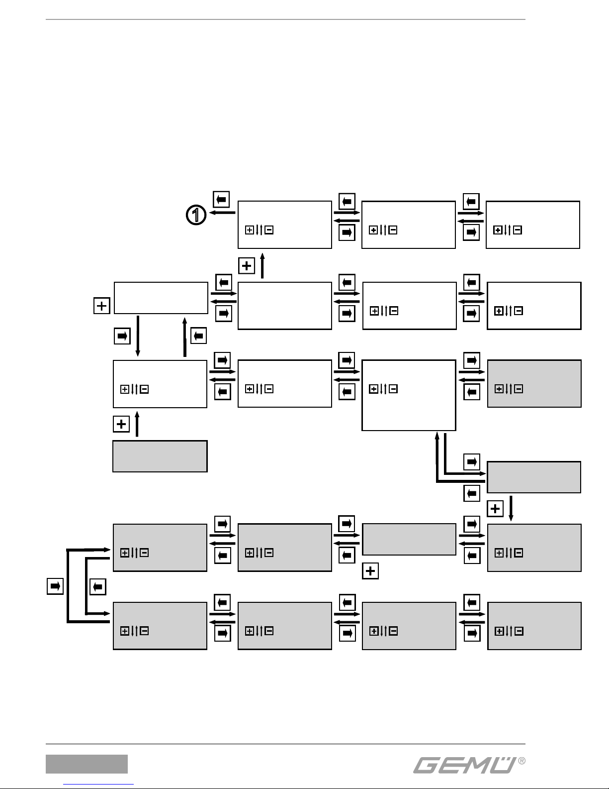
1436 cPos
®
W0% 0.0%
0.0...100.0 %
SetCalibration
4
Return
Return
Set W-free
X-Direction: rise
rise...fall
W-Direction: rise
rise...fall
W 90% 90.0 %
0.0...100.0 %
W 70% 70.0 %
0.0...100.0 %
W 50% 50.0 %
0.0...100.0 %
W 100% 100.0 %
0.0...100.0 %
W 80% 80.0 %
0.0...100.0 %
W 60% 60.0 %
0.0...100.0 %
W-Function: lin.
lin.
1:25
1:50
free
Nur verfügbar wenn W-Funktion: free
Only available when W-Funktion: free
r0w3
r0w3 r0w3
r0w3
r0w3
r0w3
r0w3
r0w3r0w3
r0w3 r0w3
IMinX 3.5mA
0.0...22.0 mA
r3w3
I Max X 20.5 mA
0.0...22.0 mA
r3w3
Decimalpoint 1
0...2
Scaling
4mA = 0%
0.0...9999
r0w3r0w3
r0w3
Scaling OFF
ON / OFF
r0w3
Y-Direction: rise
rise...fall
r0w3
20 / 24
6.4 Menüstruktur
4. SetCalibration
Nur verfügbar bei ProcCtrlMode: ON
Nur verfügbar wenn W-Funktion: free
6.4 Menu structure
4. SetCalibration
Only available when ProcCtrlMod
Only available when W-Function: free
Page 21
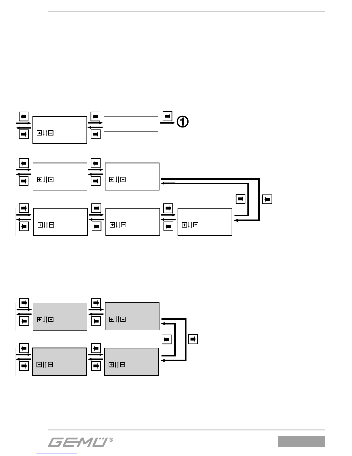
1436 cPos
®
OutMinPos 0.0 %
0.0...100.0 %
W 10% 10.0 %
0.0...100.0 %
W 40% 40.0 %
0.0...100.0 %
W 20% 20.0 %
0.0...100.0 %
W 30% 30.0 %
0.0...100.0 %
OutMaxPos 100.0 %
0.0...100.0 %
r0w3
r0w3
r0w3r0w3
r0w2 r0w2
PotiDir rise
rise
fall
r0w3
I Max W 20.5 mA
0.0...22.0 mA
IMinW 3.5mA
0.0...22.0 mA
r3w3 r3w3
Return
20mA = 100.0 %
0.0...9999
r0w3
r0w3
21 / 24
e: ON
Page 22
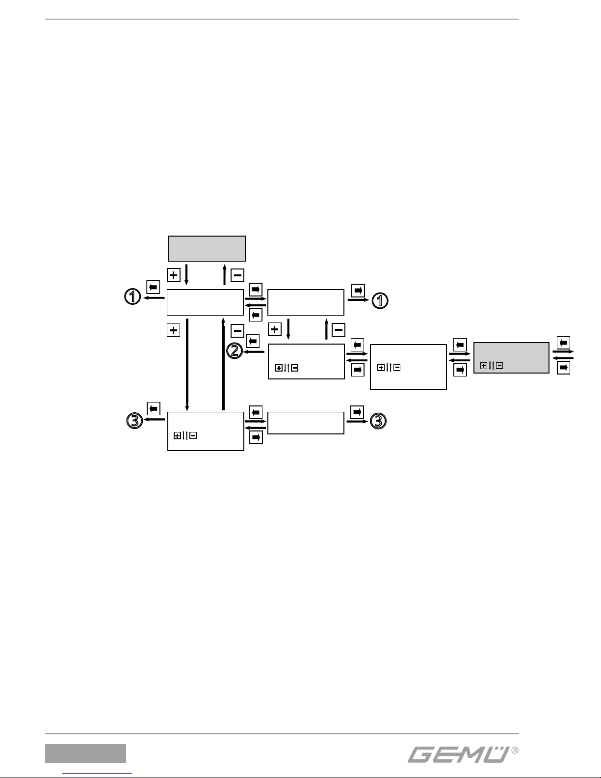
1436 cPos
®
Communication
5
WebServer
5.2
r0w3
RS 232 Auto
Auto
Serial
Fieldbus
5.1
Return
r0w3
Fieldbus OFF
ON / OFF
Bdrate RS 115200
38400
57600
115200
r0w3
ComPort
Bluetooth
Bluetooth
22 / 24
6.5 Menüstruktur
5. Communication
6.5 Menu structure
5. Communication
Page 23
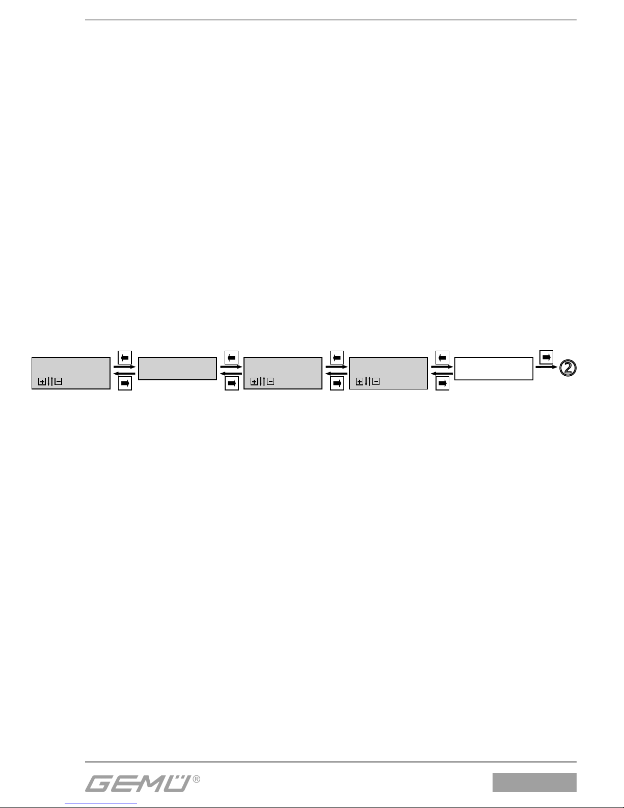
1436 cPos
®
ReturnBT Code 0000
0000...9999
BT Name
1436 cPos
StateBT Function PC/PDA
PC/PDA
Phone
Nur verfügbar bei Regler-Ausführung mit integrierter Bluetooth-Schnittstelle
23 / 24
Nur verfügbar bei Reglerausführung mit integrierter Bluetooth-Schnittstelle
Only available for positioner version with integrated bluetooth interface
Page 24
Hinweis:
Handhabung, Montage und
Inbetriebnahme, sowie Einstellund Justierarbeiten, dürfen nur
von autorisiertem Fachpersonal
durchgeführt werden. Für Schäden,
welche durch unsachgemäße
Handhabung oder Fremdeinwirkung
entstehen, übernimmt GEMÜ
keinerlei Haftung. Nehmen Sie im
Zweifelsfall vor Inbetriebnahme
Kontakt mit GEMÜ auf.
Hinweis zur Mitarbeiterschulung:
Zur Mitarbeiterschulung nehmen
Sie bitte über die Adresse auf der
letzten Seite Kontakt auf.
Im Zweifelsfall oder bei Missverständnissen
ist die deutsche Version des Dokuments
ausschlaggebend!
Note:
Handling, assembly and
commissioning, in addition to
setting and adjustment must be
performed only by authorised
trained personnel.GEMÜ shall
assume no liability whatsoever
for damages caused by improper
handling or third-party actions. In
case of doubt contact GEMÜ before
commissioning.
Note on staff training:
Please contact us at the address
on the last page for staff training
information.
Should there be any doubts or
misunderstandings in the preceding text,
the German version of this document is the
authoritative document!
GEMÜ Gebr. Müller Apparatebau GmbH & Co. KG · Fritz-Müller-Str. 6-8 · D-74653 Ingelfi ngen-Criesbach
Telefon +49(0)7940/123-0 · Telefax +49(0)7940/123-192 · [email protected] · www.gemu-group.com
Änderungen vorbehalten · Subject to alteration · 02/2016 · 88250588
 Loading...