

Page 1
1234
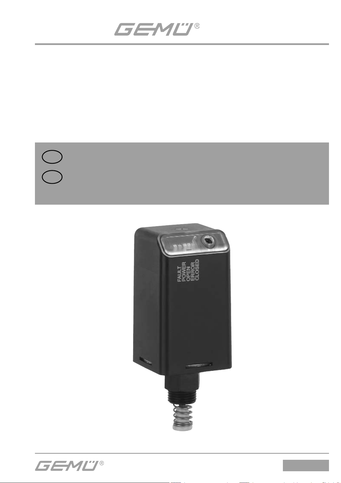
Elektrischer Stellungsrückmelder
programmierbar
Electrical position indicator
programmable
DE
GB
ORIGINAL EINBAU- UND MONTAGEANLEITUNG
INSTALLATION, OPERATING AND
MAINTENANCE INSTRUCTIONS
1234
Page 2

Inhaltsverzeichnis
1 Hinweise zu Ihrer Sicherheit 3
1.1 Allgemeines 3
1.2 Symbol- und Hinweiserklärung 3
1.3 Sicherheitshinweise 4
1.4 Hinweise für den Einsatz in feuchter Umgebung 4
2 Funktion 4
2.1 24 V Version 5
2.2 AS-Interface Version 5
3 Bestimmungsgemäßer Gebrauch 6
4 Herstellerangaben 6
4.1 Lieferung und Leistung 6
4.2 Lagerung 6
4.3 Benötigtes Werkzeug 6
5 Montage / Demontage 7
5.1 Montage Anbausatz 7
5.2 Montage elektrischer Stellungsrückmelder 7
5.3 Demontage 8
6 Elektrische Anschlüsse 8
6.1 24 V Version 8
6.2 AS-Interface Version 8
7 Programmierung der Endlagen 9
7.1 24 V Version 9
7.2 AS-Interface Version 10
8 Schaltpunkteinstellung 10
8.1 24 V Version 11
8.2 AS-Interface Version 13
9 Maße 13
10 Technische Daten 14
11 Bestelldaten 16
12 Zubehör 16
13 Entsorgung 17
14 Rücksendung 17
15 Hinweise 17
16 EG-Konformitätserklärung 18
1234
2 / 36
Page 3

1 Hinweise zu Ihrer Sicherheit
Nachfolgende Hinweise sorgfältig durchlesen und beachten!
Der Hersteller übernimmt für den elektrischen Stellungsrückmelder GEMÜ 1234 keine
Verantwortung, wenn diese Sicherheitshinweise nicht beachtet werden.
1.1 Allgemeines
Voraussetzungen für eine einwandfreie Funktion des elektrischen Stellungsrückmelders
GEMÜ 1234:
• Sachgerechter Transport und Lagerung
• Installation und Inbetriebnahme durch eingewiesenes Fachpersonal
• Bedienung gemäß dieser Einbau- und Montageanleitung
• Ordnungsgemäße Instandhaltung
Der elektrische Stellungsrückmelder GEMÜ 1234 ist vom Betreiber
bestimmungsgemäß zu gebrauchen. Alle Angaben dieser Einbau- und
Montageanleitung in Hinsicht auf Betrieb, Wartung und Instandhaltung sind
zu beachten und anzuwenden. Bei Nichtbeachten dieser Angaben erlischt der
Garantieanspruch des Betreibers sowie die gesetzliche Haftung des Herstellers.
Beachten Sie deshalb:
• Den Inhalt dieser Einbau- und Montageanleitung
• Die einschlägigen Sicherheitsvorschriften für die Errichtung und den Betrieb elektrischer
Anlagen
• Dass dieses Gerät nicht im explosionsgefährdeten Bereich eingesetzt werden darf.
Die in dieser Einbau- und Montageanleitung genannten Verordnungen, Normen und
Richtlinien gelten nur für Deutschland. Bei Einsatz des elektrischen Stellungsrückmelders
GEMÜ 1234 in anderen Ländern sind die dort geltenden nationalen Regeln zu beachten.
Wenn es sich um harmonisierte europäische Normen, Standards und Richtlinien handelt,
gelten diese im EG-Binnenmarkt. Für den Betreiber können zusätzlich nationale Richtlinien
und Vorschriften gelten.
Die Beschreibungen und Instruktionen in dieser Sicherheitsanweisung beziehen sich auf die
Standardausführung.
Die Sicherheitshinweise berücksichtigen nicht
• Zufälligkeiten und Ereignisse, die bei Montage, Betrieb und Wartung auftreten können.
• Die ortsbezogenen Sicherheitsbestimmungen, für deren Einhaltung - auch seitens des
hinzugezogenen Montagepersonals - der Betreiber verantwortlich ist.
Bei Rückfragen wenden Sie sich bitte an die nächstgelegene GEMÜ-Verkaufsniederlassung.
1.2 Symbol- und Hinweiserklärung
Folgende Symbole kennzeichnen wichtige Informationen in dieser Einbau- und
Montageanleitung:
VORSICHT
Möglicherweise gefährliche Situation!
® Bei Nichtbeachtung drohen Sachschäden.
3 / 36
1234
Page 4

1.3 Sicherheitshinweise
Die in diesen Sicherheitshinweisen aufgeführten Punkte, die bestehenden nationalen
und europäischen Vorschriften zur Unfallverhütung sowie eventuelle interne Arbeits-,
Betriebs- und Sicherheitsvorschriften des Betreibers beachten. Nur qualifiziertes und
eingewiesenes Fachpersonal darf den elektrischen Stellungsrückmelder GEMÜ 1234
montieren, elektrisch anschließen und in Betrieb nehmen. Das Personal für Bedienung,
Wartung, Inspektion und Montage muss die entsprechende Qualifikation für diese Arbeiten
aufweisen. Verantwortungsbereich, Zuständigkeit und die Überwachung des Personals
muss durch den Betreiber genau geregelt sein. Liegen beim Personal nicht die notwendigen
Kenntnisse vor, so ist dieses zu schulen und zu unterweisen. Dies kann, falls erforderlich,
im Auftrag des Betreibers durch den Hersteller / Lieferer erfolgen. Weiterhin ist durch den
Betreiber sicherzustellen, dass der Inhalt der Sicherheitsanweisung durch das Personal voll
verstanden wird. Stellen Sie unbedingt die elektrische Sicherheit der speisenden Geräte
sicher. Beachten Sie auch die Einhaltung der elektrischen Daten.
Die Nichtbeachtung der Sicherheitshinweise kann sowohl eine Gefährdung für Personen
als auch für die Umwelt und den elektrischen Stellungsrückmelder GEMÜ 1234 zur
Folge haben. Die Nichtbeachtung der Sicherheitshinweise kann zum Verlust jeglicher
Schadensersatzansprüche führen.
Gesetzliche Bestimmungen einhalten.
1.4 Hinweise für den Einsatz in feuchter Umgebung
Folgende Informationen geben Hilfestellung bei Montage und Betrieb des elektrischen
Stellungsrückmelders GEMÜ 1234 in feuchter Umgebung.
• Kabel und Rohre so verlegen, dass Kondensat oder Regenwasser, das an Rohren /
Leitungen hängt, nicht in Kabelverschraubungen des elektrischen Stellungsrückmelders
GEMÜ 1234 laufen kann
• Alle Kabelverschraubungen auf festen Sitz prüfen
VORSICHT
Elektrischen Stellungsrückmelder unter keinen Umständen mit Hochdruckreiniger
reinigen, Schutzart beachten!
2 Funktion
Der elektrische Stellungsrückmelder GEMÜ 1234 arbeitet mit einer
mikroprozessorgesteuerten, intelligenten Stellungserfassung sowie einem analogen,
integrierten Wegmesssystem. Der Hub wird mit einem Potentiometer erfasst, dessen
Spindel mit Hilfe eines Anbausatzes (Feder, Betätigungsspindel) kraftschlüssig mit der
Spindel des Antriebs verbunden ist. Die elektrische Stellungsrückmeldung erfolgt durch
24 V DC Signale (24 V Version) oder über AS-Interface.
Zusätzlich zur elektrischen Stellungsrückmeldung erfolgt eine optische Signalisierung
mittels LEDs, die von oben und von vorne sichtbar sind.
1234
4 / 36
Page 5
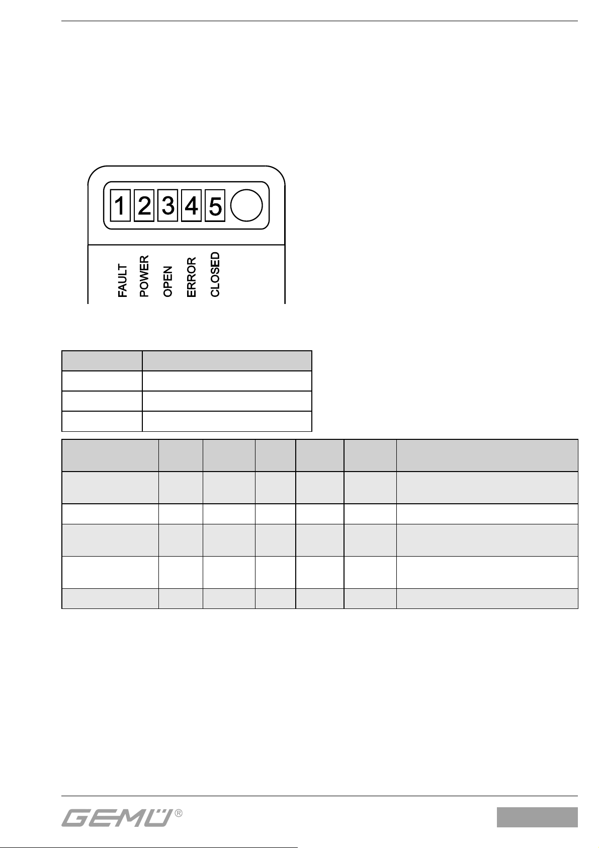
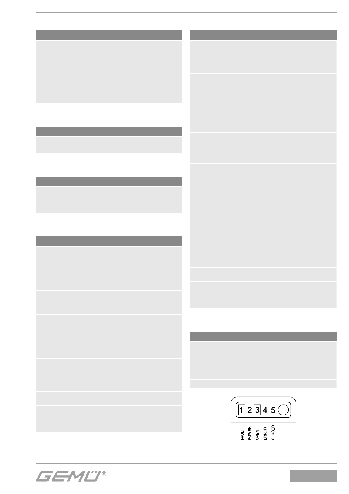
Es werden folgende Funktionen optisch angezeigt:
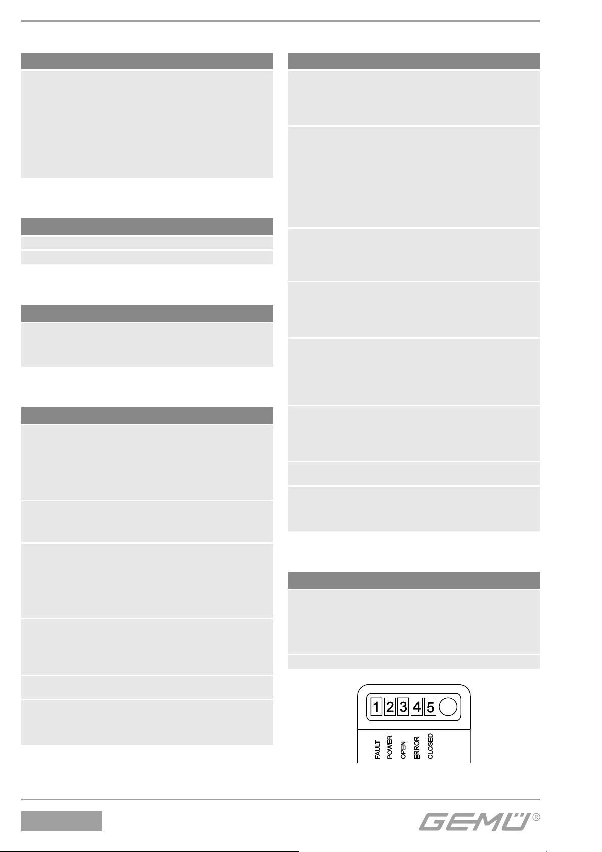
• FAULT → LED1 rot
• POWER → LED2 grün / gelb
• OPEN → LED3 gelb
• ERROR → LED4 rot
• CLOSED → LED5 orange
• Programmiermodus (siehe Kapitel 7 "Programmierung der Endlagen")
• Schaltpunkteinstellung (siehe Kapitel 8 "Schaltpunkteinstellung")
Folgende Fehlermeldungen werden außerdem über LEDs signalisiert:
Legende LED Zustand
X LED leuchtet
O LED blinkt
- LED aus
Fehlerursache
Tasterfehler O X - O -
Programmierfehler - X - X O Neu programmieren
Sensorfehler O X O X -
Speicherfehler O X O X O
AS-Interface Fehler X X - - - *Anzeige nur bei AS-Interface aktiv
LED 1*
FAULT
LED 2
POWER
LED 3
OPEN
LED 4
ERROR
LED 5
CLOSED
Fehlerbeseitigung
Taster loslassen
(Taster wurde länger als 4 s betätigt)
Sensorgrenze überfahren.
Hub ≤ 10 mm gewährleisten
Neu programmieren.
Erneut Fehler = defekt
2.1 24 V Version
Die Spannungsversorgung sowie die AUF/ZU-Rückmeldungen erfolgen über 24 V DC
(Schaltcharakteristik siehe Kapitel 10 "Technische Daten").
2.2 AS-Interface Version
Die Spannungsversorgung sowie die AUF/ZU-Rückmeldungen erfolgen über AS-Interface
(Schaltcharakteristik siehe Kapitel 10 "Technische Daten").
5 / 36
1234
Page 6

3 Bestimmungsgemäßer Gebrauch
Der elektrische Stellungsrückmelder GEMÜ 1234 ist für den Einsatz entsprechend dem
Datenblatt geeignet.
Um eine einwandfreie Funktion unserer Produkte zu erlangen sind die im folgenden
aufgeführten Hinweise zu beachten. Zusätzlich sind die Angaben auf den Typenschildern zu
beachten.
Wenn diese Hinweise als auch die Hinweise in der allgemeinen Einbau- und
Montageanleitung nicht beachtet werden erlischt die Garantie auf den elektrischen
Stellungsrückmelder GEMÜ 1234 sowie die gesetzliche Haftung.
Der elektrische Stellungsrückmelder GEMÜ 1234 dient ausschließlich als Messgerät zur
elektrischen und optischen Stellungserfassung für Linearantriebe mit einem Maximalhub
von 10 mm (siehe Kapitel 10 "Technische Daten") und ist laut Datenblatt einzusetzen. Eine
andere oder darüber hinausgehende Benutzung gilt als nicht bestimmungsgemäß. Für
hieraus resultierende Schäden haftet GEMÜ nicht. Das Risiko trägt allein der Anwender.
Bitte beachten Sie bei der Planung des Einsatzes als auch des Betreibens des Gerätes die
einschlägigen allgemein anerkannten Sicherheitstechnischen Regeln. Für Positionierung
und Einbau des elektrischen Stellungsrückmelders GEMÜ 1234 ist grundsätzlich Planer,
Anlagenbauer bzw. Betreiber verantwortlich.
4 Herstellerangaben
4.1 Lieferung und Leistung
Überprüfen Sie die Ware unverzüglich bei Erhalt auf Vollständigkeit und Unversehrtheit.
Aus den Versandpapieren geht der Lieferumfang hervor.
Stellen Sie anhand der Bestellnummern fest, ob die Ware hinsichtlich der Ausführung und
des Umfangs bestellgemäß geliefert wurde. Wird der Stellungsrückmelder GEMÜ 1234
mit einem Ventil als Kompletteinheit bestellt, so sind diese Teile sowie das dazugehörige
Zubehör bereits komplett montiert und werkseitig voreingestellt.
Der GEMÜ Stellungsrückmelder ist damit betriebsbereit.
4.2 Lagerung
Elektrischen Stellungsrückmelder trocken in Originalverpackung lagern. UV-Strahlung und
direkte Sonneneinstrahlung vermeiden. Maximale Lagertemperatur 70 °C.
4.3 Benötigtes Werkzeug
Benötigtes Werkzeug für Einbau und Montage ist nicht im Lieferumfang enthalten!
Passendes, funktionsfähiges und sicheres Werkzeug benutzen!
1234
6 / 36
Page 7
5 Montage / Demontage
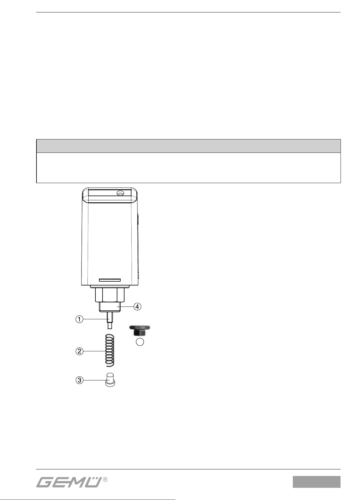
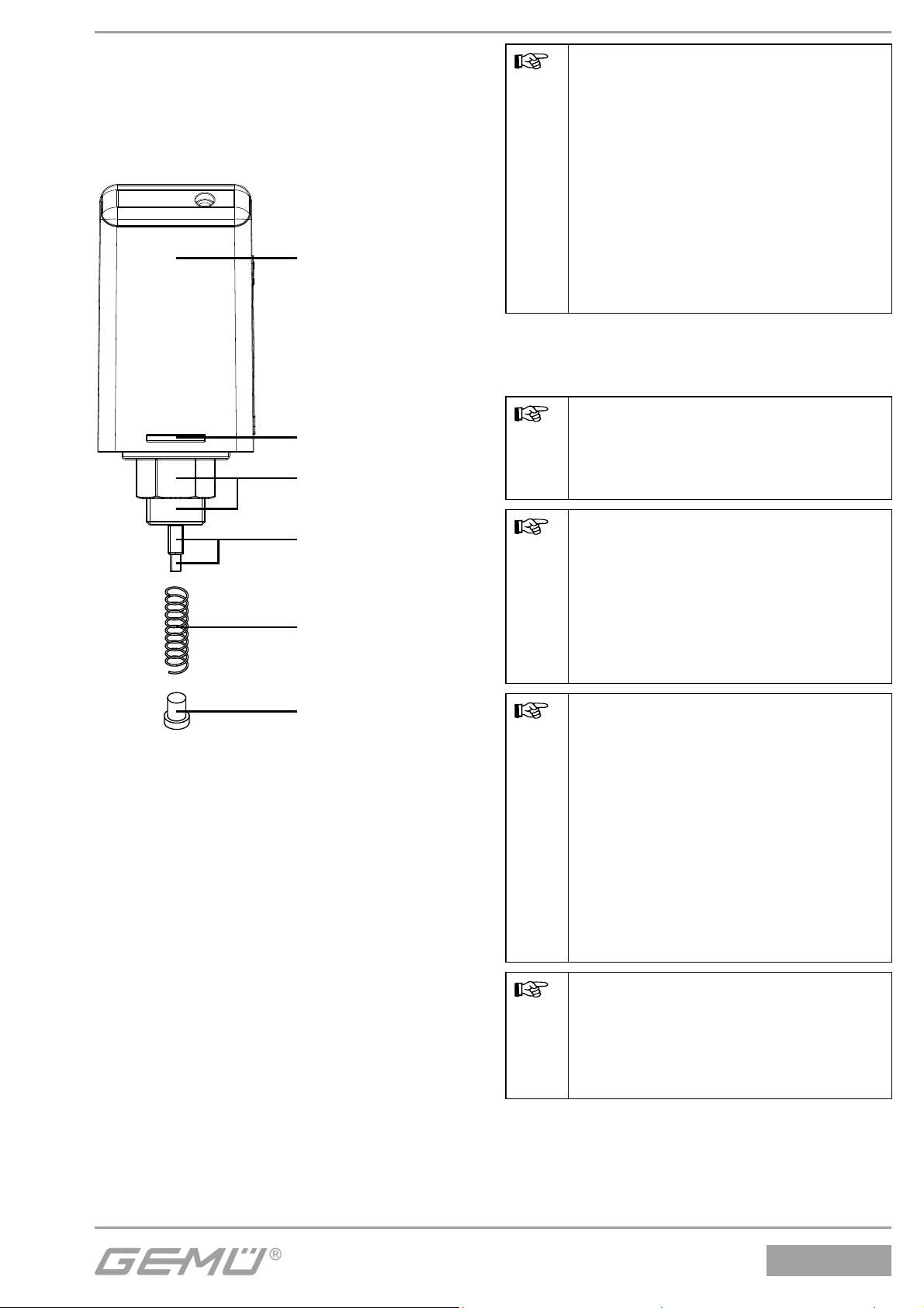
5.1 Montage Anbausatz
GEMÜ 1234 S01Z ... Anbausätze enthalten eine Feder 2, eine Betätigungsspindel 3 und je
nach Ausführung einen Gewindeadapter 5.
Bei der Montage folgendermaßen vorgehen:
• Spindel 1 herausziehen
• Feder 2 über die Spindel 1 schieben
• Betätigungsspindel 3 auf das Gewinde der Spindel 1 aufschrauben
• Gewindeadapter 5 auf M12x1 Gewinde 4 aufschrauben (nur wenn Gewindeadapter 5
beiliegt)
VORSICHT
• Weggeber nicht schlagartig entlasten!
• Spindel nicht verkratzen!
• Gewinde der Betätigungsspindel nicht überdrehen!
5
5.2 Montage elektrischer Stellungsrückmelder
Bei nachträglicher Montage auf ein Prozessventil muss wie folgt vorgegangen werden:
• Mechanische Stellungsanzeige entfernen (falls vorhanden)
• Verschlussstopfen entfernen (falls vorhanden)
• Stellungsrückmelder mit Anbausatz in Ventil einschrauben
7 / 36
1234
Page 8
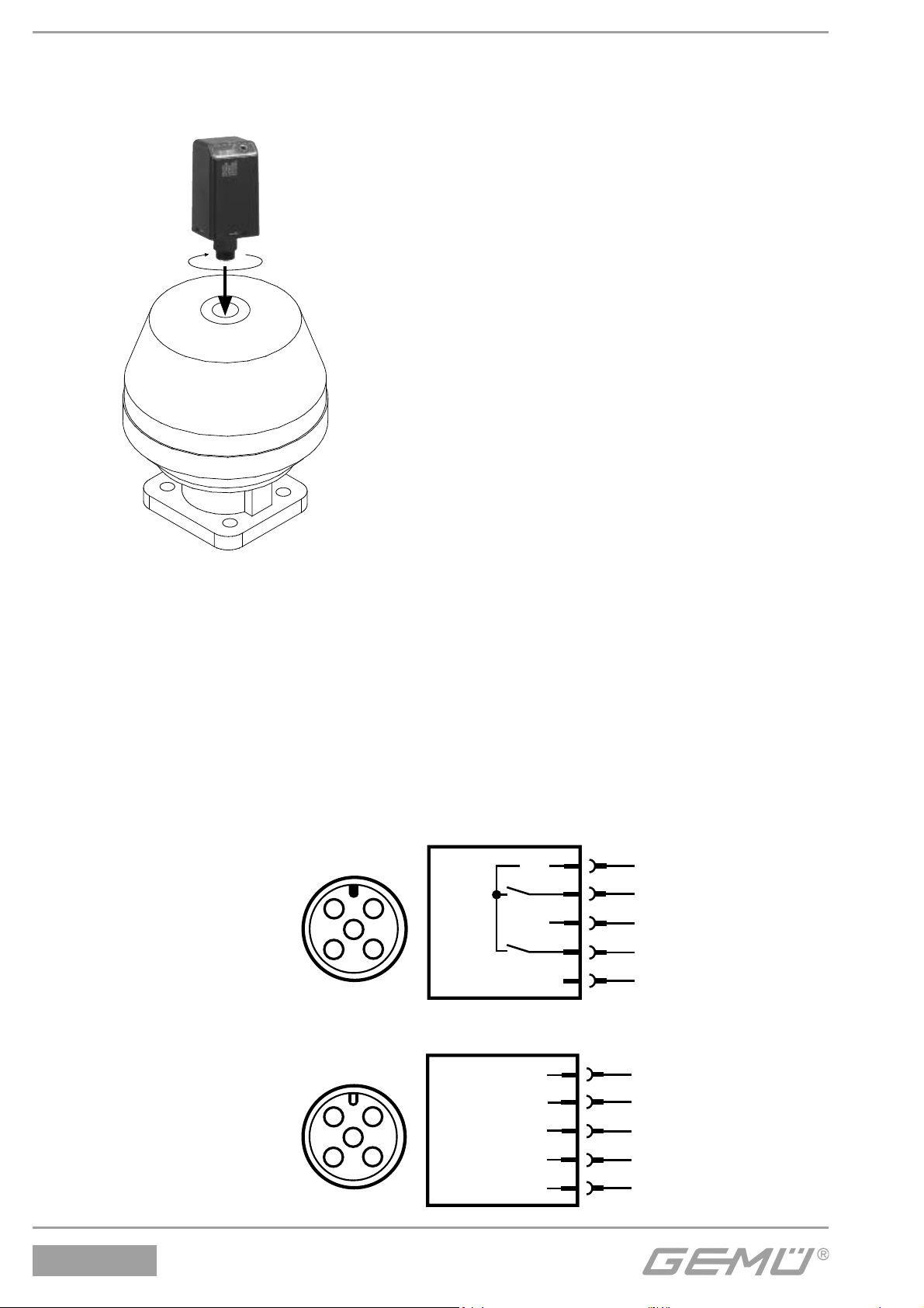
• Am Sechskant SW 27 mit max. 4 Nm festziehen
• Externe Kabeldose leicht andrücken (nicht verkanten) und anschrauben
• Anschlussspannung anlegen (siehe Kapitel 6 "Elektrische Anschlüsse")
5.3 Demontage
Die Demontage des Anbausatzes / des elektrischen Stellungsrückmelders in der
umgekehrten Reihenfolge wie die Montage in Kapitel 5.1 - 5.2 durchführen.
6 Elektrische Anschlüsse
6.1 24 V Version
GEMÜ 1234
mit 5-poligem M12
Anschlussstecker
U+
2
1
5
3
4
0 V
1
Uv, 24 V DC
2
Signal "AUF"
3
Uv, GND
4
Signal "ZU"
5
Programmiereingang
6.2 AS-Interface Version
GEMÜ 1234
AS-Interface
mit 5-poligem M12
Anschlussstecker
AS-i +
2
1
5
4
3
AS-i -
1
3
AS-i +
AS-i -
1234
AS-Interface
8 / 36
Page 9
7 Programmierung der Endlagen
Bei werkseitig vormontierten Stellungsrückmeldern an das Prozessventil ist die
Endlagenrückmeldung bereits programmiert.
VORSICHT
• Bei nachträglichem Anbau des Antriebs an den Ventilkörper sowie bei Nachziehen /
Austauschen der Absperrmembrane ist eine Neuprogrammierung der Endlagen nötig
• Bei Einsatz einer Hubbegrenzung auf den erforderlichen Mindesthub achten (siehe
Kapitel 10 "Technische Daten")
• Der Weggeber des GEMÜ 1234 benötigt immer eine geringe Vorspannung, d.h. die
Spindel muss immer leicht betätigt sein (siehe Kapitel 10 "Technische Daten")
7.1 24 V Version
Die Endlagen können manuell vor Ort oder extern über einen Programmiereingang (Pin5)
programmiert werden.
Manuelle Programmierung
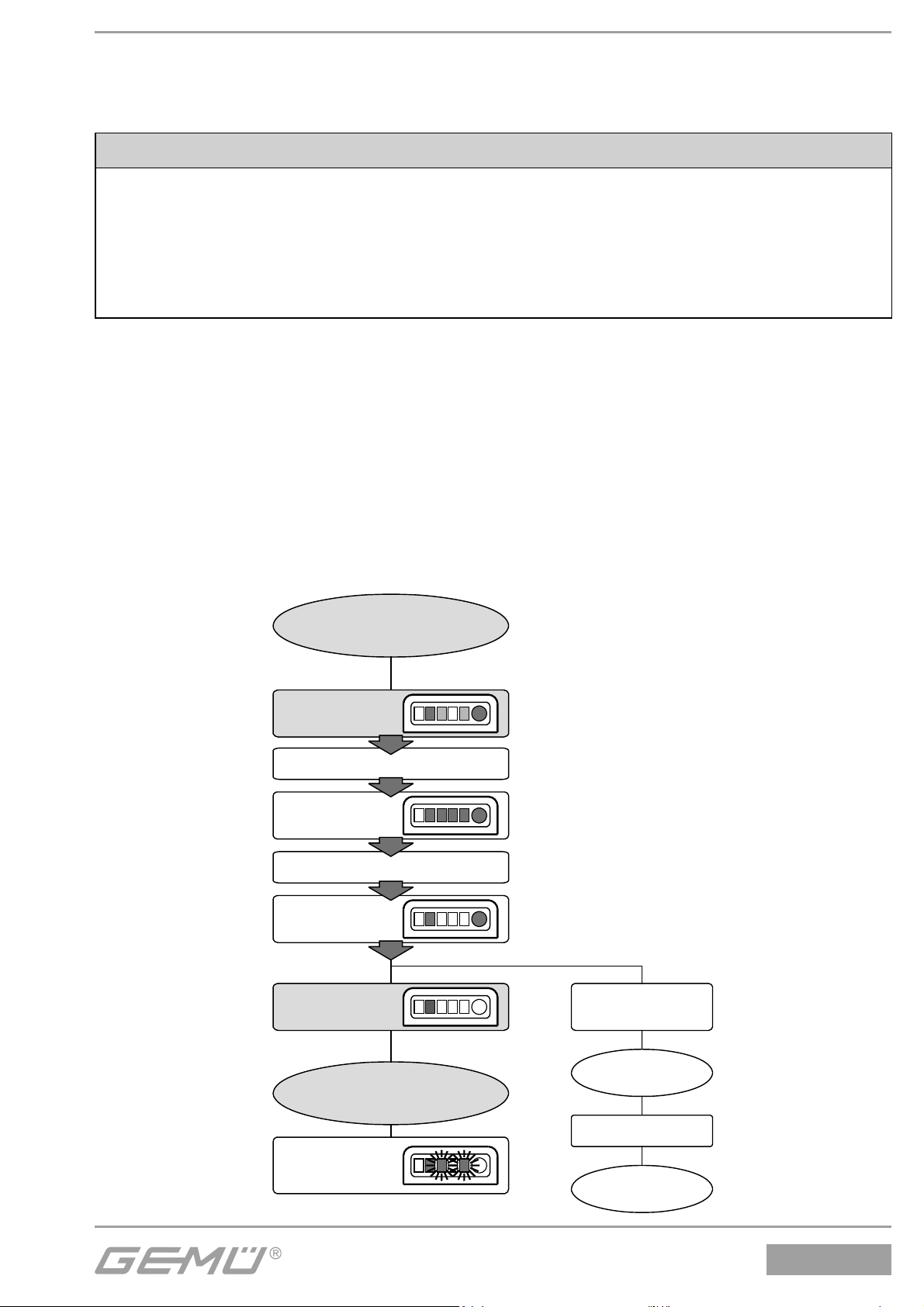
Bei manueller Programmierung wird mittels des Tasters der Programmiermodus
eingeschaltet. Das Programmierende wird automatisch erkannt und in Normalbetrieb
geschaltet.
Zur manuellen Programmierung der Endlagen folgendermaßen vorgehen:
• Elektrischen Stellungsrückmelder in Programmiermodus setzen:
Normalbetrieb
Taster betätigen u. halten
0,5 sec.
LEDs 3, 4, 5
leuchten
3 sec.
LEDs 3, 4, 5
aus
Taster
loslassen
Taster weiter
betätigt (>2 sec.)
Programmiermodus
LEDs 3 und 5
blinken
alternierend
9 / 36
Tasterfehler
Taster loslassen
Normalbetrieb
1234
Page 10
• Ventil auffahren, bis Endlage erreicht ist
• Ventil zufahren, bis Endlage erreicht ist
• Endlagen sind eingestellt
Externe Programmierung
Bei externer Programmierung wird über einen Programmiereingang (Pin5) der
Programmiermodus eingeschaltet. Das Programmierende wird automatisch erkannt und in
Normalbetrieb geschaltet.
Zur externen Programmierung der Endlagen folgendermaßen vorgehen:
• Versorgungsspannung 24 V DC (Pin1), GND (Pin3) anschließen
• Kurzes Signal (24 V DC) auf Pin5 (Programmiereingang)
• LED gelb leuchtet und die LEDs orange und grün blinken alternierend
• Ventil auffahren, bis Endlage erreicht ist
• Ventil zufahren, bis Endlage erreicht ist
• Endlagen sind eingestellt
7.2 AS-Interface Version
Bei der AS-Interface Version besteht zusätzlich zur Vorortprogrammierung (siehe Kapitel 7.1
"24 V Version" / Manuelle Programmierung) noch die Möglichkeit, die Endlagen über ASInterface zu programmieren.
Zur Programmierung über AS-Interface folgendermaßen vorgehen:
• DO2 = 1 setzen (Stellungsrückmelder in Programmiermodus)
• Ventil auffahren, bis Endlage erreicht ist
• Ventil zufahren, bis Endlage erreicht ist
• DO2 = 0 setzen (Stellungsrückmelder in Normalbetrieb)
• Endlagen sind eingestellt
8 Schaltpunkteinstellung
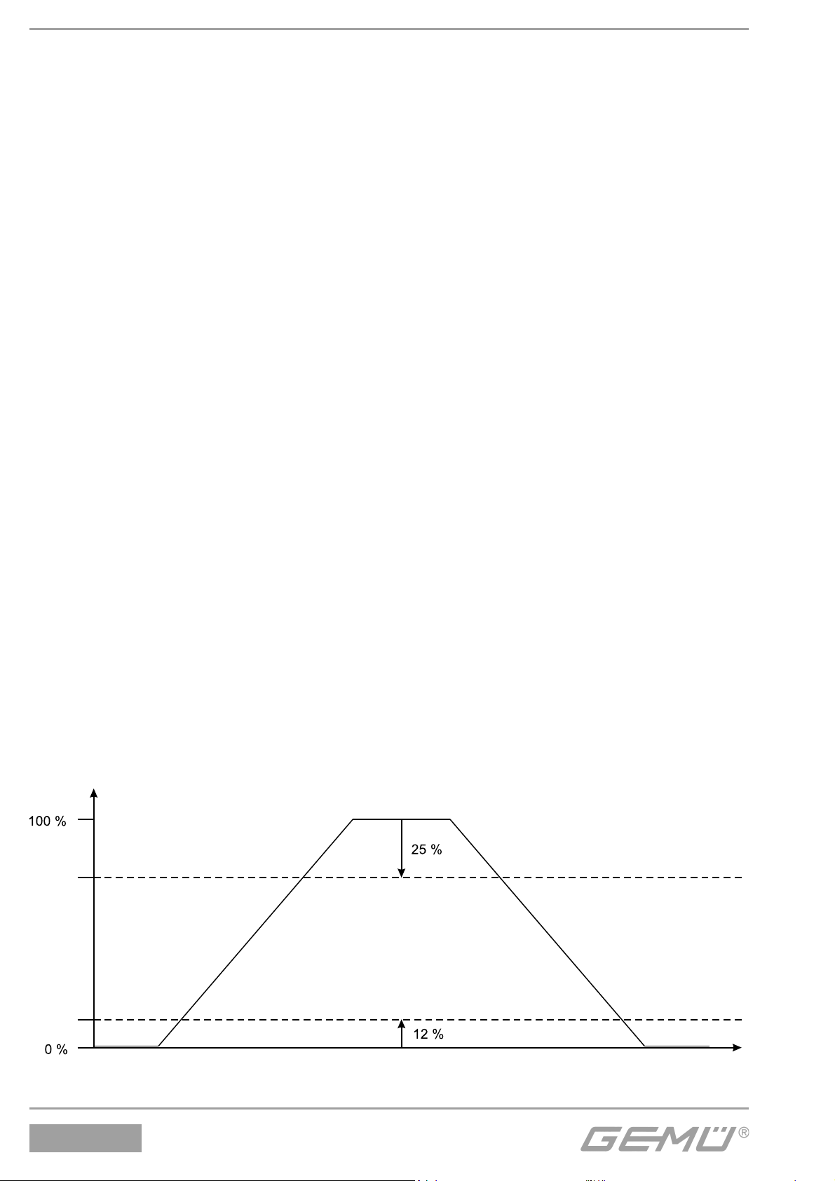
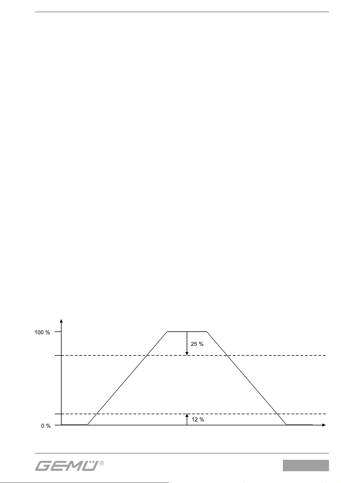
Der Stellungsrückmelder bietet die Möglichkeit, die Schaltpunkte für die AUF- und die ZURückmeldung prozentual zum programmierten Hub einzustellen.
Bsp.: Schaltpunkt AUF 25 %, Schaltpunkt ZU 12 %
Hub
Schaltpunkt
AUF
Schaltpunkt
ZU
Durch diese Toleranzen können betriebsbedingte Veränderungen z.B. bei
Temperaturwechsel kompensiert werden und somit eine sichere Rückmeldung der
1234
10 / 36
Page 11

Endlagen gewährleistet werden.
8.1 24 V Version
Bei der 24 V Version folgendermaßen vorgehen:
Normalbetrieb
Taster betätigen u. halten
0,5 sec.
LEDs 3, 4, 5
leuchten
3 sec.
LEDs 3, 4, 5
aus
Taster
loslassen
Programmiermodus
LEDs 3 und 5
blinken
alternierend
Taster betätigen u. halten
0,5 sec.
LEDs 3, 4, 5
leuchten
3 sec.
LEDs 3, 4, 5
aus
Taster
loslassen
Taster weiter
betätigt (>2 sec.)
Tasterfehler
Taster loslassen
Normalbetrieb
Taster weiter
betätigt (>2 sec.)
Schaltpunkt-
einstellung
11 / 36
Tasterfehler
Taster loslassen
Normalbetrieb
1234
Page 12
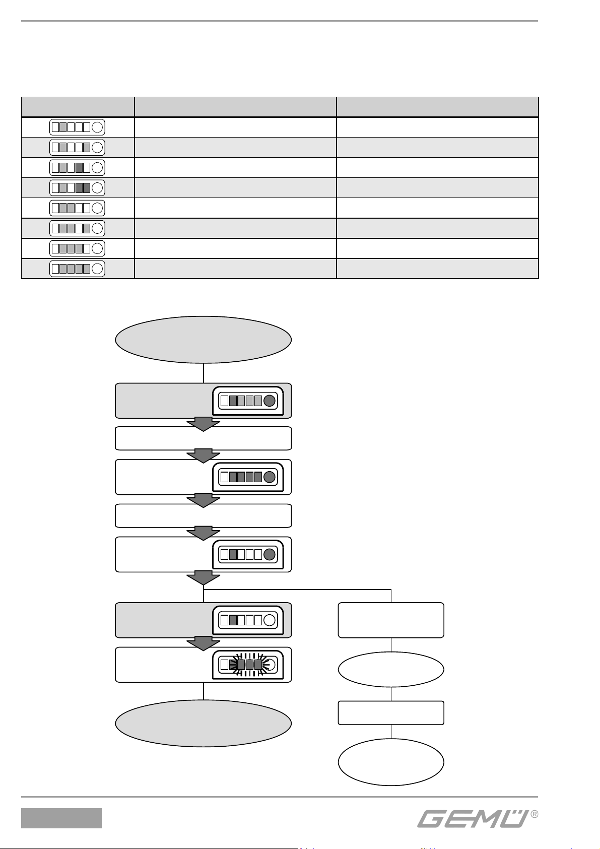
Im Modus Schaltpunkteinstellung werden die unterschiedlichen Schaltpunktgruppen im
1,5 sec. Takt automatisch durchlaufen.
Die gerade aktiven Schaltpunkte werden über die LEDs 3, 4 und 5 folgendermaßen sichtbar
gemacht (* = Werkseinstellung):
LEDs Schaltpunkt AUF [% vom Hub] Schaltpunkt ZU [% vom Hub]
25 6
12 6
66
25* 12*
12 12
612
25 25
12 25
Sind die gewünschten Schaltpunkte erreicht, müssen diese wie folgt quittiert werden:
Schaltpunkt-
einstellung
Taster betätigen u. halten
0,5 sec.
LEDs 3, 4, 5
leuchten
3 sec.
LEDs 3, 4, 5
aus
Taster
loslassen
Taster weiter
betätigt (>2 sec.)
1234
LEDs 3, 4, 5
blinken 2x
Normalbetrieb
Tasterfehler
Taster loslassen
Programmier-
modus
12 / 36
Page 13
8.2 AS-Interface Version
Zusätzlich zur manuellen Schaltpunkteinstellung über den frontseitigen Taster (siehe Kapitel
8.1 "24 V Version"), besteht bei der AS-Interface Version die Möglichkeit die Schaltpunkte
über die Parameterbits P0-P2 einzustellen.
P2 P1 P0 Schaltpunkt AUF [% vom Hub] Schaltpunkt ZU [% vom Hub]
000 25 6
001 12 6
010 6 6
011 25 12
100 12 12
101 6 12
110 25 25
111 12 25
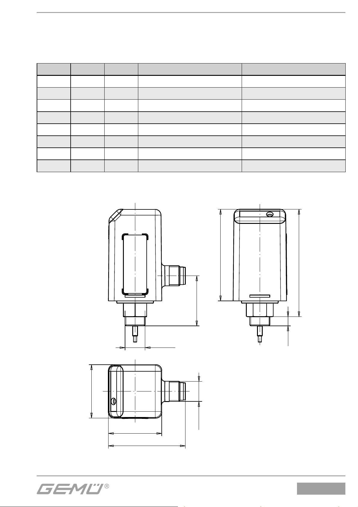
9 Maße
32
32
M12x5
54,9
64,4
30
5,5
M12x1
46,1
Alle Angaben in mm
13 / 36
1234
Page 14
10 Technische Daten
Allgemeines
Schutzart nach EN 60529 IP 65
Schutzklasse III
Einbaulage beliebig
Befestigung M12 x 1 Gewinde
Zulassungen AS-Interface Zul.Nr. 65101
Richtlinien
EG-EMV-Richtlinien 89/336/EWG
Störaussendung EN 50081-1
Störfestigkeit EN 61000-6-2
EG Niederspannungsrichtlinien 73/23/EWG
Betriebsbedingungen
Umgebungstemperatur -10 °C ... +70 °C
Lagertemperatur -20 °C ... +70 °C
Werkstoff e
Gehäuseoberteil PSU schwarz
Gehäuseunterteil PSU schwarz
Dichtelemente NBR, EPDM
Sicherungsring A2
Elektrische Daten (000Z Version)
Spannungsversorgung
Spannungsversorgung U
Welligkeit ± 2 V (<150 Hz)
bei Nennspannung 24 V DC
Leistungsaufnahme typ. 0,85 W
Stromaufnahme typ. 35 mA
Einschaltdauer 100 % ED
Eingänge
Programmiereingang 24 V DC
Low: 0 ... +8 V DC
High: +15 V DC ... +U
Ausgänge
Stellungsrückmeldungen AUF/ZU
Kontaktart 24 V DC, PNP-schaltend
Schaltspannung U
Spannungsabfall V
bei 200 mA Laststrom
Schaltstrom ≤ 200 mA
Signalverarbeitung (siehe Schaltcharakteristik)
Signaldelay td1 ≤ 100 ms
Signaldelay td2 < 125 ms
Signalabstand ta 3 ms
Schalthysterese 0,15 mm
Elektrischer Anschluss
Elektrischer Anschluss 5-poliger M12 Rundstecker
Messbereich
Mindesthub 1 mm
Maximalhub 10 mm
Genauigkeit ± 0,1 mm
24 V DC (16-32 V DC)
V
- V
V
drop
≤ 0,2 V
drop
V
Elektrische Daten (A3Z Version)
Spannungsversorgung
Spannungsversorgung U
26,5 ... 31,6 V DC
V
Leistungsaufnahme typ. 0,85 W
Stromaufnahme max. 45 mA
Einschaltdauer 100 % ED
Eingänge AS-Interface
(Betrachtungsweise vom AS-Interface Master aus)
Bit Funktion Logik
DI0 Anzeige 1 = Ventil in Stellung AUF
Stellung AUF 0 = Ventil nicht in Stellung AUF
DI1 Anzeige 1 = Ventil in Stellung ZU
Stellung ZU 0 = Ventil nicht in Stellung ZU
DI3 Fehler 2 s. Tabelle Fehlerauswertung
FID Fehler 1 s. Tabelle Fehlerauswertung
Ausgänge AS-Interface
(Betrachtungsweise vom AS-Interface Master aus)
Bit Funktion Logik
DO2 Betriebsmodus 1 = Programmiermodus
0 = Normalbetrieb
Parameterausgänge AS-Interface
Bit Funktion Logik
P0 Schaltpunkte setzen siehe Tabelle Schaltpunkte
P1 Schaltpunkte setzen siehe Tabelle Schaltpunkte
P2 Schaltpunkte setzen siehe Tabelle Schaltpunkte
AS-Interface Schnittstelle
AS-Interface Specification 3.0
AS-Interface Profil 7.A.E
I/O-Code 7
ID-Code A
ID2-Code E
Signalverarbeitung (siehe Schaltcharakteristik)
Signaldelay td1 ≤ 100 ms
Signaldelay td2 < 125 ms
Signalabstand ta 3 ms
Schalthysterese 0,15 mm
Elektrischer Anschluss
Elektrischer Anschluss 5-poliger M12 Rundstecker
Messbereich
Mindesthub 1 mm
Maximalhub 10 mm
Genauigkeit ± 0,1 mm
Optische Anzeige
LED Betriebszustand Farbe
1 Fault Rot
2 Power Gelb / Grün*
3 Open Gelb
4 Error Rot
5 Closed Orange
* AS-Interface Version
1234
14 / 36
Page 15
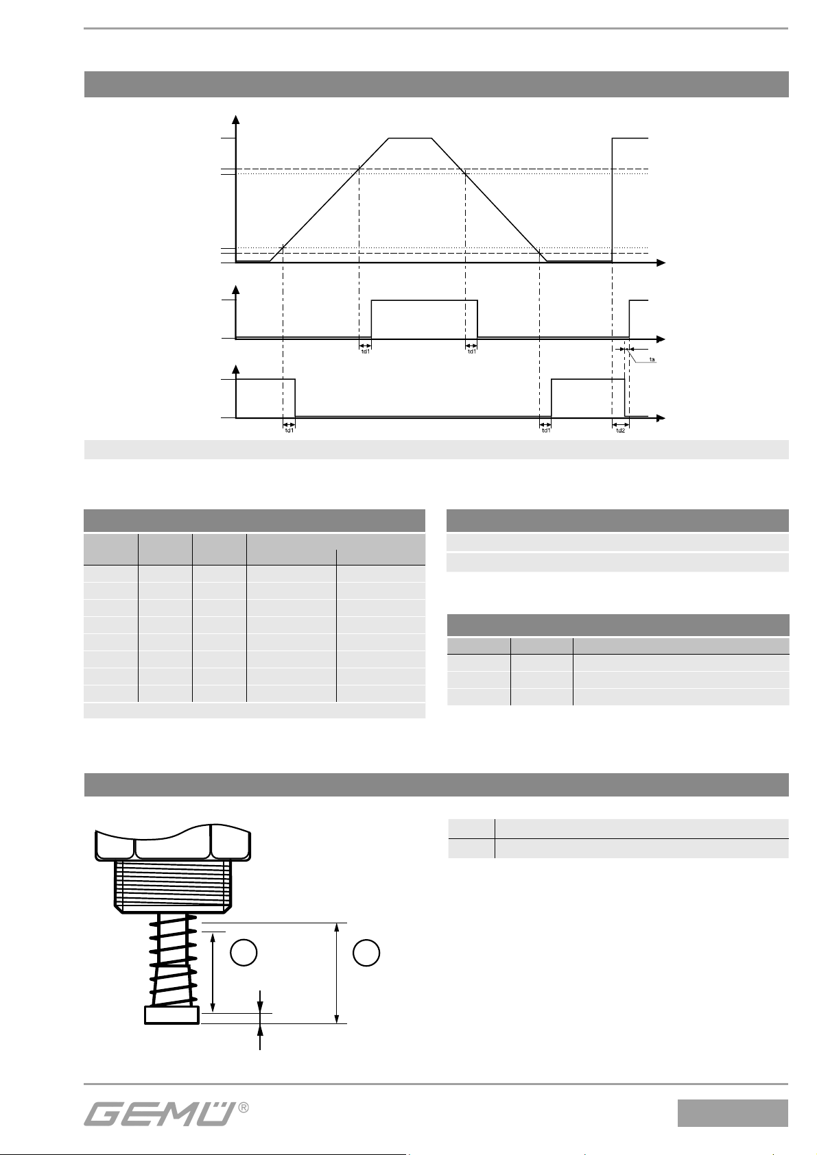
Schaltcharakteristik der Ausgangssignale
Hub %
100 %
Schaltpunkt "AUF"
Schalthysterese
Schalthysterese
Schaltpunkt "ZU"
0 %
Schaltausgang "AUF"
aktiv
inaktiv
Schaltausgang "ZU"
aktiv
inaktiv
Schaltpunkte: In Prozentangaben vom programmierten Hub, vor der jeweiligen Endlage
Diagramm 1: Schaltcharakteristik der Ausgangssignale
t/ms
t/ms
td1: Signaldelay
td2: Signaldelay
ta: Signalabstand
t/ms
Tabelle: Schaltpunkte
LED 3
P2*
*AS-Interface Version
LED 4
P1*
000 25 6
001 12 6
010 6 6
011 25 12
100 12 12
101 6 12
110 25 25
111 12 25
LED 5
P0*
Schaltpunkt
AUF ZU
(% vom Hub)
Lage des Messbereich am Wegmesssystem
Werkseinstellung
Schaltpunkt ZU 12 % (min. 0,32 mm) vom Hub
Schaltpunkt AUF 25 % (min. 0,32 mm) vom Hub
Tabelle: Fehlerauswertung
Fehler 1 Fehler 2 Fehlerfunktion
1 0 Interner Fehler / Taster Fehler
0 1 Programmierungsfehler
1 1 Sensorfehler
1 Zulässiger Messbereich / Maximalhub
2 Max. zulässiger mechanischer Spindelhub
1
10 mm
0,9 mm
2
11,8 mm
15 / 36
1234
Page 16
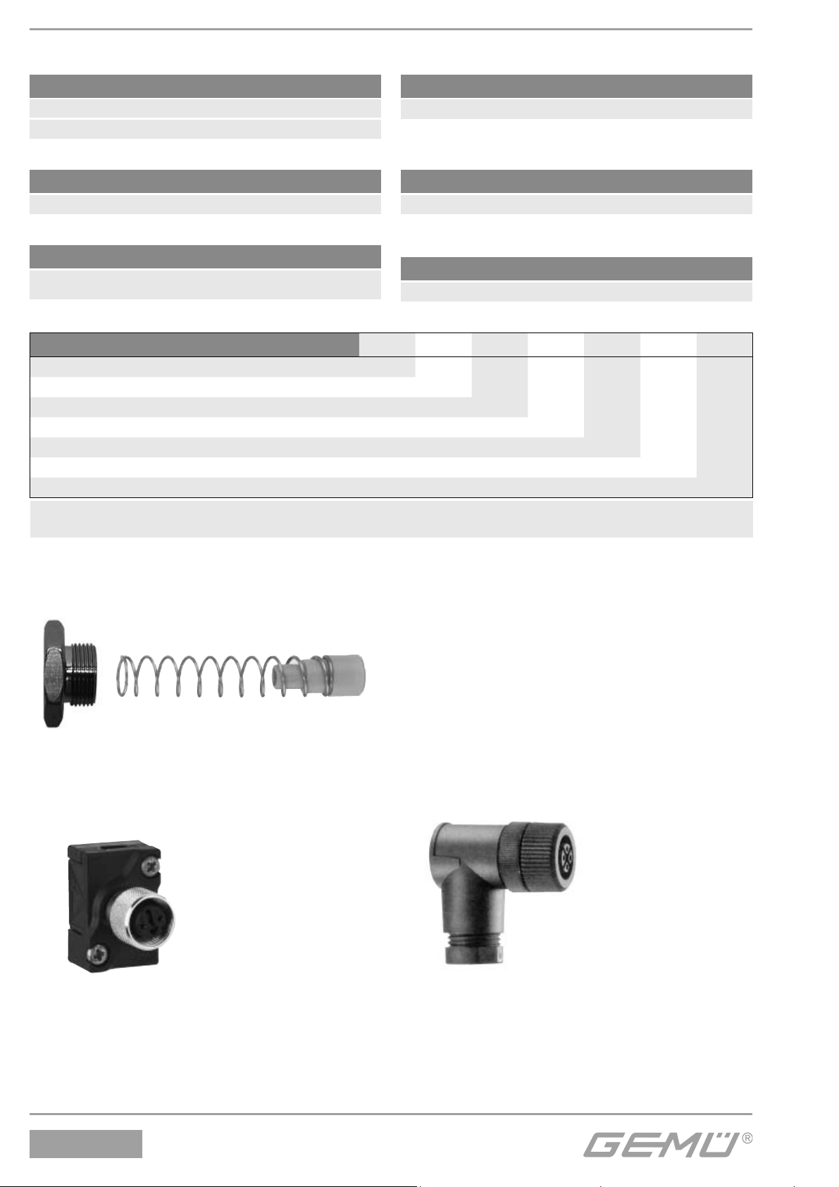
11 Bestelldaten
Feldbus Code
Ohne 000
AS-Interface; 62 Slaves, Spec. 3.0 A3
Zubehör Code
Zubehör Z
Anschluss elektrisch Code
M12 Stecker 5-polig M125
Weggeberlänge Code
10 mm 010
Ein- / Ausgangssignale Code
Programmiereingang
AUF / ZU Stellungsrückmeldung PNP schaltend 1P2D
Bestellbeispiel
Typ 1234
Feldbus (Code) 000
Zubehör (Code) Z
Ein- / Ausgangssignale (Code) 1P2D
Anschluss elektrisch (Code) M125
Weggeberlänge (Code) 010
Gehäuse (Code) H10
Gehäuse Code
Gehäuse PSU schwarz H10
1234 000 Z 1P2D M125 010 H10
Hinweis: Passende Gegensteckdose bitte separat bestellen. Anbausatz 1234 S01Z... ventilbezogen. Bitte separat bestellen.
Angaben des Ventiltyps, DN und Steuerfunktion notwendig.
12 Zubehör
Anbausatz GEMÜ 1234 S01Z...
(Feder + Betätigungsspindel)
Gewindeadapter
(je nach Ausführung)
M12
Anschlussstecker
GEMÜ 4180
für AS-Interface
Version
Gegensteckdose
GEMÜ 1219
unkonfektioniert
und
vorkonfektioniert
1234
16 / 36
Page 17
13 Entsorgung
Entsorgung der Einzelteile nach Materialien
getrennt (Materialien siehe unten), Platine
mit Elektronikbauteilen und Weggeber in
Elektronikschrott.
PSU
Dichtelemente
NBR, EPDM
A2 (VA)
PSU
Hinweis zur Rücksendung:
Aufgrund gesetzlicher
Bestimmungen zum Schutz
der Umwelt und des Personals
ist es erforderlich, dass die
Rücksendeerklärung vollständig
ausgefüllt und unterschrieben
den Versandpapieren beiliegt.
Nur wenn diese Erklärung
vollständig ausgefüllt ist, wird die
Rücksendung bearbeitet!
15 Hinweise
Hinweis:
Alle Rechte wie Urheberrechte
oder gewerbliche Schutzrechte
werden ausdrücklich vorbehalten.
VA
VA
PP
14 Rücksendung
• Elektrischen Stellungsrückmelder reinigen.
• Rücksendeerklärung bei GEMÜ anfordern.
• Rücksendung nur mit vollständig
ausgefüllter Rücksendeerklärung.
Ansonsten erfolgt keine
Gutschrift bzw. keine
Erledigung der Reparatur
sondern eine kostenpflichtige Entsorgung.
Hinweis:
Die Handhabung, Montage und
Inbetriebnahme, sowie Einstellund Justierarbeiten, dürfen
ausschließlich von autorisiertem
Fachpersonal durchgeführt
werden.
Hinweis:
Anschluss- und Justierarbeiten
dürfen nur von autorisiertem
Fachpersonal durchgeführt
werden. Für Schäden welche durch
unsachgemäße Handhabung
oder Fremdeinwirkung entstehen,
übernimmt der Hersteller
keinerlei Haftung. Nehmen Sie im
Zweifelsfall vor Inbetriebnahme
Kontakt mit uns auf.
Hinweis zur
Mitarbeiterschulung:
Zur Mitarbeiterschulung nehmen
Sie bitte über die Adresse auf der
letzten Seite Kontakt auf.
Im Zweifelsfall oder bei Missverständnissen
ist die deutsche Version des Dokuments
ausschlaggebend!
17 / 36
1234
Page 18

16 EG-Konformitätserklärung
Konformitätserklärung
Wir, die Firma GEMÜ Gebr. Müller Apparatebau GmbH & Co. KG
Fritz-Müller-Straße 6-8
D-74653 Ingelfingen
erklären, dass das unten aufgeführte Produkt den folgenden Richtlinien entspricht:
• Niederspannungsrichtlinie 73/23/EWG
• EMV-Richtlinie 89/336/EWG
Angewandte Normen:
• Störfestigkeit EN 61000-6-2
• Störaussendung EN 50081-1
Produkt: GEMÜ 1234
Joachim Brien
Leiter Bereich Technik
Ingelfingen-Criesbach, Juni 2015
1234
18 / 36
Page 19

Contents
1 Notes for your safety 20
1.1 General notes 20
1.2 Explanation of symbols and signs 20
1.3 Safety notes 21
1.4 Information on use in damp conditions 21
2 Function 21
2.1 24 V version 22
2.2 AS-Interface version 22
3 Correct use 23
4 Manufacturer’s information 23
4.1 Delivery and performance 23
4.2 Storage 23
4.3 Tools needed 23
5 Assembly / Disassembly 24
5.1 Mounting kit assembly 24
5.2 Electrical position indicator mounting 24
5.3 Disassembly 25
6 Electrical connections 25
6.1 24 V version 25
6.2 AS-Interface version 25
7 End position programming 26
7.1 24 V version 26
7.2 AS-Interface version 27
8 Switch point setting 27
8.1 24 V version 28
8.2 AS-Interface version 30
9 Dimensions 30
10 Technical data 31
11 Order data 33
12 Accessories 33
13 Disposal 34
14 Returns 34
15 Information 34
16 EC declaration of conformity 35
19 / 36
1234
Page 20

1 Notes for your safety
Please read the following notes carefully and observe them!
The manufacturer shall undertake no responsibility for the GEMÜ 1234 electrical position
indicator if these safety notes are not observed.
1.1 General notes
Prerequisites for the correction function of the GEMÜ 1234 electrical position indicator:
• Correct transport and storage
• Installation and commissioning by trained personnel
• Operation according to these installation, operating and maintenance instructions
• Recommended maintenance
The GEMÜ 1234 electrical position indicator must be used in accordance with
these directions. All information in these installation, operating and maintenance
instructions regarding operation, servicing and maintenance must be observed and
applied. If the information is not observed, the operator's guarantee rights and the
manufacturer's legal liability cease.
Therefore, you must observe:
• the contents of these installation, operating and maintenance instructions
• the relevant safety regulations for the installation and operation of electrical systems
• that this device must not be used in potentially explosive areas.
The regulations, standards and guidelines named in these installation, operating and
maintenance instructions are only applicable in Germany. If the GEMÜ 1234 electrical
position indicator is used in other countries, the local applicable regulations must be
observed. When dealing with harmonised European norms, standards and guidelines, these
apply within the Single European Market. The operator must also adhere to national rules
and guidelines, if applicable.
The descriptions and instructions in these operating instructions refer to the standard
version.
The safety notes do not take into account
• coincidences and events which may occur during installation, operation and servicing.
• local safety regulations which must be adhered to by the operator and any additional
installation personnel.
If you have any questions, please do not hesitate to ask your closest GEMÜ sales office.
1.2 Explanation of symbols and signs
Important information is identified in these installation, operating and maintenance
instructions by the following symbols:
CAUTION
A possibly dangerous situation!
® Non-observance can cause damage to property.
1234
20 / 36
Page 21

1.3 Safety notes
Please observe the items listed in these safety notes, the existing national and European
accident avoidance regulations and any existing operator's internal working, operating and
safety guidelines. Only qualified and trained specialist staff should assemble, electrically
connect and commission the GEMÜ 1234. Use qualified staff for operation, servicing,
inspection and assembly. The areas of responsibility, the monitoring of staff and their
competence areas should be defined precisely by the operator. Train staff with insufficient
knowledge or, if necessary, have them trained by the manufacturer / supplier on order of the
operator. Ensure that all members of staff understand the safety instructions. Ensure that
the power supply equipment is electrically safe. Also ensure that the electrical values are
correct.
If the safety notes are disregarded then persons, the environment and the GEMÜ 1234
electrical position indicator may be endangered. Furthermore, failure to observe the safety
notes may lead to a complete loss of claims rights.
Adhere to legal regulations!
1.4 Information on use in damp conditions
The following information is intended to help when mounting and operating the GEMÜ 1234
electrical position indicator in damp conditions.
• Lay cables and pipework so that condensate or rain water that remains on the pipework /
cables cannot enter the cable glands of the GEMÜ 1234 electrical position indicator
• Check that all cable glands are tight
CAUTION
Under no circumstances whatsoever may the electrical position indicator be cleaned with
a high pressure cleaning device, observe the protection class!
2 Function
The GEMÜ 1234 electrical position indicator has a microprocessor controlled intelligent
position sensor as well as an analogue integrated travel sensor system (stroke). The stroke
is detected by a potentiometer whose spindle is positively connected with the actuator
spindle by means of a mounting kit (spring, operating bush). The electrical position feedback
is made by 24 V DC signals (24 V version) or by AS-Interface.
In addition to the electrical position feedback, the position is optically indicated by LEDs
which can be seen from the top and at the front.
21 / 36
1234
Page 22
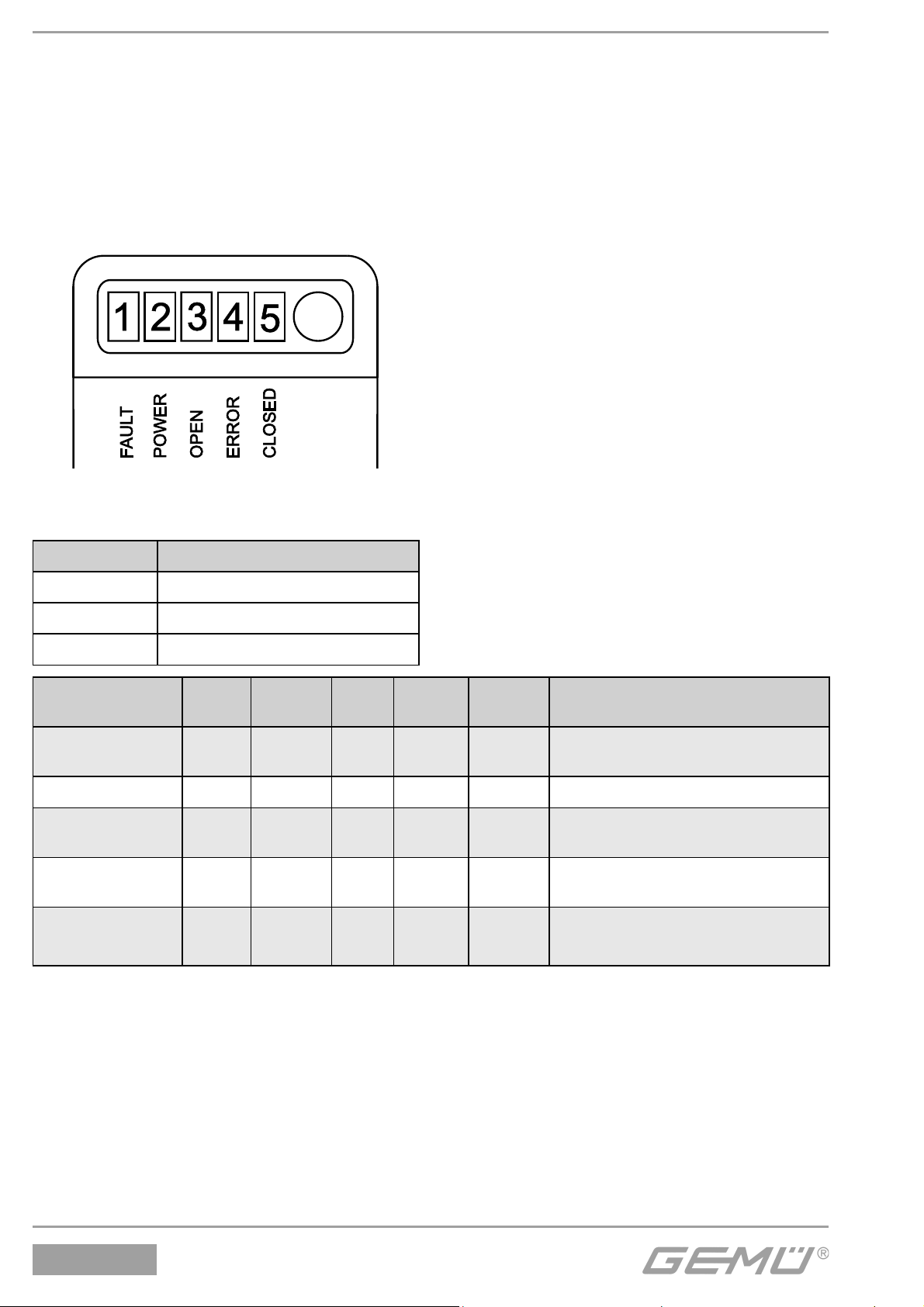
The following functions are optically indicated:
• FAULT → LED1 red
• POWER → LED2 green / yellow
• OPEN → LED3 yellow
• ERROR → LED4 red
• CLOSED → LED5 orange
• Programming mode (see chapter 7 "End position programming")
• Switch point setting (see chapter 8 "Switch point setting")
The following error messages are also signalled by LEDs:
Key LED conditions
X LED lit (on)
O LED flashes
- LED off
Error cause
Button error O X - O -
Programming error - X - X O Re-programme
Sensor error O X O X -
Memory error O X O X O
AS-Interface error X X - - -
LED 1*
FAULT
LED 2
POWER
LED 3
OPEN
LED 4
ERROR
LED 5
CLOSED
Error elimination
Release button
(button was pressed longer than 4s)
Sensor limit exceeded.
Ensure stroke ≤ 10 mm
Re-programme
Second error = faulty
*Indication only active with
AS-Interface version
2.1 24 V version
Power supply and OPEN/CLOSED feedback are via 24 V DC (Switching characteristic see
chapter 10 "Technical data").
2.2 AS-Interface version
Power supply and OPEN/CLOSED feedback are via AS-Interface (Switching characteristic
see chapter 10 "Technical data").
1234
22 / 36
Page 23

3 Correct use
The GEMÜ 1234 electrical position indicator is suitable for use as defined in the data sheet.
In order to ensure correct product function, the following notes should be observed. Pay
attention to the information on the product labels.
Non-observance of these notes and the notes in the general installation, operating and
maintenance instructions will lead to a loss of the guarantee on the GEMÜ 1234 electrical
position indicator and of legal liability.
Only use the GEMÜ 1234 electrical position indicator for electrical and optical position
detection for linear actuators with a maximum stroke of 10 mm (see chapter 10 "Technical
data") in accordance with the data sheet. Any other use or use above and beyond this is not
permitted. GEMÜ shall not be liable for any consequential damage which is solely at the
user's risk.
When planning the use of the device and when operating it, please pay attention to relevant
generally known technical safety regulations. Designers, plant constructors or operators are
always responsible for the positioning and installation of the GEMÜ 1234 electrical position
indicator.
4 Manufacturer’s information
4.1 Delivery and performance
Check the goods for completeness and damage immediately upon receipt.
The scope of delivery is apparent from the dispatch documents.
Use the order numbers to check whether the type and scope has been delivered as ordered.
If the GEMÜ 1234 position indicator is ordered as a complete unit with a valve, these parts
and the accessories belonging to them are supplied ready assembled and factory set.
The GEMÜ position indicator is then ready for immediate operation.
4.2 Storage
Store the electrical position indicator dry in its original packaging. Avoid UV rays and direct
sunlight. Maximum storage temperature 70 °C.
4.3 Tools needed
The tools required for installation and assembly are not included in the scope of delivery!
Use appropriate, functional and safe tools!
23 / 36
1234
Page 24
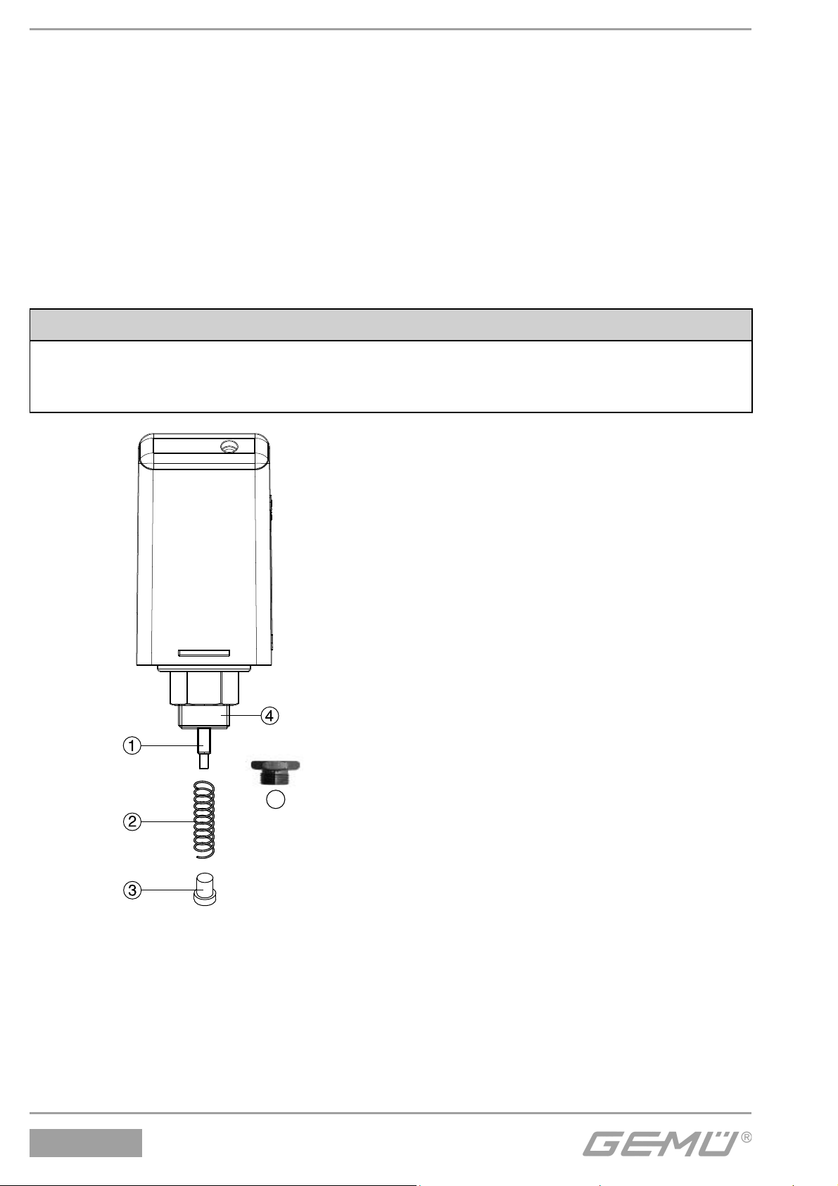
5 Assembly / Disassembly
5.1 Mounting kit assembly
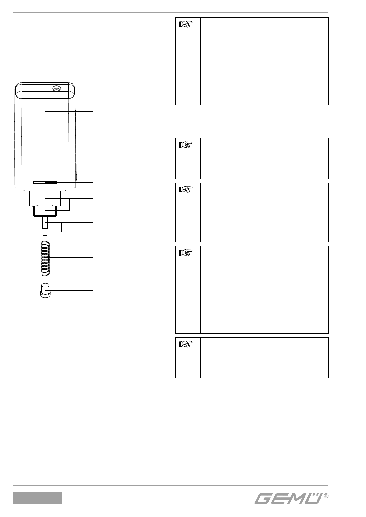
GEMÜ 1234 S01Z ... mounting kits consist of a spring 2, an operating bush 3 and,
dependent on the design, a threaded adapter 5.
Assembly procedure:
• Pull the spindle 1 out
• Push the spring 2 over the spindle 1
• Screw the operating bush 3 onto the spindle thread 1
• If a threaded adapter 5 is included in the kit, screw this onto the M12x1 thread 4
CAUTION
• Do not release the travel sensor suddenly!
• Do not scratch the spindle!
• Do not overtighten the thread of the operating bush!
5
5.2 Electrical position indicator mounting
When retrofitting the position indicator to a process valve, please proceed as follows:
• Remove mechanical position indicator (if existing)
• Remove the vent plug (if existing)
• Screw the position indicator with the mounting kit into the valve
• Tighten the hexagon nut SW 27 with max. 4 Nm
1234
24 / 36
Page 25
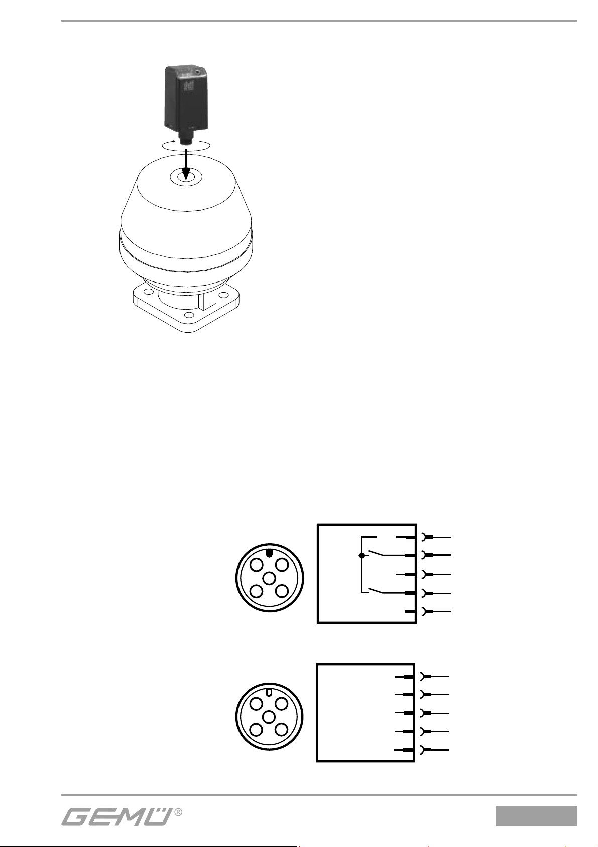
• Gently press in the external cable socket (do not force it) and screw it on
• Connect supply voltage (see chapter 6 "Electrical connections")
5.3 Disassembly
Disassembly of the mounting kit / the electrical position indicator is in the opposite order to
the assembly procedure (see chapters 5.1 - 5.2).
6 Electrical connections
6.1 24 V version
GEMÜ 1234
mit 5-poligem M12
Anschlussstecker
U+
2
1
5
3
4
0 V
1
Uv, 24 V DC
2
Signal OPEN
3
Uv, GND
4
Signal CLOSED
5
Programming input
6.2 AS-Interface version
GEMÜ 1234
AS-Interface
mit 5-poligem M12
Anschlussstecker
AS-i +
2
1
5
4
3
AS-i -
1
3
AS-i +
AS-i -
AS-Interface
25 / 36
1234
Page 26
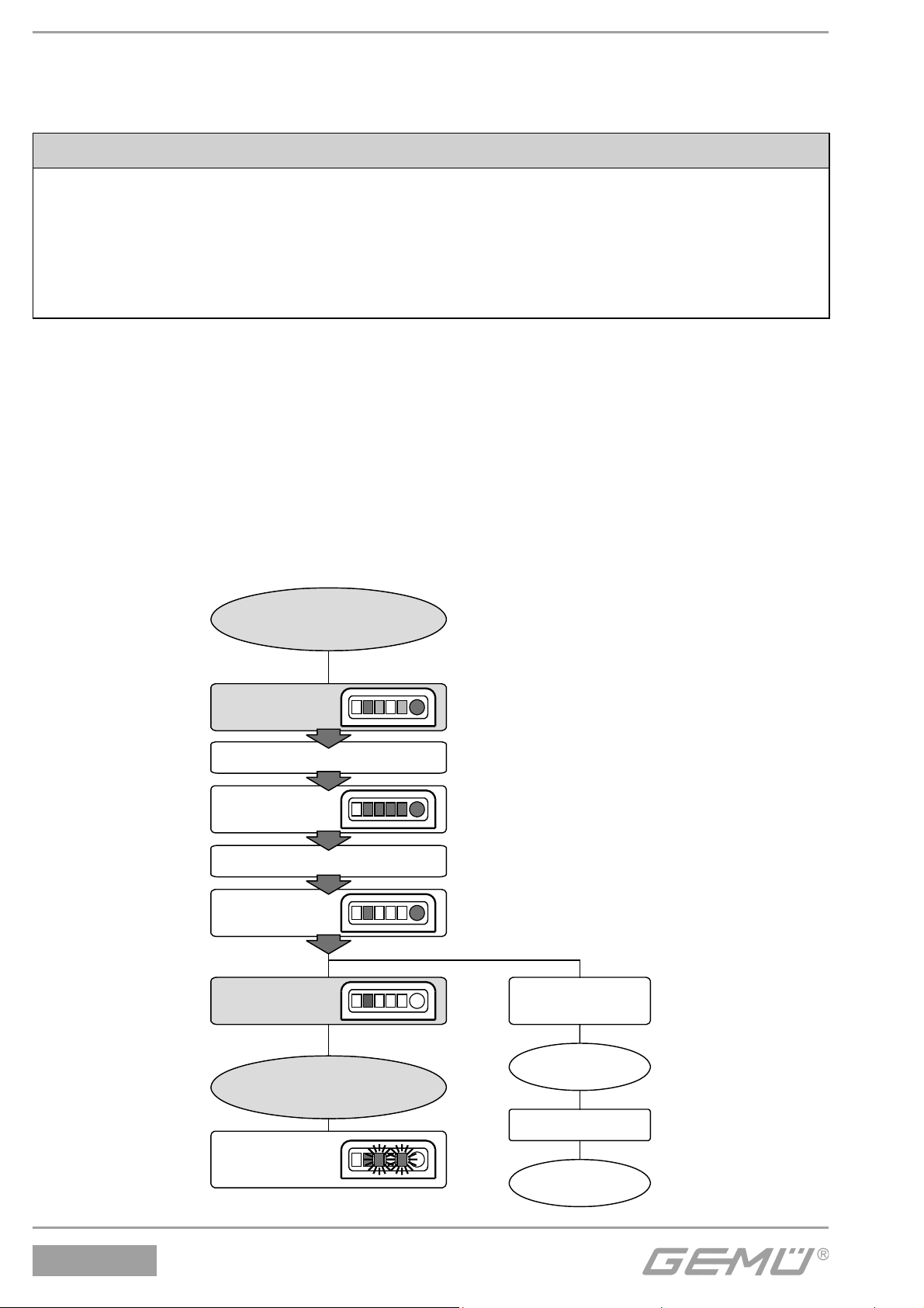
7 End position programming
The end position feedback is already programmed for position indicators factory-mounted to
the process valve.
CAUTION
• It is necessary to re-programme the end positions if the actuator is replaced or later
refitted (and also if retightening / replacing the shut-off diaphragm)
• When using a stroke limiter, observe the required minimum stroke (see chapter 10
"Technical data")
• The GEMÜ 1234 travel sensor always requires a slight pre-tension, i.e. the spindle must
always be slightly operated (see chapter 10 "Technical data")
7.1 24 V version
The end positions can be programmed manually on site or externally via a programming
input (pin 5).
Manual programming
If programming manually, the programming mode must be switched on by pressing the button.
The device automatically detects the programming end and switches to normal operation.
Procedure for manual end position programming:
• Put the electrical position indicator into the programming mode:
Normal operation
Press button
and hold
0.5 sec.
LEDs 3, 4, 5
lit (on)
3 sec.
LEDs 3, 4, 5
off
Release
button
Button not
released (>2 sec.)
1234
Programming mode
LEDs 3 and 5
flash
alternately
Button error
Release button
Normal operation
26 / 36
Page 27
• Open valve until end position is reached
• Close valve until end position is reached
• End positions are set
External programming
If programming externally, the programming mode is switched on via a programming input
(pin 5). The device automatically detects the programming end and switches to normal operation.
Procedure for external end position programming:
• Connect supply voltage 24 V DC (pin 1), GND (pin 3)
• Short signal (24 V DC) to pin 5 (programming input)
• Yellow LED is lit and orange and green LEDs flash alternately
• Open valve until end position is reached
• Close valve until end position is reached
• End positions are set
7.2 AS-Interface version
In addition to on-site programming (see chapter 7.1 "24 V version" / Manual programming),
the end positions can also be programmed via AS-Interface.
Procedure for programming via AS-Interface:
• Set DO2 = 1 (position indicator is in programming mode)
• Open valve until end position is reached
• Close valve until end position is reached
• Set DO2 = 0 (position indicator is in normal operation)
• End positions are set
8 Switch point setting
The electrical position indicator provides the possibility within its software to set tolerances
for the point at which the switchbox will register the open or closed positions after being
programmed.The tolerances are a defined as a percentage of the actual programmed stroke.
Example: Switch point OPEN set at 25 %, switch point CLOSED set at 12 %. This means
the switchbox will still register the OPEN position within 25 % of the programmed OPEN set
point and within 12 % of the actual CLOSED programmed set point.
Stroke
Switch
point
OPEN
Switch
point
CLOSED
These tolerances enable compensation of operational changes e.g. temperature changes to
ensure reliable end position feedback.
27 / 36
1234
Page 28
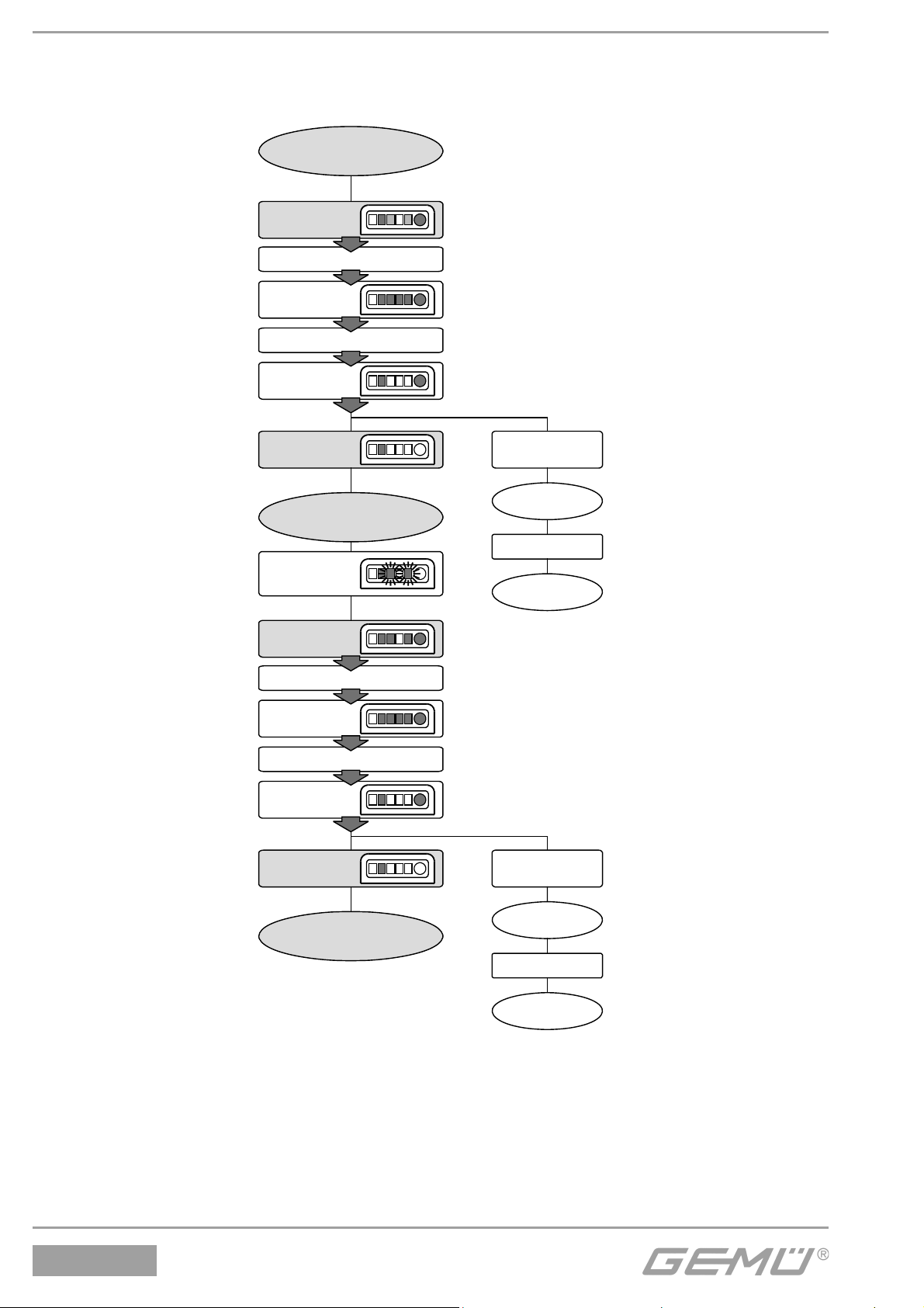
8.1 24 V version
Procedure for 24 V version:
Normal operation
Press button
and hold
0.5 sec.
LEDs 3, 4, 5
lit (on)
3 sec.
LEDs 3, 4, 5
off
Release
button
Programming mode
LEDs 3 and 5
flash
alternately
Press button
and hold
0.5 sec.
LEDs 3, 4, 5
lit (on)
3 sec.
LEDs 3, 4, 5
off
Release
button
Button not
released (>2 sec.)
Button error
Release button
Normal operation
Button not
released (>2 sec.)
1234
Switch point
setting
Button error
Release button
Normal operation
28 / 36
Page 29
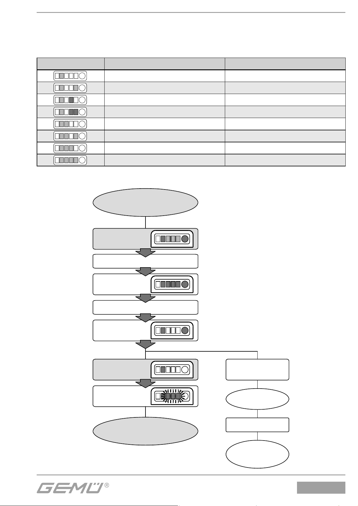
In the switch point setting mode the various switch point groups are automatically passed
through in a 1.5 sec. cycle.
The currently active switch points are indicated via LEDs 3, 4 and 5 as follows (* = factory
setting):
LEDs Switch point OPEN [% of stroke] Switch point CLOSED [% of stroke]
25 6
12 6
66
25* 12*
12 12
612
25 25
12 25
When the required switch points are reached they have to be acknowledged as follows:
Switch point
setting
Press button
and hold
0.5 sec.
LEDs 3, 4, 5
lit (on)
3 sec.
LEDs 3, 4, 5
off
Release
button
Button not
released
(>2 sec.)
LEDs 3, 4, 5
flash twice
Normal operation
29 / 36
Button error
Release button
Programming
mode
1234
Page 30
8.2 AS-Interface version
In addition to manual switch point setting via the fascia button (see chapter 8.1
"24 V version"), the switch points of the AS-Interface version can also be set via parameter
bits P0-P2.
P2 P1 P0 Switch point OPEN [% of stroke]
000 25 6
001 12 6
010 6 6
011 25 12
100 12 12
101 6 12
110 25 25
111 12 25
Switch point CLOSED [% of stroke]
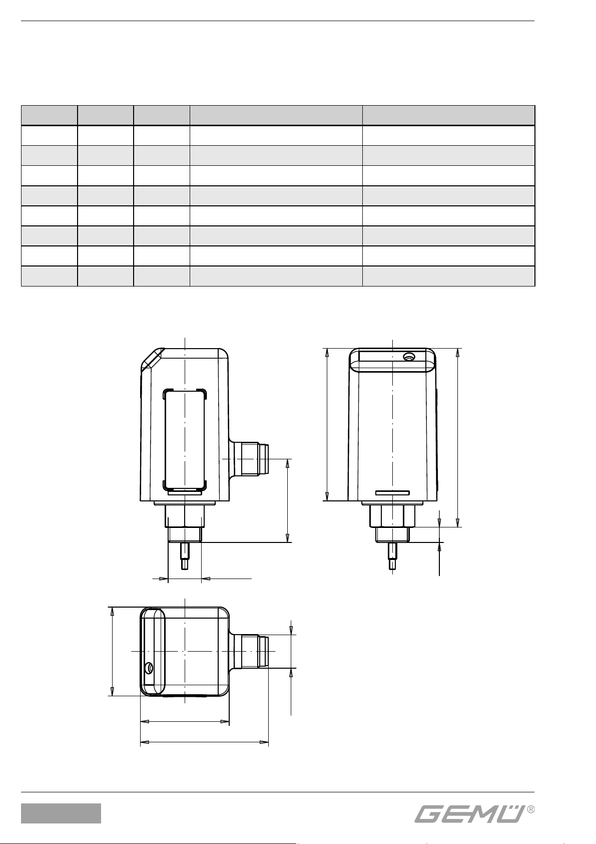
9 Dimensions
32
32
M12x5
54,9
64,4
30
5,5
M12x1
1234
46,1
All dimensions in mm
30 / 36
Page 31
10 Technical data
General information
Protection class to EN 60529 IP 65
Electrical protection class III
Mounting position Optional
Mounting M12 x 1 thread
Certificates AS-Interface cert. no. 65101
Directives
EC-EMC directive 89/336/EEC
Interference emission EN 50081-1
Interference resistance EN 61000-6-2
EC low voltage directive 73/23/EEC
Operating conditions
Ambient temperature -10 °C to +70 °C
Storage temperature -20 °C to +70 °C
Materials
Housing cover PSU black
Housing base PSU black
Seals NBR, EPDM
Retaining ring A2
Electrical data (000Z version)
Power supply
Power supply U
Ripple ± 2 V (<150 Hz)
at rated voltage 24 V DC
Power consumption typ. 0.85 W
Current consumption typ. 35 mA
Rating continuously rated
Inputs
Programming input 24 V DC
Low: 0 ...+8V DC
High: +15 V DC ... +U
Outputs
Position feedback OPEN/CLOSED
Type of contact 24 V DC, PNP
Switching voltage U
Voltage drop V
at 200 mA on-load current
Switching current ≤ 200 mA
Signal processing (see switching characteristic)
Signal delay td1 ≤ 100 ms
Signal delay td2 < 125 ms
Signal interval ta 3 ms
Switching hysteresis 0.15 mm
Electrical connection
Electrical connection 5-pin M12 plug
Measuring range
Minimum stroke 1 mm
Maximum stroke 10 mm
Accuracy ± 0.1 mm
24 V DC (16-32 V DC)
V
- V
V
drop
≤ 0.2 V
drop
V
Electrical data (A3Z version)
Power supply
Power supply U
26.5 ... 31.6 V DC
V
Power consumption typ. 0.85 W
Current consumption max. 45 mA
Rating continuously rated
Inputs AS-Interface
(as seen from the AS-Interface master)
Bit Function Logic
DI0 Indication 1 = valve in OPEN position
OPEN position 0 = valve not in OPEN position
DI1 Indication 1 = valve in CLOSED position
CLOSED position
0 = valve not in CLOSED position
DI3 Error 2 see Error analysis table
FID Error 1 see Error analysis table
Outputs AS-Interface
(as seen from the AS-Interface master)
Bit Function Logic
DO2 Operating mode 1 = programming mode
0 = normal operation
Parameter outputs AS-Interface
Bit Function Logic
P0 Setting of switch points see Switch point table
P1 Setting of switch points see Switch point table
P2 Setting of switch points see Switch point table
AS-Interface
AS-Interface specification 3.0
AS-Interface profile 7.A.E
I/O code 7
ID code A
ID2 code E
Signal processing (see switching characteristic)
Signal delay td1 ≤ 100 ms
Signal delay td2 < 125 ms
Signal interval ta 3 ms
Switching hysteresis 0.15 mm
Electrical connection
Electrical connection 5-pin M12 plug
Measuring range
Minimum stroke 1 mm
Maximum stroke 10 mm
Accuracy ± 0.1 mm
Optical indication
LED Operating condition Colour
1 Fault Red
2 Power Yellow / Green*
3 Open Yellow
4 Error Red
5 Closed Orange
* AS-Interface version
31 / 36
1234
Page 32
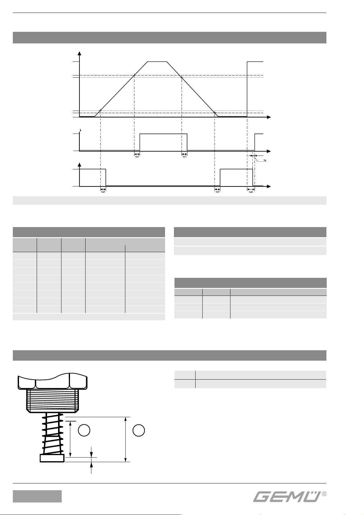
Switching characteristic of output signals
Stroke %
100 %
Switch point "OPEN"
Switching hysteresis
Switching hysteresis
Switch point "CLOSED"
0 %
Switching output "OPEN"
active
inactive
Switching output "CLOSED"
active
inactive
Switch points: The data in percent refer to the programmed stroke, before each end position
Diagram 1: Switching characteristic of output signals
t/ms
t/ms
td1: Signal delay
td2: Signal delay
ta: Signal interval
t/ms
Table: Switch points
LED 3
P2*
*AS-Interface version
LED 4
P1*
000 25 6
001 12 6
010 6 6
011 25 12
100 12 12
101 6 12
110 25 25
111 12 25
LED 5
P0*
Switch point
OPEN CLOSED
(% of stroke)
Position of measuring range at travel sensor system
Factory setting
Switch point CLOSED 12 % (min. 0.32 mm) of stroke
Switch point OPEN 25 % (min. 0.32 mm) of stroke
Table: Error analysis
Error 1 Error 2 Error function
1 0 Internal error / button error
0 1 Programming error
1 1 Sensor error
1 Permissible measuring range / maximum stroke
2 Max. permissible mechanical spindle stroke
1234
1
10 mm
2
11,8 mm
0,9 mm
32 / 36
Page 33
11 Order data
Field bus Code
Without 000
AS-Interface; 62 slaves, Spec. 3.0 A3
Accessory Code
Accessory Z
Electrical connection Code
M12 5-pin plug M125
Travel length Code
10 mm 010
Input / output signals Code
Programming input
OPEN / CLOSED position feedback
PNP 1P2D
Order example
Type 1234
Field bus (code) 000
Accessory (code) Z
Input / output signals (code) 1P2D
Electrical connection (code) M125
Travel length (code) 010
Housing (code) H10
Housing Code
Black PSU housing H10
1234 000 Z 1P2D M125 010 H10
Note: Please order the correct cable socket separately. Mounting kit 1234 S01Z... dependent on valve type. Please order
separately specifying valve type, DN and control function.
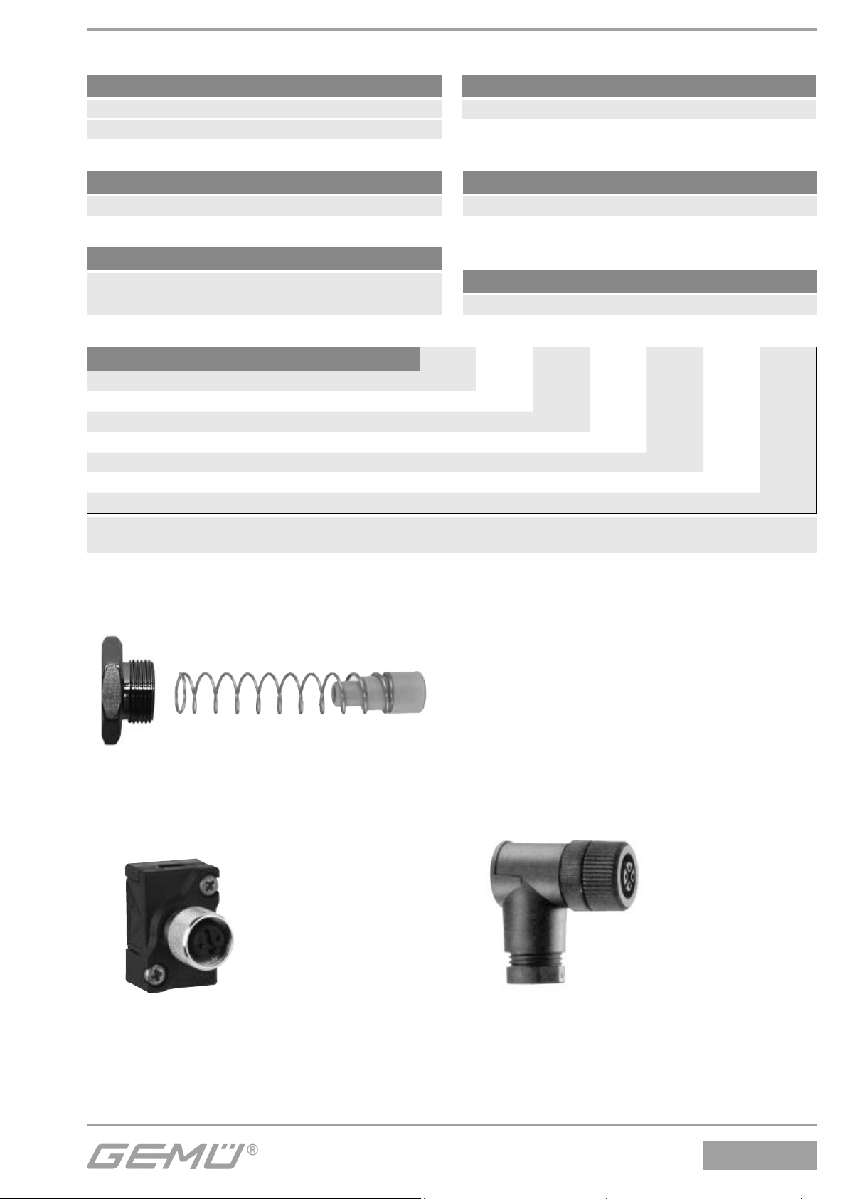
12 Accessories
Mounting kit GEMÜ 1234 S01Z...
(spring + operating bush)
Threaded adapter
(dependent on version)
M12 cable socket
Connector GEMÜ 4180
for AS-Interface version
GEMÜ 1219
pre-fitted with
cable or without
cable
33 / 36
1234
Page 34
13 Disposal
Disposal of the individual components
should be separated by materials (materials
see below), circuit boards with electronic
components and travel sensor placed in
electronics scrap.
PSU
Note for returns:
Legal regulations for the protection
of the environment and personnel
require that the completed and
signed goods return declaration
is included with the dispatch
documents. Returned goods can
be processed only when this
declaration is completed.
15 Information
Seals NBR,
EPDM
A2 (St. steel)
PSU
Stainless steel
Stainless steel
PP
14 Returns
• Clean the electrical position indicator.
• Request a goods return declaration form
from GEMÜ.
• Returns must be made with a completed
declaration of return.
Note:
All rights including copyright
and industrial property rights are
expressly reserved.
Note:
Handling, assembly and
commissioning, in addition to
setting and adjustment must be
performed only by authorised
trained personnel.
Note:
Connection and adjustments
may only be carried out by
authorised trained personnel. The
manufacturer shall assume no
liability whatsoever for damages
caused by improper handling or
third-party actions. In case of doubt
contact us before commissioning.
Note on staff training:
Please contact us at the address
on the last page for staff training
information.
If not completed, GEMÜ cannot process
credits or
repair work
but will dispose of the goods at the
operator’s expense.
1234
Should there be any doubts or
misunderstandings in the preceding text,
the German version of this document is the
authoritative document!
34 / 36
Page 35

16 EC declaration of conformity
Declaration of Conformity
Hereby we GEMÜ Gebr. Müller Apparatebau GmbH & Co. KG
Fritz-Müller-Straße 6-8
D-74653 Ingelfingen
declare that the product listed below complies with the following directives:
• Low Voltage Directive 73/23/EEC
• EMC Directive 89/336/EEC
Applied standards:
• Interference resistance EN 61000-6-2
• Interference emission EN 50081-1
Product: GEMÜ 1234
Joachim Brien
Head of Technical Department
Ingelfingen-Criesbach, June 2015
35 / 36
1234
Page 36

VENTIL-, MESS- UND REGELSYSTEME
VALVES, MEASUREMENT AND CONTROL SYSTEMS
GEMÜ Gebr. Müller Apparatebau GmbH & Co. KG · Fritz-Müller-Str. 6-8 · D-74653 Ingelfi ngen-Criesbach
Telefon +49(0)7940/123-0 · Telefax +49(0)7940/123-192 · [email protected] · www.gemu-group.com
Änderungen vorbehalten · Subject to alteration · 06/2015 · 88255530
 Loading...