

Page 1

WRTR-262GN User Manual
Chapter 1 Product Overview
Features
Supports IEEE802.11n and IEEE802.11b/g
With support for Wireless-N, Wireless-G, and Wireless-B standards, WRTR-262GN can transfer data to
and from all standard 2.4 GHz wireless clients.
Dual speed mode
Dual speed mode makes wireless transmission faster by using 2 channels, allowing 150Mbps data
transmission.
Support WPS
Both WPS (Wi-Fi Protected Setup) is supported.
Security Features
WRTR-262GN is equipped with following security features:
• WPS
• WPA-PSK (TKIP/AES)
• WPA2-PSK(TKIP/AES)
• WPA/WPA2 mixed PSK
• WEP(128/64bit)
• Privacy Separator
• MAC address access restriction
• Deny Any Connection/SSID stealth feature
• Web configuration screen with password
• Firewall feature with easy rules
Automatic Channel Selection
Monitors wireless interference and automatically assigns the clearest, best channel.
Page 2

Initialization
To restore settings back to the factory defaults, hold down the Reset button on the side of the unit.
Browser Based Administration
This unit can be easily configured from a web browser on your computer.
150 Mbps High Speed Mode
150 Mbps is the link speed of WRTR-262GNwhen using Wireless-N mode. It represents actual wireless
data speeds, including overhead. Because the overhead is not available for user data transfer, usable
wireless throughput will be substantially slower.
Package Contents
Following items are included in your WRTR-262GN. If any of the items are missing, please contact your
vender.
• Main unit...............................................................................................1
• Screws..................................................................................................1
• AC adapter............................................................................................1
• LAN cable..............................................................................................1
• Quick Setup Guide................................................................................1
• Manual...................................................................................................1
Hardware Overview
Front Panel LED
Page 3
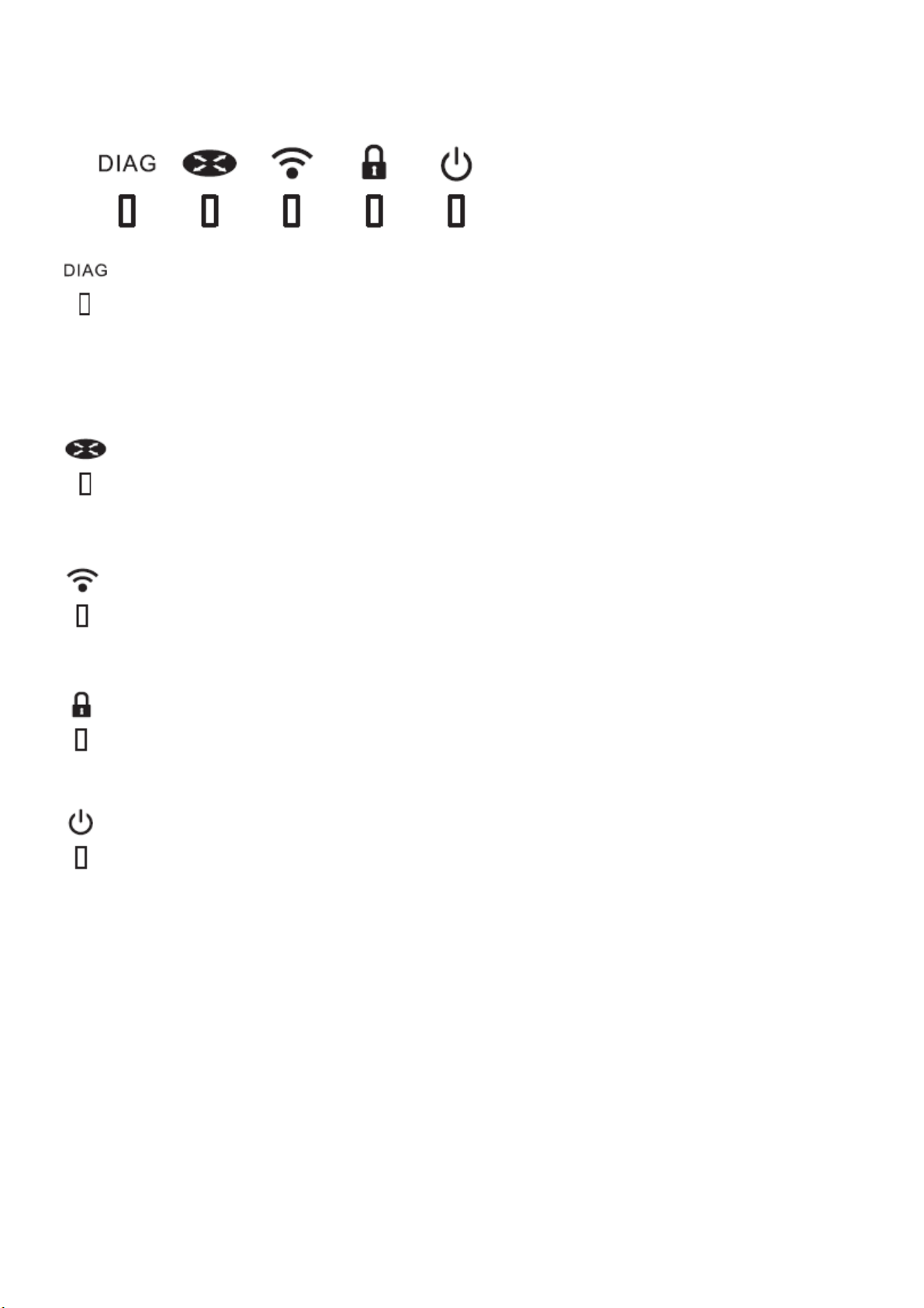
DIAG LED (Red) This indicates the status of the unit depending on the number of blinks per
cycle.
Note: When the unit is first turned on or restarted, the Diag LED will blink for almost a minute during
boot. This is normal.
Internet LAN 1-4 LED (Green)
On: functionality is enabled
Off: functionality is disabled
WIRELESS LED (Green)
Indicates wireless LAN status.
Blinking: Wireless LAN is transmitting
On: Wireless LAN is connected but not active
SECURITY LED (Amber) Indicates security status.
Off: Encryption is not set
On: Encryption has been set
POWER LED (Green)
On: The AC adapter is connected
Off: The AC adapter is not connected
Back Panel
Page 4
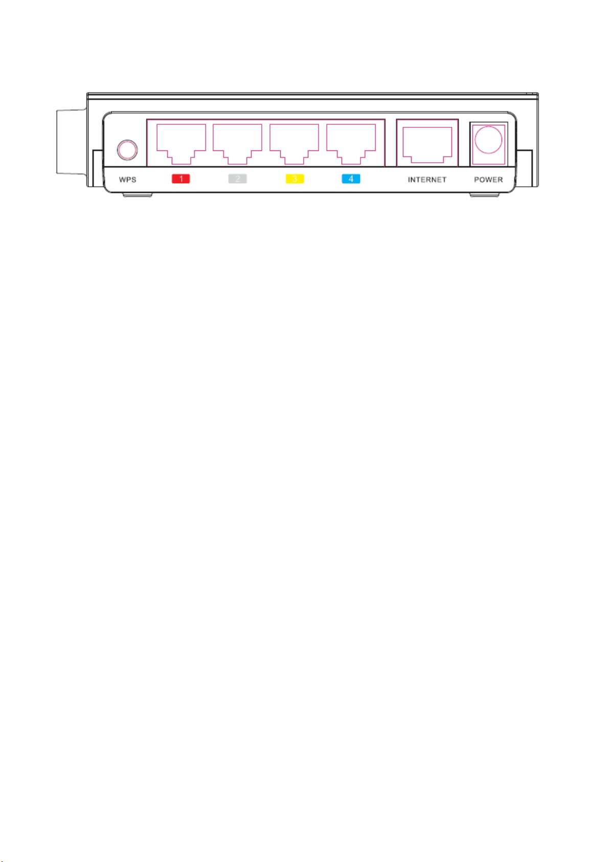
WPS Botton
Hold down this button until the Security LED flashes (about 1 second), while the unit’s power is on,
initiates WPS mode, allowing the unit to exchange security keys with WPS compatible devices.
LAN Port 1~4
Connect your computer, hub, or other Ethernet devices to these ports. This switching hub supports
10Mbps and 100Mbps connections.
INTERNET Port
10Mbps and 100Mbps connections are supported.
Note: In bridge/AP mode, the Internet port becomes a regular LAN port, for a total of 5 usable LAN
ports.
Power Connector
Connect the included AC adapter.
Left Side
Page 5

RESET Button Holding this button until the Diag LED comes on, while the unit's power is on, will
initialize its settings.
Chapter 2 Installation
Manual Setup
To configure your WRTR-262GN manually, follow the procedure below.
1. Turn off your computer and modem
Page 6

2. Unplug the LAN cable which connects your computer and modem.
modem turn off the computer
disconnect disconnect
3. Plug one end of the LAN cable into your modem and the other side to the Internet port of
WRTR-262GN. Turn on your modem.
modem
connect
connect Internet port
WRTR-262GN
4. Connect your computer to one of WRTR-262GB’s LAN ports with the Ethernet cable.
Turn on WRTR-262GN, wait one minute, and then turn on your computer.
connect connect to PC
Ethernet cable
connect the power supply
power outlet
5. Confirm the devices are connected correctly as the below diagram shows
computer
modem
Page 7

6.
Wait for a while, and then make sure that the WRTR-262GN’s LEDs are lit:
7. Launch a web browser. If the “home” setup screen is displayed, setup is complete.
If a user name and password screen are displayed, enter "
password is the same. Click “OK”. Follow the instructions on the screen to complete setup.
user
" (in lower case) for the user name, the
You’ve completed initial setup of WRTR-262GN.
Page 8

Chapter 3
Configuration
This chapter explains the advanced settings for WRTR-262GN. To change advanced settings, use
the WRTR-262GN’s web-based configuration utility.
How to Access the Web-Based Configuration Utility
To display the configuration of the AirStation, follow the procedure below.
1 Launch a web browser.
2 Enter the router’s LAN-side IP address in the address field, and
press the "Enter" key.
Note: ・ WRTR-262GN’s default LAN-side IP address depends on its mode setting.
In router mode: 192.168.11.1
In bridge mode: 192.168.11.100
・ If you change the IP address of this unit, use the new IP address.
3 When this screen appears, enter “
same. Click “
OK
”.
user ”
(in lower case) for the user name, the password is the
Appendix
Regulatory Compliance Information
Page 9

Federal Communication Commission Interference Statement
This equipment has been tested and found to comply with the limits for a Class B digital
device, pursuant to Part 15 of the FCC Rules. These limits are designed to provide
reasonable protection against harmful interference in a residential installation. This
equipment generates, uses and can radiate radio frequency energy and, if not installed
and used in accordance with the instructions, may cause harmful interference to radio
communications. However, there is no guarantee that interference will not occur in a
particular installation. If this equipment does cause harmful interference to radio or
television reception, which can be determined by turning the equipment off and on,
the user is encouraged to try to correct the interference by one of the following
measures:
- Reorient or relocate the receiving antenna.
- Increase the separation between the equipment and receiver.
- Connect the equipment into an outlet on a circuit different from that to which the
receiver is connected.
- Consult the dealer or an experienced radio/TV technician for help.
FCC Caution: Any changes or modifications not expressly approved by the party
responsible for compliance could void the user's authority to operate this equipment.
This device complies with Part 15 of the FCC Rules. Operation is subject to the following
two conditions: (1) This device may not cause harmful interference, and (2) this device
must accept any interference received, including interference that may cause
undesired operation.
IMPORTANT NOTE:
FCC Radiation Exposure Statement:
This equipment complies with FCC radiation exposure limits set forth for an uncontrolled
environment. This equipment should be installed and operated with minimum distance
20cm between the radiator & your body.
This transmitter must not be co-located or operating in conjunction with any other
antenna or transmitter.
The availability of some specific channels and/or operational frequency bands are
country dependent and are firmware programmed at the factory to match the
intended destination. The firmware setting is not accessible by the end user.
Industry Canada statement:
This device complies with RSS-210 of the Industry Canada Rules. Operation is subject to
the following two conditions: (1) This device may not cause harmful interference, and (2)
Page 10

this device must accept any interference received, including interference that may
cause undesired operation.
IMPORTANT NOTE:
Radiation Exposure Statement:
This equipment complies with Canada radiation exposure limits set forth for an
uncontrolled environment. This equipment should be installed and operated with
minimum distance 20cm between the radiator & your body.
This device has been designed to operate with an antenna having a maximum gain of 5
dBi. Antenna having a higher gain is strictly prohibited per regulations of Industry
Canada. The required antenna impedance is 50 ohms.
Page 11

European Union Notice:
This device complies with the essential requirements of the R&TTE Directive 1999/5/EC.
The following test methods have been applied in order to prove presumption of
conformity with the essential requirements of the R&TTE Directive 1999/5/EC:
• EN60950-1:
2006 Safety of Information Technology Equipment
• EN 50385: 2002
Product standard to demonstrate the compliance of radio base stations and
fixed terminal stations for wireless telecommunication systems with the basic
restrictions or the reference levels related to human exposure to radio frequency
electromagnetic fields (110MHz - 40 GHz) – General public
• EN 300 328 V1.7.1 (2006-10)
Electromagnetic compatibility and Radio spectrum Matters (ERM); Wideband
transmission systems; Data transmission equipment operating in the 2,4 GHz ISM
band and using wide band modulation techniques; Harmonized EN covering
essential requirements under article 3.2 of the R&TTE Directive
• EN 301 489-1 V1.8.1 (2008-04)
Electromagnetic compatibility and Radio Spectrum Matters (ERM); ElectroMagnetic
Compatibility (EMC) standard for radio equipment and services; Part 1: Common
technical requirements
•EN 301 489-17 V1.3.2 (2008-04)
Electromagnetic compatibility and Radio spectrum Matters (ERM); ElectroMagnetic
Compatibility (EMC) standard for radio equipment and services; Part 17: Specific
conditions for 2,4 GHz wideband transmission systems and 5 GHz high performance
RLAN equipment
This device is a 2.4 GHz wideband transmission system (transceiver), intended for use in
all EU member states and EFTA countries, except in France and Italy where restrictive use
applies.
In Italy the end-user should apply for a license at the national spectrum authorities in
order to obtain authorization to use the device for setting up outdoor radio links and/or
for supplying public access to telecommunications and/or network services.
This device may not be used for setting up outdoor radio links in France and in some
areas the RF output power may be limited to 10 mW EIRP in the frequency range of
2454 – 2483.5 MHz. For detailed information the end-user should contact the national
spectrum authority in France.
Page 12

NCC statement: (For Taiwan)
經型式認證合格之低功率射頻電機,非經許可,公司、商號或使用者均不得擅自變更頻率、加大功
率或變更原設計之特性及功能。
低功率射頻電機之使用不得影響飛航安全及干擾合法通信;經發現有干擾現象時,應立即停用,並
改善至無干擾時方得繼續使用。前項合法通信,指依電信法規定作業之無線電通信。低功率射頻電
機須忍受合法通信或工業、科學及醫療用電波輻射性電機設備之干擾。
Page 13

Invironmental Information
• The
r
esources for its
• The
environment.
• In order to avoid the dissemination of those substances in our environment and to diminish
the
sy
• The
in a sound way.
• The
• If you need more
y
equipment
equipment
pressure on the natural resources, we
stems.
take
-back sy
crossed-out wheeled bin symbol invites you to use those systems.
our local or regional waste
that you have purchased has r
produc
tion.
may contain hazardous
stems will r
inf
ormation on the collection, r
euse or recy
administration.
equired
substances
encourage
cle most of the mater
euse and recy
the extraction and use of natural
that could impact health and the
you to use the
appropriate
ials of y
cling sy
take-back
our end life
stems, please contact
equipment
 Loading...