

Page 1
Low-Power WAN Module GL6509
General Features
General Purpose LoRa module for sensor integration
Different versions to support AT commands, ModBus, and
generic GPIO and I²C and UART interfaces
Compact form factor: 15 x 39 x 2.75 mm
Castellation SMT edge for easy PCB mounting
Optional version with pin header for quick prototyping
High receiver sensitivity: down to -137.5 dBm
Industrial grade
Operational
Single operating voltage at 3.3V
Temperature range:
-40°C to +85°C
Low-power consumption
This LPWAN Module GL6509 is a general purpose SMT module for sensor integration. Sensor
vendors can speed up their LPWAN integration by embedding this module in their designs. This
module will take care of the LPWAN communication with our LPWAN AP and cloud services.
There are different integration options: the sensor design can integrate this SMT module via AT
command set treating this module as a LPWAN modem; the interface can be via Modbus interface;
and the entire sensor be controlled by the MCU of the module through GPIO or I²C or UART.
This GL6509 Module complies with the LoRaWAN Class A protocol specifications. It integrates RF,
a Low-Power Long Range transceiver and an application MCU. Together with the integration to
our LPWAN gateway and back-end cloud service, making this a total IOT network solution.
Page 2

Table of Content
1.0 MODULE OVERVIEW ....................................................................................... 3
2.0 GENERAL SPECIFICATIONS ........................................................................... 6
3.0 TYPICAL HARDWARE CONNECTIONS .......................................................... 9
3.1 INTERFACE TO HOST MCU ................................................................................................... 9
3.2 GPIO AND INTERRUPT PINS ............................................................................................... 10
3.3 ANTENNA CONNECTIONS ................................................................................................... 10
3.4 POWER PIN ........................................................................................................................... 10
3.5 BOOT PIN .............................................................................................................................. 10
3.6 RESET PIN ............................................................................................................................ 10
4.0 PHYSICAL DIMENSIONS ............................................................................... 11
5.0 APPLICATION INFORMATION ......................................... 錯誤! 尚未定義書籤。
6.0 REGULATORY FORMATION..........................…………………………………..14
PRODUCT IDENTIFICATION SYSTEM ................................................................. 16
Page 3
1 MODULE OVERVIEW
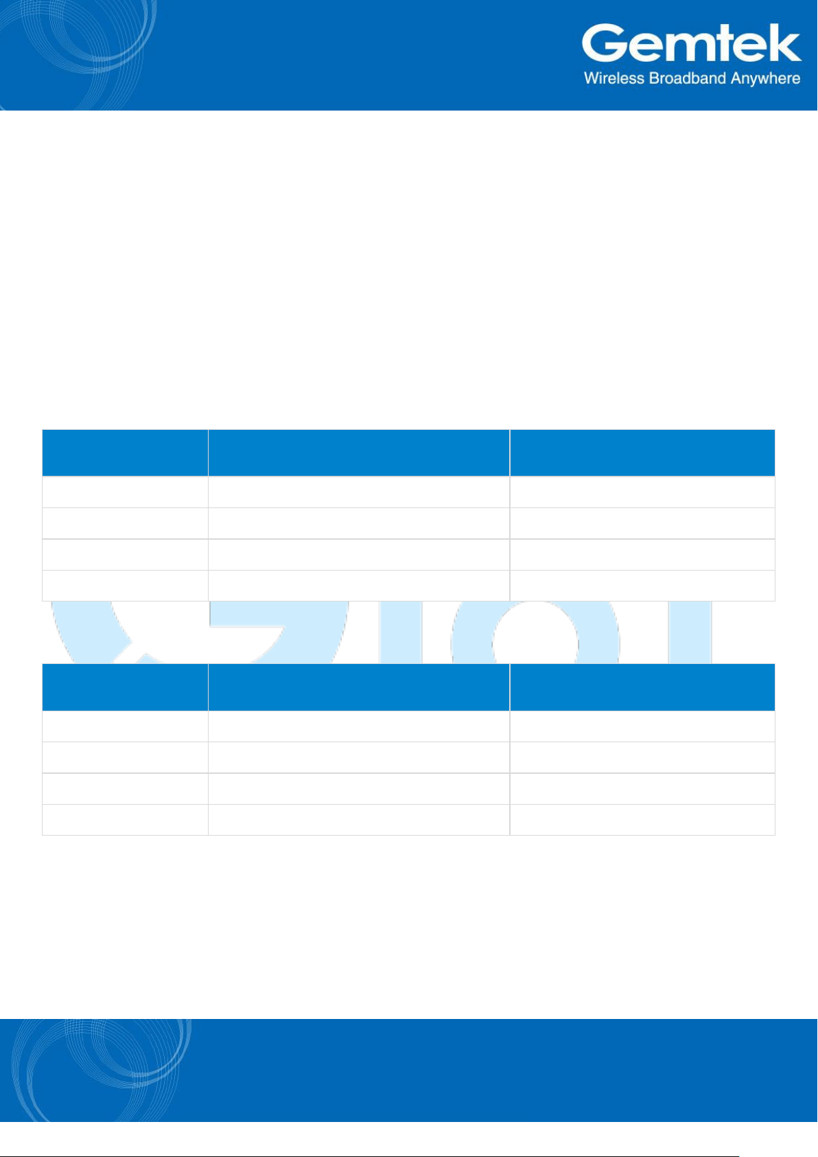
SF
Data rate (bit/sec)
Sensitivity (dBm)
7
5469
-130.0
8
3125
-132.5
9
1758
-135.0
10
977
-137.5
SF
Data rate (bit/sec)
Sensitivity (dBm)
7
5469
-125.0
8
3125
-128.0
9
1758
-131.0
10
977
-134.0
The GL6509 module is based on LoRa technology to provide low power long range
communication using spread spectrum. This provides very high receive sensitivity enabling
communication with high interference immunity.
Using LoRa modulation, depending on the spreading factor (SF), GL6509 can achieve system
receiver sensitivity of -137.5 dBm.
TABLE 1-1: RECEIVER SENSITIVITY OF SYSTEM WITH 125 KHz MODE(UPLINK WITH SX1257)
TABLE 1-2: RECEIVER SENSITIVITY OF MODULE WITH 125 KHz MODE(DOWNLINK)
Page 4
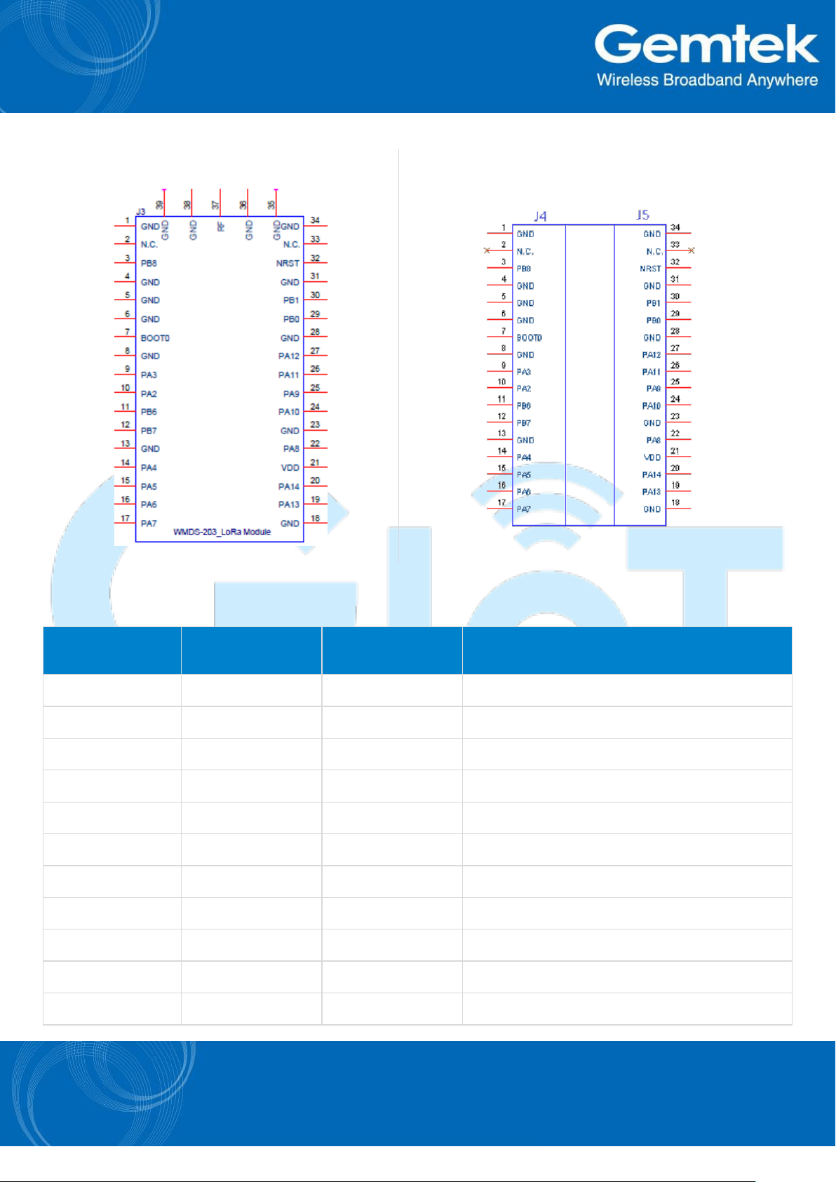
FIGURE 1-1: GL6509 SMT PIN DIAGRAM(Top View)
FIGURE 1-2: GL6509 PIN HEADER PIN DIAGRAM(Top
View)
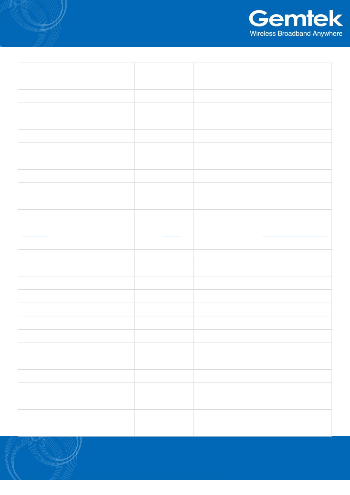
TABLE 1-2: SMT PIN DESCRIPTION
Pin
Name
Type
Description
1
GND
Power
System Ground
2
N.C.
---
Not Connected
3
PB8
Input/Output
GPIO_1
4
GND
Power
System Ground
5
GND
Power
System Ground
6
GND
Power
System Ground
7
BOOT0
Input
Reserved for debug. Not Connected.
8
GND
Power
System Ground
9
PA3
Input/Output
GPIO_2
10
PA2
Input/Output
GPIO_3
11
PB6
Input/Output
GPIO_4
Page 5
12
PB7
Input/Output
GPIO_5
13
GND
Power
System Ground
14
PA4
Input/Output
GPIO_6
15
PA5
Input/Output
GPIO_7
16
PA6
Input/Output
GPIO_8
17
PA7
Input/Output
GPIO_9
18
GND
Power
System Ground
19
PA13
Input / Output
SWDIO (Debug Port)
20
PA14
Input
SWCLK (Debug Port)
21
VDD
Power
Positive supply
22
PA8
Input/Output
GPIO_10
23
GND
Power
System Ground
24
PA10
Input
Communication USART1 Transmit (RX)
25
PA9
Output
Communication USART1 Receive (TX)
26
PA11
Input/Output
GPIO_11
27
PA12
Input/Output
GPIO_12
28
GND
Power
Supply Ground
29
PB0
Input/Output
GPIO_13
30
PB1
Input/Output
GPIO_14
31
GND
Power
System Ground
32
NRST
Input
MCU Reset
33
N.C.
---
Not Connected
34
GND
Power
Supply Ground
35
GND
Power
Supply Ground
36
GND
Power
Supply Ground
37
RF
RF Analog
RF RX/TX pin
38
GND
Power
Supply Ground
39
GND
Power
Supply Ground
Page 6

2 GENERAL SPECIFICATIONS
Specifications
Modulation Method
LoRa® Technology modulation
Maximum Over-the-Air Data Rate
5469 bps
RF connection
UFL Connector
Interface
UART (reserve for UART*1, I2C*1, SPI*1)
Sensitivity at 10 % BER
-137.5 dBm @ Lora Modulation, BW = 125K, SF = 10
Temperature
-40°C to + 85°C(Operating)
40°C to + 125°C(Storage)
Humidity
10% ~ 90%
non-condensing
Table 2-1 provides the general specifications for the module. Table 2-2, Table 2-3 and Table 2-4 provide
the electrical characteristics, current consumption and output power of Tx power setting.
TABLE 2-1: GENERAL SPECIFICATIONS
Page 7

Parameter
Min.
Typ.
Max.
Units
Supply Voltage, VDD
2.5
---
3.6
V
Voltage on any pin with respect to VSS (except VDD)
-0.3
---
VDD +
0.3
V
Output current sunk by any I/O and control pin
---
---
25
mA
Output current sourced by any I/O and control pin
---
---
-25
mA
Input low level voltage, VIL
---
---
0.3VDD
V
Input high level voltage, VIH
0.7VDD
---
---
V
Output low level voltage for an I/O pin, VOL
---
---
1.3
V
Output high level voltage for an I/O pin, VOH
VDD-1.3
---
---
V
RF Input Level
---
---
+10
dBm
Mode
Typical current at 3V (mA)
Standby
20
Receive
30
Deep Sleep
0.0043
TABLE 2-2: ELECTRICAL CHARACTERISTICS
TABLE 2-3: CURRENT CONSUMPTION
Page 8

Band
TX Power index
Output Power(dBm)
Current Consumption @
VDD = 3.3V(mA)
915 MHz
2
2.3
48
3
3.27
50
4
4.4
52
5
5.41
54
6
6.52
56
7
7.65
58
8
8.63
60
9
9.65
62
10
10.76
66
11
11.73
69
12
12.76
73
13
13.75
77
14
14.74
81
15
15.65
87
16
16.51
95
17
17.29
105
18
17.83
113
19
18.54
123
20
19.15
135
TABLE 2-4: OUTPUT POWER OF TX POWER SETTING (BW=125KHZ)
Page 9

3 TYPICAL HARDWARE CONNECTIONS
Specification
Description
Baud Rate
9600 bps
Data Length
8 bits
Parity Bit
No
Stop Bits
1 bit
Hardware Flow Control
No
Figure 3-1 shows the typical hardware connections where GL6509 is connected as a modem.
FIGURE 3-1: HARDWARE CONNECTIONS
3.1 INTERFACE TO HOST MCU
A typical application of GL6509 is to use the UART connection to communicate with a host controller. In
this application, the GL6509 is treated as a LoRa modem.
TABLE 3-1: DEFAULT UART SETTINGS
Page 10

3.2 GPIO AND INTERRUPT PINS
The GL6509 has 14 GPIO pins.
3.3 ANTENNA CONNECTIONS
There are two versions of antenna connectivity: one via the U.FL connector and the other via the SMT pin
(RF Pin 37).
3.4 POWER PIN
It is recommended that all the power related pins are connected.
3.5 BOOT PIN
This general purpose input pin is used to boot the GL6509 module. This is reserved for debug purpose. Not
Connected
.
3.6 RESET PIN
This input pin is for reset of the module’s MCU. Low active.
Page 11

4 PHYSICAL DIMENSIONS
Figures 4-1 and 4-2 show the physical dimensions for both the SMT and the PIN Header mounted versions.
Figure 4-3 shows the module PCB footprint, Figure 4-4 shows the module PIN Header type Pin Number.
FIGURE 4-1: GL6509 SMT DIMENSIONS
FIGURE 4-2: GL6509 PIN HEADER VERSION DIMENSIONS
Page 12

FIGURE 4-3: GL6509 SMT Type Recommend PCB Footprint.
FIGURE 4-4: GL6509 PIN Header Type Pin
Number (Bottom view).
Page 13

5 REGULATORY INFORMATION
5.1 NCC
第十二條→經型式認證合格之低率射頻電機,非經許,公司,商號或使用者均不得擅自變更頻率大
率或變更原設計之特性及能
第十四條→低率射頻電機之使用不得影響飛航安及擾合法通信;經發現有擾現象時,應立即停用,並
改善至無擾時方得繼續使用
前項合法通信,指依電信法規定作業之無線電通信 低率射頻電機須忍合法通信或工業科學及醫療用
電波輻射性電機設備之擾
1. 本模組於得認證後將依規定於模組本體標示審驗合格標籤
5.2 FCC
2. 系統廠商應於上標示本產品含射頻模組:
CCAFXXLPXXXXTX)字樣
Federal Communication Commission Interference Statement
This equipment has been tested and found to comply with the limits for a Class B digital device,
pursuant to Part 15 of the FCC Rules. These limits are designed to provide reasonable protection
against harmful interference in a residential installation. This equipment generates, uses and can
radiate radio frequency energy and, if not installed and used in accordance with the instructions,
may cause harmful interference to radio communications. However, there is no guarantee that
interference will not occur in a particular installation. If this equipment does cause harmful
interference to radio or television reception, which can be determined by turning the equipment off
and on, the user is encouraged to try to correct the interference by one of the following measures:
- Reorient or relocate the receiving antenna.
- Increase the separation between the equipment and receiver.
- Connect the equipment into an outlet on a circuit different from that
to which the receiver is connected.
Page 14

- Consult the dealer or an experienced radio/TV technician for help.
FCC Caution: Any changes or modifications not expressly approved by the party responsible for
compliance could void the user's authority to operate this equipment.
This device complies with Part 15 of the FCC Rules. Operation is subject to the following two
conditions: (1) This device may not cause harmful interference, and (2) this device must accept
any interference received, including interference that may cause undesired operation.
IMPORTANT NOTE:
Radiation Exposure Statement:
This equipment complies with FCC radiation exposure limits set forth for an uncontrolled
environment. This equipment should be installed and operated with minimum distance
20cm between the radiator & your body.
This transmitter must not be co-located or operating in conjunction with any other antenna or
transmitter.
Country Code selection feature to be disabled for products marketed to the US/CANADA
Operation of this device is restricted to indoor use only
Page 15

This device is intended only for OEM integrators under the following conditions:
1) The antenna must be installed such that 20 cm is maintained between the antenna and
users, and
2) The transmitter module may not be co-located with any other transmitter or antenna,
As long as 2 conditions above are met, further transmitter test will not be required. However, the
OEM integrator is still responsible for testing their end-product for any additional compliance
requirements required with this module installed
IMPORTANT NOTE
In the event that these conditions can not be met (for example certain laptop configurations or colocation with another transmitter), then the FCC authorization is no longer considered valid and
the FCC ID can not be used on the final product. In these circumstances, the OEM integrator will
be responsible for re-evaluating the end product (including the transmitter) and obtaining a
separate FCC authorization.
End Product Labeling
This transmitter module is authorized only for use in device where the antenna may be installed
such that 20 cm may be maintained between the antenna and users. The final end product must
be labeled in a visible area with the following: “Contains FCC ID: MXF-WMDS-203”.
Manual Information to the End User
The OEM integrator has to be aware not to provide information to the end user regarding how to
install or remove this RF module in the user’s manual of the end product which integrates this
module.
The end user manual shall include all required regulatory information/warning as show in this
manual.
Page 16

PRODUCT IDENTIFICATION SYSTEM
G L 6 5 0 9 _ A _ M _ U
GL6509: for Gemtek LoRa module model name
A: for AT Commands; M: for ModBus; P: Programming
M: SMT; P: Pin Header
A: Antenna; T: Trace; U: U.FL
 Loading...