

Page 1

LTE Cat6 TD-LTE CPE
Quick installation Guide
WLTMS-110-HGA / WLTMS-110
LTE Outdoor CPE
Connection Guide
Page 2

Contents
CONTENTS……………………………………………….….1
1. CONNECTORS ................................................ 2
2. LED INDICATORS .......................................... 3
3. INSTALLING LTE OUTDOOR CPE .................... 4
4. CONNECTING THE CABLES ............................ 5
5. WEB INTERFACE ........................................... 7
1
Page 3
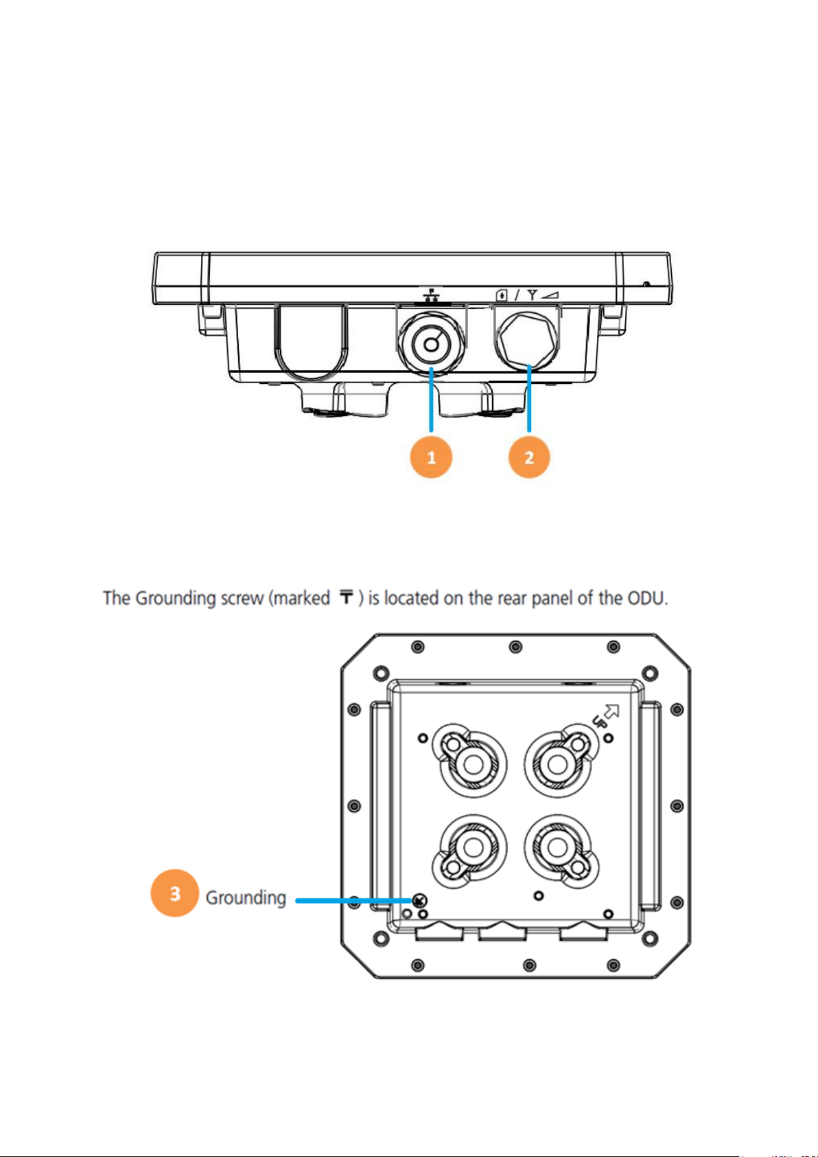
Connectors
1. One RJ-45 connector for connecting to the PoE adaptor.
2. LED indicator inside and SIM card slot for inserting SIM card.
3. A grounding screw on the rear panel.
2
Page 4

LED Name
Location
Color
LED Behavior
Status Indication
LED list
Main Power
Blue
ON
Power On
OFF
Power Off
Ethernet
Status
Yellow
Steady ON
Detect Ethernet
Device Connected
Blinking
N/A
OFF
No Ethernet action
SIM status
Green
Steady ON
SIM Detected
Blinking when
On-hook
PUK / PIN Code
OFF
No SIM Detected
LTE Status LED : Link Status
When CPE is power on, each LED
indicates each link status
LET 1
Red
Steady ON
SINR< 11dB
LTE 2
Red/
Yellow
Steady ON
11dB≦ SINR<
18dB
LTE 3
Red/
Yellow/
Green
Steady ON
SINR≧ 18dB
LED Indicators
3
Page 5

Installing LTE outdoor CPE
Selecting a Location: LTE Outdoor CPE should be pole-mounted
outdoors and aligned so its antenna faces the nearest LTE eNB. When
selecting a suitable location for the unit, consider these guidelines:
• Place LTE Outdoor CPE as high as possible to achieve the best
possible link quality.
• Place the LTE Outdoor CPE away from power and telephone lines.
• Avoid placing LTE Outdoor CPE too close to any metallic reflective
surfaces.
• Be sure to ground LTE Outdoor CPE with an appropriate grounding
wire (not included) by attaching it to the grounding screw on the unit
and to a good ground connection.
Mounting the ODU: Mount LTE Outdoor CPE on a 1”-4” pole using the
supplied kit, or the optional tilt accessory.
• Using the clamp
1. Thread the M10*100mm bolt through a spring washer, flat
washer and the bracket holes.
2. With the connector facing downward, attaches LTE Outdoor CPE
to a 1”-4” pole.
3. Attach the bracket to the other side of the pole.
4. Thread the M10*100mm bolts through both holes on either side,
and tighten the nuts.
4
Page 6

Connecting the Cables
Outdoor Connection: Connect a grounding cable between the Ground
terminal of the LTE outdoor CPE and a good ground connection.
Preparing and connecting the cable: Use only 5E 4x2x24# FTP (or
above) outdoor Shielded Patch Cable from an approved manufacturer.
1. Insert the RJ-45 cable:
Insert the Cat5 RJ-45 cable into the sealing gland base and connect it
to the RJ-45 connector at the bottom of the ODU, labeled. Make sure
that the connector is completely inserted and tightened.
((Suggest to use Cat 5E 4x2x24# F/STP outdoor Shielded Patch Cable))
((The total length of the Ethernet cables from the ODU to the IDU’s RJ-45
(WAN) PoE port. Must not exceed 100m))
2. Connect the cable
• Remove the sealing cable gland plug from the gland nut.
• Open the sealing gland nut and remove it. Don not disassembles
the gland base from the bracket.
5
Page 7

• Insert the cable into the sealing gland base and connect it to the
RJ-45 connector at the bottom of the CPE. Make sure the connector
is completely inserted and tightened.
• Insert the rubber bushing on the cable into the gland base.
• Tighten the gland nut. Use the dedicated tool for fastening the
sealing glands.
Indoor Connection
1. It is assumed that the RJ-45 is already connected to the LTE outdoor
CPE. Assemble an RJ-45 connector with a protective cover on the
other end of the LTE outdoor CPE cable.
2. Connect the other end of the RJ-45 cable to the PoE adaptor which
labeled “PoE”.
3. Connect RJ45 cable from PoE adaptor which label “LAN” to a
PC/NB/Hub/Switch.
6
Page 8

Mode:
LTE
Operator:
APN Name
Signal:
(More bar means better signal)
(Disconnect, no signal)
Web Interface
Please follow the steps below to configure your device through the web
interface:
Step1: Open the Web browser (Internet Explorer) and enter the default IP
address of the ODU CPE, which is : http://192.168.15.1
Step2: Enter ODU guest login username/password to access the web
management interface. The default username/password is admin /
admin .
Web management interface
Step3: The page shown here gets displayed in your browser after login; you
can now configure the device settings.
GUI Interface
7
Page 9

Federal Communication Commission Interference Statement
This equipment has been tested and found to comply with the limits for a Class B
digital device, pursuant to Part 15 of the FCC Rules. These limits are designed to
provide reasonable protection against harmful interference in a residential installation.
This equipment generates, uses and can radiate radio frequency energy and, if not
installed and used in accordance with the instructions, may cause harmful
interference to radio communications. However, there is no guarantee that
interference will not occur in a particular installation. If this equipment does cause
harmful interference to radio or television reception, which can be determined by
turning the equipment off and on, the user is encouraged to try to correct the
interference by one of the following measures:
- Reorient or relocate the receiving antenna.
- Increase the separation between the equipment and receiver.
- Connect the equipment into an outlet on a circuit different from that to which the
receiver is connected.
- Consult the dealer or an experienced radio/TV technician for help.
FCC Caution: Any changes or modifications not expressly approved by the party
responsible for compliance could void the user's authority to operate this equipment.
This device complies with Part 15 of the FCC Rules. Operation is subject to the
following two conditions: (1) This device may not cause harmful interference, and (2)
this device must accept any interference received, including interference that may
cause undesired operation.
FCC Caution: Any changes or modifications not expressly approved by the party
responsible for compliance could void the user's authority to operate this equipment.
IMPORTANT NOTE:
FCC Radiation Exposure Statement:
This equipment complies with FCC radiation exposure limits set forth for an
uncontrolled environment. This equipment should be installed and operated with
minimum distance 34 cm between the radiator & your body.
This transmitter must not be co-located or operating in conjunction with any other
antenna or transmitter.
8
Page 10

Professional installation instruction
Please be advised that due to the unique function supplied by this product, the device
is intended for use with our interactive entertainment software and licensed third-party
only. The product will be distributed through controlled distribution channel and
installed by trained professional and will not be sold directly to the general public
through retail store.
1. Installation personal
This product is designed for specific application and needs to be installed by a
qualified personal who has RF and related rule knowledge. The general user
shall not attempt to install or change the setting.
2. Installation location
The product shall be installed at a location where the radiating antenna can be
kept 34 cm from nearby person in normal operation condition to meet
regulatory RF exposure requirement.
3. External antenna
Use only the antennas which have been approved by Gemtek, BLiNQ. The
non-approved antenna(s) may produce unwanted spurious or excessive RF
transmitting power which may lead to the violation of FCC limit and is
prohibited.
4. Installation procedure
Please refer to user’s manual for the detail.
5. Warning
Please carefully select the installation position and make sure that the final
output power does not exceed the limit set force in relevant rules. The violation
of the rule could lead to serious federal penalty.
9
 Loading...