

Page 1
Wirel
LAN
Use
d
age
ess
User Manual
WL-211
PC Card
Version 1.0 – Februar y 1999
r manual WL-211 PC Car
P
1
Page 2

Wirel
LAN
ess
Federal Communication Commission Interference Statement
The information in this document is subject to change without notice and should not be construed as a
commitment by GemTek Technology Co., Ltd. GemTek Technology assumes no responsibility for any
error that may appear in this doc ument .
GemTek is a r egist er ed tr ademark of GemTek Technolog y Co., Ltd .
The f ollowing are t r ademark ed company and their nam es and p r oducts are used in t his guid e for
information pu rp os e onl y.
PC Card is a trademark of PCMCIA
Windows is a tr ademark of Micr osoft Cor por at ion.
All the oth er tradem ar k s and register ed tradem arks are the propert y of their respect ive own er s .
INFORMATION TO USER
FCC REQUIREME NT S
This device comp lies wit h p ar t 15 of th e FCC Rules .
Operation is subject to th e following two cond itions:
(1) This device may not cause harmful interference, and
(2) This device must accept an y interference received , including interference that may cause
undesired operation.
NOTE: This equipme nt has been tested and fo und to comply with the limits f or a Class B digital device, pursuant to Par t 15
of the FCC Rules. These limits are des igned to pr ovide reasonable prot ection against harmf ul interference in a r esidential
installation. This equipment generates, uses and can radiate radio frequency energy and, if not installed and used in
accordance wit h the instructions, may cause harmful interf er ence to radio communications. However, there is no guarantee
that interference will not occur in a particular insta llation. If this equipme nt does cause harmful interference to radio or
television receptio n, w hich can be determined by turning the equipment off and on, t he user is encouraged t o tr y to cor r ect
the interference by one or more of the following measures:
Reorient or relocat e the receiving ante nna.
Increase the separatio n betw een the equipme nt and receiver.
Connect the equipment into an outlet on a circuit different from that to which
the receiver is connected. c onsult the dealer or an experie nced radio/TV
technician for help.
FCC Caution : To assu r e c ontinued complian c e, (example - use only shielded interfac e c ables when
con necting to computer or peripheral devices) . Any chang es or m odific ations not express ly approved
by the party respons ible for c om plian c e c ould void t he user's authorit y to operate this equ ipment .
Responsible Party: Synnex Co;LTD.
3797 Spinn ak er Ct.
Fremont,CA 9453
Jim Nguyen
Fax No: 510-668-360 2
Telephone No: 510-6 56- 3333
Email Address : jimn@synnex.com
-
Page 3

Wirel
LAN
Use
d
age 3
ess
FCC Radiation Exposure Statement
This equipment c omp lies wit h FCC rad iation exp os ure limits s et forth f or an uncont r olled environmen t.
This equipment sh ould be in s talled and op er ated with the minimum dist ance bet ween your bod y and
the antenn a as s hown in the table below:
Int egrated PCMCIA An tenna 20cm (7 inch es)
r manual WL-211 PC Car
P
Page 4

Wirel
LAN
ess
1. Contents
1 Contents ……………………………………………………………………………………………… 3
2 Introdu ction…………………………………………………………………………………………… 4
3 Wireless LAN Basics………………………………………………………………………………….6
4.
Instal lation for Wind ows 95 (OSR2)/98………………….………………………………………….7
4.1 Installation Overview……………………………….……………………………………………8
4.2. Installation Procedure of WL-211 PC Card…………………………………………….……..9
5. Configuration Util it …………………………………..………………………………………………11
6. Troubleshooting …….……………………………………………………………….………………18
7. Technical specifications of WL-211..………………………………………….……………………19
-
Page 5

Wirel
LAN
Use
d
age 5
ess
2. Introduction
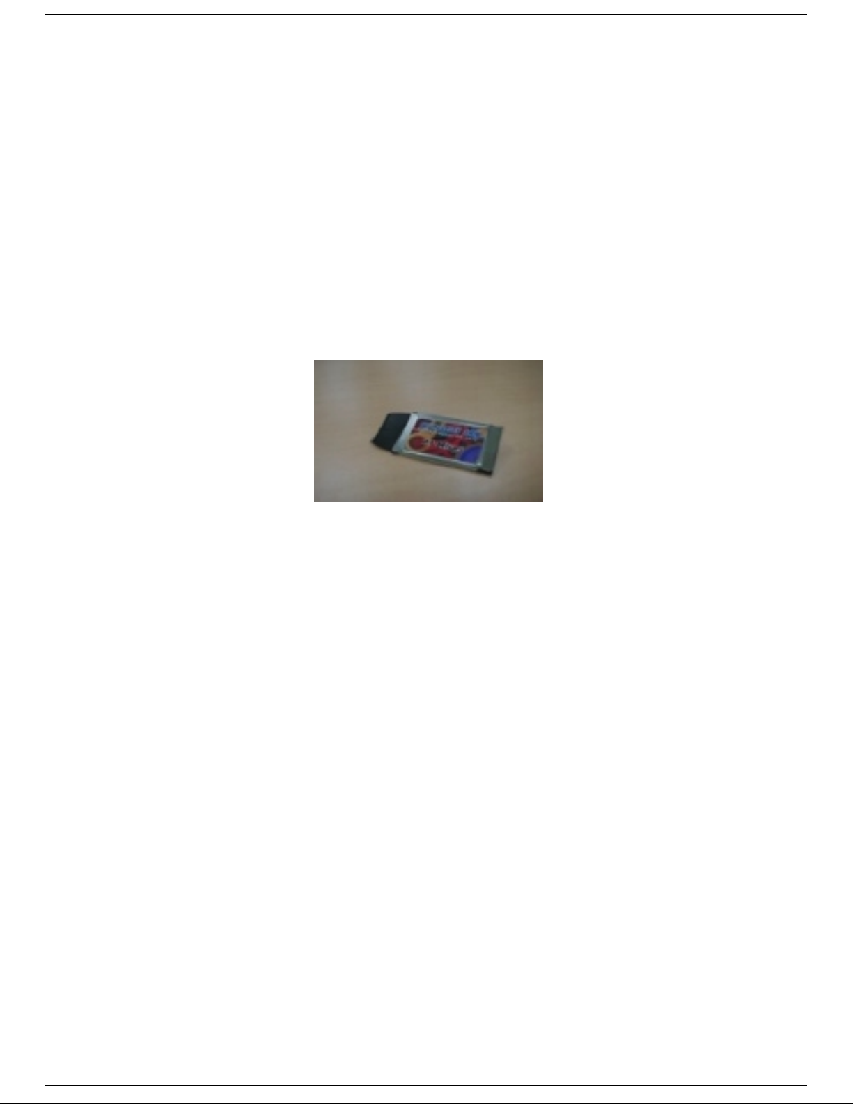
Than k you f or purchasin g your Wir eless LAN, W L-211 PC Card . This manu al will assist you with th e
installation procedure.
The packag e y ou have rece ived shoul d c ontain the following it em s :
• WL-211 P C Car d
• User manual
• Diskette containing Wireless LAN Management utility and drivers
Note: if anything is m is s ing, pleas e c ontac t you r ven dor
The diskette contains the drivers and the program
Gtutil
that is u sed for man aging the W L-211 Card
and establishing the wireless c onn ec tion with your Local Area Network.
r manual WL-211 PC Car
P
Page 6

Wirel
LAN
ess
3. Wireless LAN Basics
Wireless LAN (Local Area Networks) systems offer a great number of advant ages over a traditional,
wired system. Wireless LANs (WLANs) are more fl exible, easier to setup and manage and often more
cost effect ive t han their wired equivalence.
Using radio frequency (RF) technology, WLANs transmit and receive data over the air, minimizing the
need for wired connections. Thus, WLANs combine data connectivity with user mobility, and, through
simplified configur ation, enable m ovab le LANs.
With wireless LANs, users can access shared information without looking for a place to plug in and
net work m anag ers can set up or augm ent net works wit h out in stall ing or moving wires. Wir eles s LANs
off er the foll owing pr oduct ivity , con ven ience and c os t advantages over tr aditional wir ed n etworks:
• Mobility - Wireless LAN systems can provide LAN users with access to real-time information
anywhere in their organization. This mobility supports productivity and service opportunities not
possible with wired networks.
• Inst al lat ion Speed and Sim plic ity - Inst all ing a wirel ess LAN system can b e fast and easy and can
elim inate t he need to pull c able thr ough walls and ceilings.
• Installation Flexibility - Wirel es s techn ology all ows the network t o go where wires c ann ot go.
• Reduced Cost-of-Ownership - While the initial investment required for wireless LAN hardware
mig ht be high er th an the cost of wired LAN har dware, over all installat ion expen ses and l ife-cy cl e
costs will be significantly lower. Long-term cost benefits are greatest in dynamic environments
requiring frequent moves, adds, and changes.
• Scalability - Wireless LAN systems can be configured in a variety of top ologies to meet the needs
of sp ecif ic app l ication s and inst all ation s. Con figu rat ions ar e eas ily chang ed and rang e from p eerto-p eer n et works s uit abl e for a smal l nu mber of u ser s to ful l in f rast ructu re n etwork s of thou sand s
of users th at allows r oaming over a b r oad area.
-
Page 7

Wirel
LAN
Use
d
age
ess
WIN 2000
WIN 98 Notebook
For PC Card
NT Workstat ion
WINNT SERVER
A P-1 100
Hub
A P-550
WX-1150
A ccess Point
WinCE
r manual WL-211 PC Car
P
7
Page 8

Wirel
LAN
ess
4. Installation for Windows 95 (OSR2)/98
The following section will assist you to in install ing wirel ess LAN Adapter successfully. You will first
install software (driver) and then insert the WL-211 wireless LAN card, and finally set the network
pr oper ties t o accom mod ate res our ce sh aring and select the t ype of wir eles s n etwork t h at you wish t o
ins tall . Th e WL-211 can easil y b e in stall ed and used, with out both erin g to conn ect cabl es for keep ing
your computer to use network resources, as in case of wired LAN.
-
Page 9

Wirel
LAN
Use
d
age 9
ess
4.1. Installation Overview
Here are some st eps you will per form in establishing you r wireless network c onnect ion:
! Install the Acess Point at first. AP is needed in case of Infrastructure network mode.
! Install th e s oftware using the In s tallation Disket te.
! Install th e Wirel es s LAN Card (WL- 211).
! Instal l the n et work prot ocol (s) requ ired to com mun icate on y our network . Most lik ely you will need
the TCP/IP protoc ol.
r manual WL-211 PC Car
P
Page 10

Wirel
LAN
ess
4.2. Installation Procedure of WL-211 PC Card
Note: Do not insert the
of your
PCMCIA WLAN
PCMCIA
card
Pl eas e follow the f ollowing s teps on e by one in order to ins tall the
1. Power on you r c omput er and all ow
2. Be sure that there is no
card until you are asked to do so, failure of which may result in unsuccessful installation
PCMCIA
Windo ws 95 (OSR2)/ 98
adapter ins er ted yet.
PCMCIA
to load fully.
card successfully.
3. Ins er t the given Installation Dis k ette and then click on the A:\disk1\ s etup.exe.
4. Accep t the license agreem ent.
5. Give the path of the destination fol der. To set the path of you r choice click on
Next
.
6. It takes a few seconds f or copying the utility files and then click on
Finish
Browse
and th en click
to complete the
installation.
7. In s er t the WL-211F car d into PCMCIA slot , windows will then prompt the required d r iver
8. locate the driver path Ex. A:\ and install the driver
9. restar t th e PC and Click on the Cont rol Panel and then on PC Card . Ch eck whet her it has P CMCIA
card in on e of the sock ets or n ot. If you find Gem tek IEE 802.11PC Card in one of th e socket s, it
mean s the card is detected pr oper ly.
10. Ch eck for th e
usin g the mouse. S elect th e Device m anag er an d th en Net work Ad apt ers. If you f ind the
GEMTEK 11Mbps Wireless PCMCIA LAN Card
by right clicking on My Compu ter
Yellow (?)
sign on the adapter, it shows the installation is not successful. Select the adapter and click on
Remove
. Restart your computer after uninstalling the driver to make the changes effective. And
refer to manual.
11. Right click on the
12. Select
Properties
Configuration, Identification
13. Click on the
box appears. Clic k on the
14. Select Net work P rotoc ols box ap pear s. F rom th e list of m anufact u res, cl ick on
list of network protocols list, select
Network Neighborhood
us ing the mou s e.
from the p op up menu. The net work b ox app ears and you s ee th ree m ain t abl es:
Access Con t rol
Configuration
, and
tab and then cl ick on the
Protocol
the click th e
Add
.
Add
butt on.
button . Selec t Network Com ponent Type
Microsoft
NetBEUI
, then click OK.
. Fr om t he
15. The
NetBEUI
protocol is now installed. After clicking on OK return back to Network Component
Type box.
16. Repeat the step 15 and 16 to add IPX/S P X p r otocol .
17. Repeat the step 15 and 16 to add TCP/IP pr otocol .
-
Page 11

Wirel
LAN
Use
d
age
ess
18. Click on the
TCP/IP
option for sett ing the IP ad dress for your computer. You can select either
Static
DHCP
or
setting. If you use the static IP setup then enter the IP value,
Domain/ Workgroup
name, and
Gateway
Address values. After setting these parameter
Subnet
masking ,
appropriately, click OK to return to Network Component Type and you can select the
Printer Sharing
option s as well as the
Access
to your computer bu other users connected to that
network b y s etting th e c om puter sh ar ing op tions. Click on OK.
19. Screen message
do want to restart your Computer
will pop up. Select
Yes
. It will shut down your
comput er and will restart.
Important: Restart your computer to make the changes effective before you reinstall the
driver.
DNS
File and
,
Proceed to chapter 5 for the exp lan ation of th e Configurat ion Utility.
r manual WL-211 PC Car
P
11
Page 12

Wirel
LAN
ess
5. Configuration Utility
GemTek Inc P C Card Wir eless LAN adap ter (G emTek NIC) u ses his own man agement s oftware. All
functions controlled by user are provided by this application. Usually this application starts
automatically, Use Start, Programs, GemTek Wireless LAN to start the Manager application.
A new icon - sh ould ap pear in you r Icon tr ay. If the icon is marked with a red “X”, it means th at
GemTek NIC configuration is invalid or incomplete. Sometimes icon can be colored in red. This can
happen when driver is in Pseu do BSS mode, and the radio channel, which is used for commun ication
is defined incorrectly.
Figure 1 Icon tray with a new icon
Figure 2: Error Icon
Double cl ic k ing on that icon will show you the s c r een as s hown below.
Figure 3 Manage ment win dow with “St at us” t ab open
User can navig ate throug h “ s heets ” , by click ing or tapp ing them with a styl us. “O K ” bu tt on will minimiz e
wind ow, and “Exit” (or X butt on) will cl ose appl ication. Here we explain the u se an d meanin gs of the
var ious screen messages.
-
Page 13

Wirel
LAN
Use
d
age 13
ess
The f ir s t three fields show your wireles s networ k c ard state.
Link status
– indicates lin k acces ibil ity. There are several val ues, that can be shown in this part of the
window:
Connect ed - BS SID= …
– normal flow of op eration in In fras truc ture m ode. The P C is conn ect ed to
access point.
No status…
BSSID
is shown in th e form of h ex d igits. Networking is avail abl e.
- the manager is retrieving information from the driver. If this text box value stays more
than several secon ds, it means th at there ar e no acces s points or other works tations (if
communicating in AdHoc mode), or that the GemTek NIC card is plugged out of PC.
Scanni ng f or access po int
– driver scans wireless n etwork sear c hin g for available ac c es s poin t
in Infrastructure mode.
Disabled or disconn ect ed
- . If this text box value stays more than several second s, it means that
there are no access points or other workstations (if communicating in Pseudo BSS mode), or
that the GemTek NIC card is plugged out of PC.
Undefined
– means critical driver error. This error is usually caused by h ardware misconfiguration
(for exampl e th e card with sim ilar ch ipset in ser ted in PC card b ay, b ut n ot ful ly comp atibl e with
GemTek NIC).
Input bytes/sec
– sh ows the incoming (received ) data s peed , th e progres s b ar below, m eans rec eiver
load.
Outp ut bytes/sec
– sh ows the out going ( s ent) d ata s peed, the prog r es s bar below, s hows transmitter
load.
Signal strength :
bar sh ows signal st rength level . The h igher blu e bar is, the mor e powerful is radio
signal received by Gemtek PC card. This indicator helps to find the most comfortable
antenna/ wor k s tation pos ition for qual ity networ k operat ion.
Link quality:
The meas ured signal level g ives t he overall Link Qu ality and Connect ion Status.
r manual WL-211 PC Car
P
Page 14

Wirel
LAN
ess
“C
ONFIGURATION
” tab
You can change the c onfigur ation by cl ic k ing on the
Change Configuration.
Change Configur ation, you see t he scr een given below.
When you click on the
Figure 4 Manage ment win dow with "C
Five ch angeabl e fields in this field show desired GemTek NIC con figurat ion.
ONFIGURATION
" tab open
The f ields are foll owing:
Station ESS ID
Exten ded S ervice Set Iden tifier ( Wireles s Network Ident ifier) is th e group name that
will be shared b y every memb er of your wireless network. You will only be able to connect with an
Access P oint
Network mode
Pseudo BSS
•
"cel l" is sup ported f or each dif ferent
wi t ho ut the use of a n
Infrastructure
•
, which has the same
sh ows one of t hese network m odes:
-this is the 802. 11 p eer-t o-p eer mod e of op erat ion . In
Access Point
This mode of oper ation req uires the pres ence of an 802. 11
ESS ID
.
ESS ID
.
Ad Ho c
only one wirel ess
. All communication is done from Client to Client
Access P oint
. All
communication is done via the
Access P oi nt
, which relays p ackets to oth er wireless Clients in
the BSS (Basic Service Set) as well as to nodes on a wired network such as Ethernet.
-
Page 15

Wirel
LAN
Use
d
age 15
ess
Encapsulation
None or Encapsulated
•
Header , and puts it int o an 802.11 frame. This s ettin g is here f or compatib ility with some old er
802.11 implem entations and should not normally be us ed.
RFC1042
•
RFC1042. This mode will also convert any RFC1042 SNAP header frames to DIX Ethernet
frames before transmission to the Ethernet interface.
802.1h
•
mod e does not con vert RF C104 2 SN AP head er f rames t o DIX Eth ern et b efore t ransmis sion to
the Ethernet interfac e
It is required to select encapsulation mode corresponding to the one your access point or other
workst ation s u se. If th e enc apsul ation mod e is incor rect , th e PC will join to acc ess p oin t or will
be s een by other wor k s tations, but network operation will not work.
shows one of two different network packet forming modes
This setting takes the entire Ethernet frame, including the Ethernet
where the DIX Ethernet frames are converted using SNAP header based on
wher e the DIX Eth ern et fram es are t unn eled using a full s elec tive tran sl at ion tabl e. Th is
Channel
– sh ows rad io chann el numb er used for n etwork ing. Only Access Poin ts and Ad Hoc n od es
can create a BSS therefore this p arameters is not active if Mode is Infrastructure. Infrastructure Client
nodes will always go the same channel as their AP. Please see the table for the requirements of
different countries and the channel frequency.
TX Rate:
The transmission rate at which the data packets are transmitted by the client or AP. You can
set this to Aut o s elect I or 2Mbps, Fixed 1 Mbps, Fix ed 2 Mbps, Fi xed 5.5 Mbps, Fi xed 11 or Full Auto
(I to 11 Mbps ) .
Important:
cause the unde sired
You must know the TX Rate that your AP can support. Failure to which may
results.
r manual WL-211 PC Car
P
Page 16

Wirel
LAN
ess
“E
NCRYPTION
” tab
Figure 5 Management window with “Encrypt io n” t ab open
You may desire an additional measure of security on your wireless network, which can be
achieved by using WEP (Wired Equivalent Privacy) encryption. WEP encrypts each frame
transmit ted from the rad io us ing on e of the Key s entered from this p anel.
Wh en an enc rypt ed fram e is recei ved it wil l only be accep ted if it dec rypt s corr ectly . This wil l onl y
happen if th e r ec eiv er has t he WE P Key used by the trans m itter.
This panel allows the entry of four keys, which can then be written to the driver and registry. Each
key must consist of hex digits, it means that only digit 0-9 and letters A-F are valid entries. If
ent ered incorrec tly program will not write keys t o a driver.
Key 1 – Key 4
Write :
This button updates the driver with the four keys displayed in Key1 t hrough Key4. The keys
: These four fields must be used to enter the keys.
are al s o wr itten to the r egist r y for perman ent stor age.
Clear :
over.
This bu tton clear s all the b ytes in the fou r key s, us eful wh en enter ing and you wish t o st art
-
Page 17

Wirel
LAN
Use
d
age
ess
Default Key :
This p op-up field defines one of the four keys wh ich will be used by the driver to
encrypt frames it will be transmitting. This field does not affect decryption, as the driver can
decrypt any frame t hat it rec eives which was encry pted with one of the four keys.
Enable :
This checkb ox enab les or dis ables enc ryption operation . When it is c hecked, encryp tion
is enab led, and wh en unch eck ed – enc rypt ion is disabl ed. Th e corres pon d ing act ion is writt en to a
dr iver imm ediately.
r manual WL-211 PC Car
P
17
Page 18

Wirel
LAN
ess
“A
BOUT
” tab
Figure 6 Management window with "A
BOUT
" tab open
About tab shows a software version. Users must use this version number when reporting their
pr oblems to tech support .
-
Page 19

Wirel
LAN
Use
d
age 19
ess
6. Troubles hooting
To make th e install ation of Wir eless LAN Car d more u sers fr iendly, we h ave sugg ested foll owing the
installation steps one by one as listed in the section 4 and section 5. Still you encounter some
pr oblems while ins talling the WLAN Car d or you wan t t o c onfirm whether your card is install ed properly
or n ot, we have list ed th e p rocedu re f or check ing th e various comp on ent s aft er you have inst al led th e
card. In first part of
Troubleshooting,
we have suggested the users to check the various properties of
th e card t o check the p rop er inst all ation . In sec ond s ection, we h ave list ed th e various p robl ems th at
you may encoun ter durin g the in stallat ion and have also l isted the possib le solu tion. Chec k the first
par t to guess the probabl e r eas on of unsu c c es s ful ins tallation.
Procedure to Check the Various Properties of Card after Installation under Windows 95
(OSR2)/98:
Pl ease ch eck th e foll owin g s if you encoun ter s ome p robl em while in stall ing th e P CMCIA card or you r
PCMCIA card is non-functional.
1. Clic k on the
of t he socket s or not. If you f ind
Control Panel
and then on
GemTek IEEE 802.11 PC CARDd
means the card is detected properly. If you see the
PC Card.
Check wheth er it has
in one of the sockets, it
Yellow
sign of Question-mark (?), the
PCMCIA
card in one
resources are conf licting.
2. Righ t cl ick on
on the
Network Adapter.
My Computer
successfully. If you see the
and th e select
You will find
Yellow
sign the res our ces are c onfl ict ing. Click on PCMCIA Car d
Properties.
Select the
Device Manager
GemTek IEEE 802.11 PC CARD
if it is installed
and then on PCMC IA Card Ser v ice, you can s ee the status of P CMCIA card. If ther e are yell ow
sip either on adapter or P CMCIA card , pleas e c heck the followings.
i) Check if your Notebook supports
ii) Check if y our Not ebook has a f ree
3.3V
IRQ.
Card.
If not, make an IRQ free by assigning
the same IRQ to some devices, for example COM 1, COM 2 can be assigned same
IRQ values.
iii) Ch ec k that you have ins er ted the r ight card and have in s talled the proper driver.
and cl ick
r manual WL-211 PC Car
P
Page 20

Wirel
LAN
ess
7. Technical specifications of WL-211
Hardware compatibility
− IBM-compatibl e c om puter with a PC Card Type II
Driver support
NDIS 3.1
− Win dows 95 O S R2
− Windows 98
− Windows NT 4 and higher
− Linux
− WinCE(x86,SH4,MIPS)
Standards supported
− IEEE 802.11 st and ar d for Wir eless LAN
− All major networking standards (including TCP/IP, IPX)
Environmental
Operating temperature (am bient) :
− -10°C t o 50°C (O perating ),- 20 to 70°C (S torin g)
− Max . Humidity:95% Non-condensing
Power specificati ons
Operating v oltage:
− +5 V ,+3.3V DC ±5%
− Nominal Temp Range: 17 dBm
− Extended Temp Range: 14 dBm min.
− Transmit Power, 2.7v to 3v: 14 dBm min.
Radi o speci f ications
Range:
− per c ell ind oor s approx. 35-100 met er s or m or e
− per c ell outdoors up to 100-300 met er s
Frequenc y r ange:
− 2.4-2. 4835 GHz , dir ec t sequ ence spr ead spectru m
Number of Channels:
− Europe: 13 (3 non-overlapping)
− US: 11 (3 non - overlapping )
− France: 4 ( 1 non-overl app ing)
Antenna system:
-
Page 21

Wirel
LAN
Use
d
age
ess
− Internal patch antenna supporting diversity.
Mobility:
− Seamless roaming across cell boundaries with handover
Specific f eat ures
Support ed bit rates :
− 11 Mbps
− 5.5 Mbps
− 1 Mbps
− 2 Mbps
Data encr y ption:
− 40 bit WEP Enc r yp tion, 128-bit k ey leng th optional
Utility Software:
− Link Config™ User s etup & diag nostic s tool
Key Management :
− Automatic Dynamic Key Allocation (ADKA) through public key
Physical Dimensio ns
− Extended type-II PC Card 110 x 54 x 6 mm
− Weight 3
r manual WL-211 PC Car
P
21
Page 22

Wirel
LAN
ess
-
 Loading...