

Page 1
Clear Modem Series G
User Guide
Model: WIXB-175
Manual Version: 1.3
Manual Date: July. 16 2009
Page 1 of 21
Page 2
Overview
Thank you for purchasing the Clearwire CPE Indoor (WIXB-175) desktop device. The Desktop
CPE allows you to connect to the wireless world easily and seamlessly without complicated
installation and setup procedures. In addition it offers you the ability to make Voice over
Internet Protocol (VoIP) calls.
The Desktop CPE indoor device provides the user:
Convenience — with easy plug and play functionality.
Performance — High gain antennas supply diversity technology. Best in Class range and
indoor penetration.
Control — remote management capability allows easy detection and authentication once
the unit is setup.
VoIP - One RJ11 port allow for Voice over IP calls using your CPE.
Powerful Features in a Single Unit
The CPE device provides the following features:
WiMAX Authentication
WAN DHCP Client
LAN DHCP Server
Home Gateway Functions
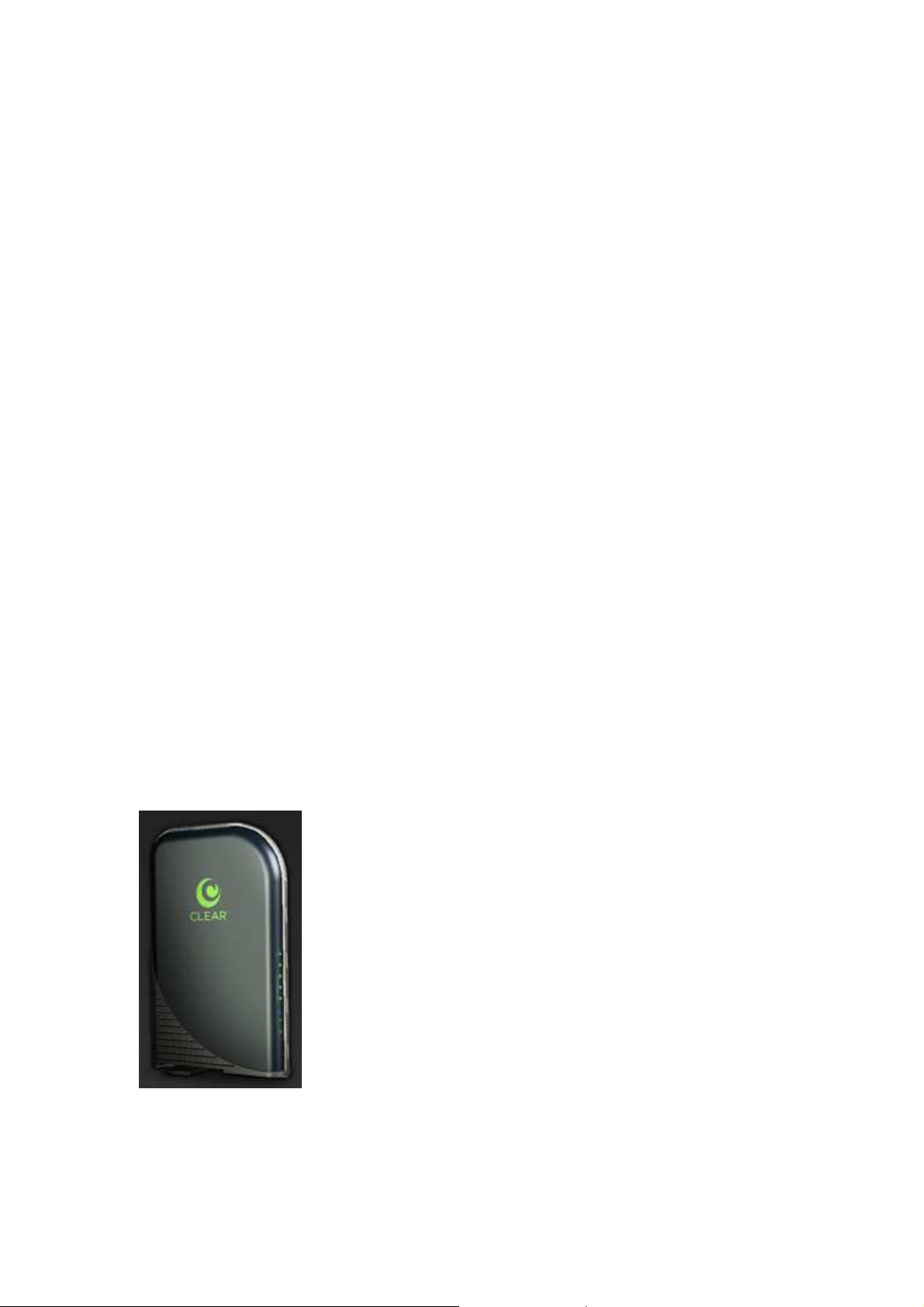
Front of CPE
The Front of the CPE units contains LED Link/Activity indicators. The LEDs provide the status
of the unit and signal strength indicators for easy adjustment during setup.
Front of Unit
LED Indicator Interface
The Power LED shall be Blue and the other LEDs shall be Green.
Page 2 of 21
Page 3

Power Status
The Power LED shall be on when the device is plugged in and has power.
Ethernet Status
The Ethernet LED should be on when the LAN Ethernet has been established and activity has
been detected.
Signal Strength
Once the device has registered on the network, the Signal Strength LEDs should be on
depending on different strength. Only one Signal Strength LED lit represents low signal
detected and all five Signal Strength LED lit presents high signal detected.
Back Panel Ports Description
Power AC Power Connector
Phone Line RJ-11 port for use with VoIP.
Ethernet Port
Reset button
Note: Hardware Reset Button (A paper clip is recommended for accessing this button). Before
resetting the CPE, ensure the power LED is ON. Hardware Reset Button will cause
PASSWORD, DEVICE NAME and LAN IP to be restored to default. If you would like to reset to
default as ex-factory setting, please do it via Basic/Restore Factory Settings.
Operating Information
Operating temperature for this unit is 0℃-40℃ (32-104F).
Installation
Overview
To install the Desktop CPE Series, you need to review the following sections:
Before You Begin
Easy Setup
Before You Begin
Before you begin installation, check that you have received the following items with your
Desktop CPE:
In the box with your CPE you should have:
Item Description
Power Adapter Power adapter connects the Clear Modem to an AC electrical outlet.
Page 3 of 21
Page 4

Ethernet Cable The Ethernet cable connects the Internet port on your Clear Modem to
your PC or laptop computer.
Clear Modem
Quick Start Guide Provides quick installation instructions for getting your Desktop CPE up
and running.
Welcome Letter A brief introduction of the stuff inside the packaging and customer
service contact window.
Regulatory letter The FCC regulatory statement for this Clear Modem
In addition, you will also need:
A computer
An RJ-11 telephone cable (optional, if you would like to use VoIP function).
Easy Setup
The CPE is easily set up in your home. Basic installation equipments needed are the power
adapter, Ethernet cable and a PC or laptop computer and the CPE device. If you want to use
the VoIP functionality, you will also need an RJ-11 phone cable and a telephone [external ATA
is needed].
Perform the following tasks before powering up the unit:
Stand the Clear Modem on a flat surface.
Plug the power adapter into the power connector on the back of the unit.
Plug the AC power cord into an AC outlet. The unit will turn on.
Plug one end of the Ethernet cable into the Ethernet connector on the back of the unit.
Plug the other end of the Ethernet cable into the Ethernet connector of your computer.
To use VoIP functionality of the phone, plug one end of the phone line into the activated
phone connector on the back of the unit. Phone line activation is dependent upon your
service contract.
Plug the other end of the phone line into the phone line connector of your telephone.
Page 4 of 21
Page 5
Procedure to Log into the CPE
Before you Begin Configuration, some settings on your computer must be verified or changed
to ensure that your computer configuration can support the Desktop CPE.
Verify that the IP addresses and DNS settings are automatically generated in your Local Area
connection of your Internet Protocol (TCP/IP) properties. Refer to the chapter titled
"Configuring TCP/IP" for information on how to do this.
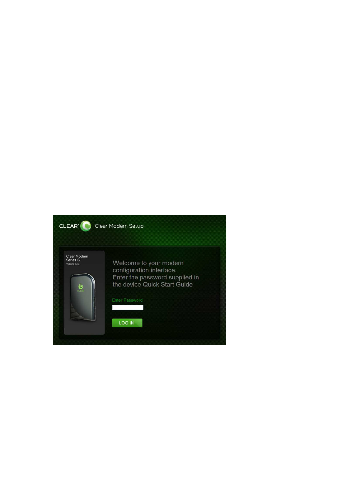
Logging In to the CPE
Use the following procedure to log into the Desktop CPE.
1. On a computer that is connected to the Clear Modem Series G, open a web browser.
2. In the Address or Location field, type http://192.168.15.1 and press ENTER to display the
login screen.
Login Screen
3. In the Password field, type the password (default is CLEAR123).
4. Click Login.
Page 5 of 21
Page 6
Basic Menu
The Basic menu provides the following tabs:
Password
Time Zone
Device Name
Reset Factory Settings
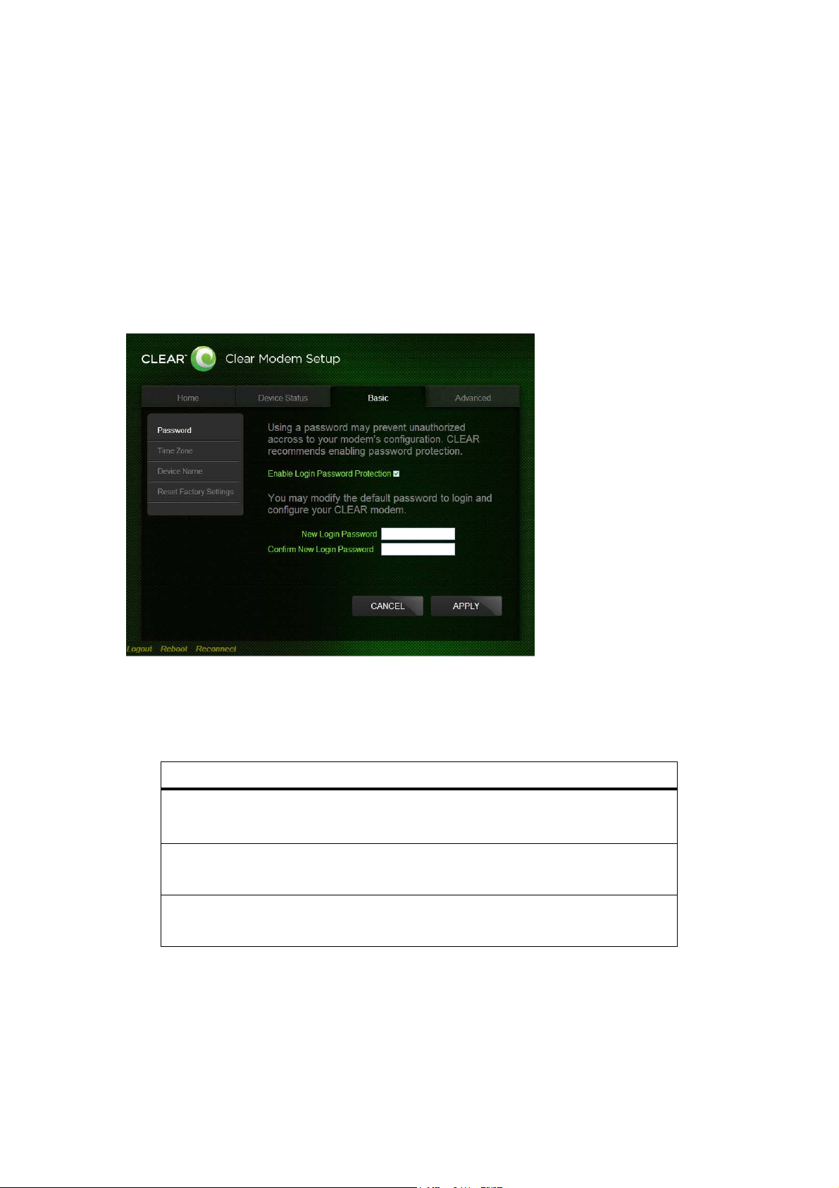
Password Tab
The password tab allows you to enable/disable password protection. You can also change
your password here.
Field or Button Description
Enable Login Password
Protection
New Login Password
Confirm New Login
Password
Be sure to click the Apply button once you are finished.
Checking this box will require login password
protection.
Enter your new password here. Maximum 20
characters. Passwords are case-sensitive.
Re-enter your new password here, exactly as
entered above.
Page 6 of 21
Page 7
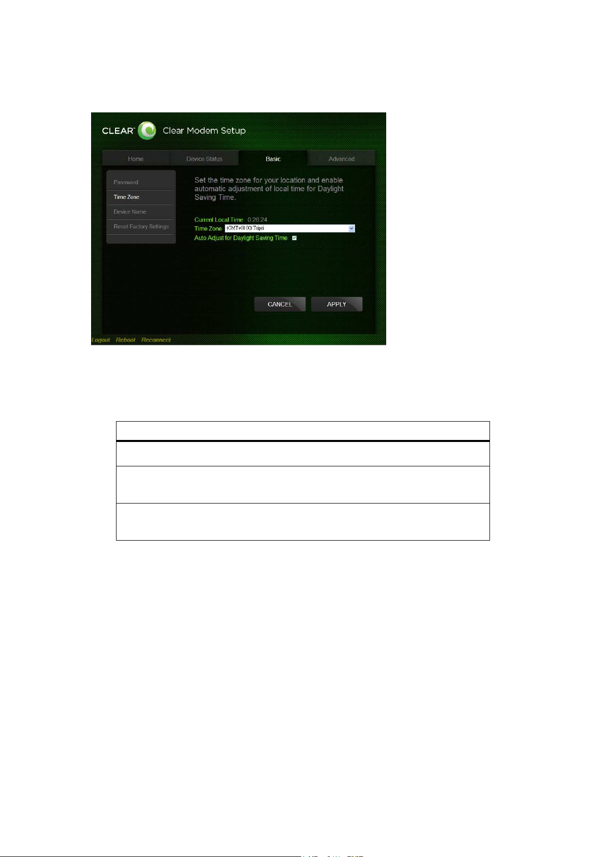
Time Zone Tab
The Device Time Zone tab allows you to establish the time zone for your location. It also
allows you to automatically adjust for Daylight Savings Time if necessary.
Field or Button Description
Current Local Time Shows the current local date and time.
Time Zone Select your local time zone from the drop down
box.
Auto Adjust for Daylight
Saving Time
Be sure to click the Apply button once you are finished.
Check this box if your location observes Daylight
Savings Time. (Default is checked)
Page 7 of 21
Page 8

Device Name Tab
The Device Name tab allows you to re-name your CPE device. This is the Device Name you
enter on an internet browser address bar to access your CPE device.
Field or Button Description
New Device Enter the new name for the CPE device.
Name Maximum 20 characters.
Be sure to click the Apply button once you are finished.
Page 8 of 21
Page 9

Restore Factory Settings Tab
The Restore Factory Settings Tab will reset your CPE to the manufacturers default settings.
Be sure to click the GO button if you are sure you want to reset factory settings. The CPE will
reboot automatically after the GO button has been clicked.
Advanced Menu
The Advanced Menu provides the following tabs:
Firewall
Internet Protocol
Dynamic DNS
Port Forwarding
Local Address
Page 9 of 21
Page 10

Firewall Tab
A firewall helps to protect your home network from unauthorized access. It will also help to
manage authorized access from the internet to your CPE
Field or Button Description
Enable Firewall Check this box to enable the firewall for your home
network.
Enable Web Login from
Internet
Web Login Port from
Internet
Enable ping from Internet Enables the CPE to respond to a ping from the
(Grayed out if Enable Firewall is not selected). Check
this box to enables you to access your CPE device
from a network other than your own.
Choose a port number to connect to when logging in
from a network other than your own. The default is
8080.
Internet. This option would be enabled to allow testing
only. Do not leave this enabled.
Be sure to click the Apply button once you are finished.
Page 10 of 21
Page 11

Internet Protocol Tab
Please check with your service provider for these settings. If you are unsure of the settings,
leave the default values set and click the Apply button
If your service provider has instructed you to change any of these settings, be sure to click the
Apply button when you are finished.
Dynamic DNS Tab
Dynamic Domain Name Service (DDNS) allows a user with a non-static IP address to keep
Page 11 of 21
Page 12

their domain name associated with an ever changing IP address. As an example, DDNS is
used when you are hosting your own website
Field or Button Description
Enable DDNS Check this box to Enable DDNS (default is
unchecked).
DDNS Service Provider
DDNS User Name
DDNS Password Only valid if Enable DDNS is checked. Enter your
DDNS Host Name Only valid if Enable DDNS is checked. Enter the
Be sure to click the Apply button once you are finished.
Port Forwarding Tab
Port forwarding enables you to direct incoming traffic to specific LAN hosts (computers on your
network) based on the protocol and port number. It is used to play Internet games or provide
Select DDNS Service Provider that you belong to
from the drop down box.
Only valid if Enable DDNS is checked. Enter your
DDNS account user name.
DDNS account password.
DDNS Host Name.This is assigned by the DDNS
service.
local services (such as web hosting) for a LAN group
The Port Forwarding Tab provides the following tabs:
Basic
Forwarding
Basic
Page 12 of 21
Page 13

Field or Button Description
Enable UPnP IGD Enables Universal Plug and Play (UPnP) Internet
Gateway Device (IGD) profile to allow certain
Windows applications to setup the port forwarding
rule dynamically when NAT is enabled on this
device.
DMZ (DeMilitarized Zone)
IP Address
Be sure to click the Apply button once you have made changes.
Forwarding
Enter the DMZ IP Address.
Page 13 of 21
Page 14

Forwarding Tab Click on the ADD button to create additional Port Fowarding rules
Field or Button Description
Select Select a box when you want to delete the specific
row.
Protocol Select TCP (Transmission Control Protocol) or UDP
(User Datagram Protocol).
WAN Port Start Enter the beginning port range for external network
access.
WAN Port End Enter the ending port range for external network
access.
LAN IP Address Enter the IP address to host the service.
LAN Port Start Enter the beginning port range for internal network
access.
LAN Port End Enter the ending port range for internal network
access.
Enabled Check to enable specific port forwarding.
Be sure to click the Apply button once you have made changes.
Local Address Menu
The Local Address menu allows you to configure your Local Area Network (LAN) connections.
The Local Address menu provides the following tabs:
Page 14 of 21
Page 15

DHCP Server
Lease Status
Lease Reservation
DHCP Server Tab
The DHCP Server tab enables Dynamic Host Configuration Protocol (DHCP) server
functionality on the LAN, allowing the router to dynamically assign lease IP addresses to
clients that connect to it from the local network.
Field or Button Description
Enable DHCP Server If selected, the DHCP server on the gateway assigns
IP addresses to the computers and other hosts on
your network if they have DHCP enabled. By default,
the gateway server is enabled. If there is another
DHCP server running on your network (on another
router), you must disable one of the DHCP servers.
DHCP Server IP Address
DHCP Starting IP
Address
Enter the default port forwarding LAN Client IP
Address.
Sets the first IP address assigned by the DHCP
server, in dotted-decimal format. It must be greater
than the IP address value of the gateway. For
example, if the IP address of the gateway is
192.168.15.1 (default), the starting IP address must
Page 15 of 21
Page 16

be 192.168.15.2 (or higher).
DHCP Ending IP
Address
DHCP Lease Time Sets the time, in seconds, that a network computer
Be sure to click the Apply button once you have made changes.
Lease Status
Sets the final IP address assigned by the DHCP
server. If the DHCP server runs out of DHCP
addresses, users cannot access network resources.
If this happens, increase the Ending IP or reduce the
Lease Time.
remains connected to the gateway using its current
assigned IP address. At the end of this time, the
DHCP server renews the lease or assigns the
computer a new IP address. The default is 3600
seconds (1 hour). The maximum is 999999 seconds
(about 278 hours).
The Lease Status tab in the Local Address menu displays the active DHCP leases since the
last reboot.
Page 16 of 21
Page 17

Field or Button Description
Client Host Name Displays the client host name. The Name field is
limited to 20 characters (only 5 appear in display).
MAC Address Media Access Control (MAC) address.
IP Address Shows the IP Address for each active lease.
Remaining Lease Duration
Be sure to click the Apply button once you have made changes.
Lease Reservation
Shows the amount of time, in seconds, remaining
in the lease.
This tab allows you to manage the lease reservation so that the same client receives the same
IP address each time.
Field or Button Description
Select Select this box if you want to delete an established
lease reservation. Be sure to click the Delete button
once you have selected your exception to be
Page 17 of 21
Page 18

deleted.
Client Host Name Enter the client host name. The Name field is limited
to 20 characters (only 5 appear in display)
MAC Address Media Access Control (MAC) address. Enter the
MAC address of the device.
IP Address Enter the IP address that you want assigned to the
MAC Address.
Enabled
Be sure to click the Apply button once you have made changes.
Checking this box enables the lease reservation.
FAQ
What are the minimum system requirements to be able to run the Clear Modem?
System Requirement Pentium II 300 MHz or better with minimum of 64MB RAM.
What operating systems are supported?
Operating Systems: Windows 2000/XP/Vista or Mac OS 8 or higher
Why my Modem is not working?
Make sure the modem’s power adapter is plugged into an active power outlet.
If you are using a power strip or surge protector, make sure its switch is in the “ON”
position.
Make sure the round end of the power adapter is firmly connected to the modem’s power
jack.
Make sure you are using the power adapter that came with your modem. The correct
adapter for the Clear Modem Series G provides output power of 12V AC at 2 Amp.
If you still see no lights, call Clear Care at 888-888-3113.
Why can’t I log on to the Modem?
Check that the Ethernet cable is properly connected to the Clear Modem and the
computer.
Why can’t I connect to the Internet?
Check the Clear Modem connection status from the Web Interface; refer to the
Connection Status section to verify the connection status.
If the Clear Modem connection is down, and the gateway has not received an IP for 5 to
10 minutes:
- Reset the Clear Modem using the reset button.
Page 18 of 21
Page 19

Why does my WiMAX signal vary?
Interference due to materials between the cell tower and the modem, including buildings
and trees, could cause the signal to be weak in specific areas, even within the coverage
area.
How do I receive the strongest signal possible?
Use the signal strength LEDs on the modem to find the room or location with the
strongest signal.
Additional Troubleshooting Help
Contact your service provider for additional help via Clear Care at 888-888-3113.
Page 19 of 21
Page 20

Regulatory Notices
Model No: WIXB-175 WiMAX CPE
Operating Frequency Range: 2.5GHz~2.7GHz
Bandwidth: 5MHz/10MHz
Operation temperature: 0 ~40℃ ℃
Federal Communication Commission Interference Statement
This equipment has been tested and found to comply with the limits for a Class B digital device,
pursuant to Part 15 of the FCC Rules. These limits are designed to provide reasonable
protection against harmful interference in a residential installation. This equipment generates,
uses and can radiate radio frequency energy and, if not installed and used in accordance with
the instructions, may cause harmful interference to radio communications. However, there is
no guarantee that interference will not occur in a particular installation. If this equipment does
cause harmful interference to radio or television reception, which can be determined by turning
the equipment off and on, the user is encouraged to try to correct the interference by one of the
following measures:
- Reorient or relocate the receiving antenna.
- Increase the separation between the equipment and receiver.
- Connect the equipment into an outlet on a circuit different from that to which the receiver
is connected.
- Consult the dealer or an experienced radio/TV technician for help.
FCC Caution: Any changes or modifications not expressly approved by Clearwire could void
the user's authority to operate this equipment.
This device complies with Part 15 of the FCC Rules. Operation is subject to the following two
conditions: (1) This device may not cause harmful interference, and (2) this device must
accept any interference received, including interference that may cause undesired operation.
IMPORTANT NOTE:
Radiation Exposure Statement:
This equipment complies with FCC radiation exposure limits set forth for an uncontrolled
environment. This equipment should be installed and operated with minimum distance 20 cm
between the radiator & your body.
This transmitter must not be co-located or operate in conjunction with any other antenna or
Page 20 of 21
Page 21

transmitter.
The availability of some specific channels and/or operational frequency bands are country
dependent and are firmware programmed at the factory to match the intended destination. The
firmware setting is not accessible by the end user.
Page 21 of 21
 Loading...