

Page 1

CellPipe® 7130
Residential Gateway
6Ve.A4111 & 6Vz.A4111 | Release 01
USER GUIDE
3EQ-10422-AAAA-TCZZA
EDITION 01
FEBRUARY 2011
Page 2

Alcatel, Lucent, Alcatel-Lucent, the Alcatel-Lucent logo, and CellPipe are trademarks of Alcatel-Lucent. All other trademarks are the property of their
respective owners.
The information presented is subject to change without notice. Alcatel-Lucent assumes no responsibility for inaccuracies contained herein.
Alcatel-Lucent provides this documentation without warranty of any kind, implied or expressed, including, but not limited to, the implied warranties of
merchantability and fitness for a particular purpose.
Copyright © 2011 Alcatel-Lucent. All rights reserved.
Conformance statements
The equipment has been tested in the regulation lab and complied with the limits for VDSL device, pursuant to Europe CE/CB, FCC and Canadian. These limits
of different regulations are designed provide reasonable protection against harmful interference or damage in a residential installation.
Security statement
In rare instances, unauthorized individuals make connections to the telecommunications network through the use of remote access features. In such an event,
applicable tariffs require the customer to pay all network charges for traffic. Alcatel-Lucent cannot be responsible for such charges and will not make any
allowance or give any credit for charges that result from unauthorized access.
IMPORTANT NOTICE: This document contains confidential information that is proprietary to Alcatel-Lucent. No part of its contents may be used, copied,
disclosed or conveyed to any party in any manner whatsoever without prior written permission from Alcatel-Lucent.
www.alcatel-lucent.com
Page 3

About this document
Purpose
This document provides information on the hardware setup, software configuration, and
administration necessary to operate the CellPipe 7130 Residential Gateway 6Ve.A4111
and 6Vz.A4111. The 6Vz.A4111 supports HPNA; 6Ve.A4111 does not.
Reason for revision
The following table shows the revision history of this document.
Revision Date Reason for reissue
Edition 01 February 2011 First release of this document
Intended audience
This document is intended for users and administrators of the CellPipe 7130 RG
6Ve.A4111 and 6Vz.A4111.
How to use this document
This document introduces the CellPipe 7130 RG 6Ve.A4111 and 6Vz.A4111 hardware,
connections, and setup. It also covers the Web configuration interface and provides
parameter definitions for the fields on those screens.
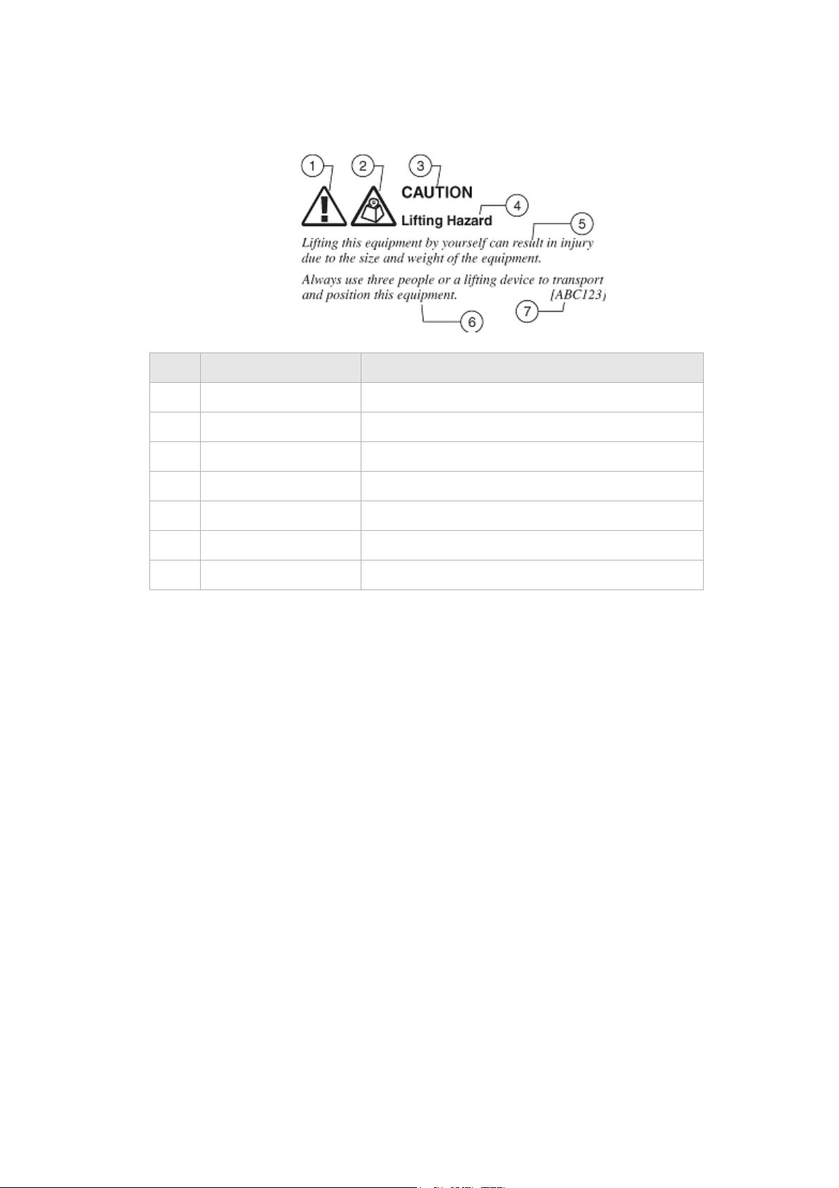
Structure of hazard statements
Overview
For the safety of you and your equipment, this document contains hazard statements.
Hazard statements are given at points where there may be a risk of damage to personnel,
equipment, or operation. Failure to follow the directions in a hazard statement may result
in personal harm, equipment damage, or network loss.
General structure
Hazard statements include the structural elements shown in the figure below.
............................................................................................................................................................................................................................................................
3EQ-10422-AAAA-TCZZA
Edition 01 February 2011
i
Page 4
About this document
............................................................................................................................................................................................................................................................
Structure of hazard statements
Item Structure element Purpose
1 Personal injury symbol Indicates the potential for personal injury (optional).
2 Hazard type symbol Indicates hazard type (optional).
3 Signal word Indicates the severity of the hazard.
Signal words
4 Hazard type Describes the source of the risk of damage or injury.
5 Damage statement Consequences if protective measures fail.
6 Avoidance message Protective measures to take to avoid the hazard.
7 Identifier The reference ID of the hazard statement (optional).
The following table defines signal words that identify the hazard severity levels.
............................................................................................................................................................................................................................................................
ii
3EQ-10422-AAAA-TCZZA
Edition 01 February 2011
Page 5

About this document
............................................................................................................................................................................................................................................................
Signal words for hazard severity
Signal word Meaning
DANGER Indicates an imminently hazardous situation (high
risk) which, if not avoided, will result in death or
serious injury.
WARNING Indicates a potentially hazardous situation (medium
risk) which, if not avoided, could result in death or
serious injury.
CAUTION When used with the personal injury symbol:
Indicates a potentially hazardous situation (low risk)
which, if not avoided, may result in personal injury.
When used without the personal injury symbol:
Indicates a potentially hazardous situation (low risk)
which, if not avoided, may result in property
damage, such as service interruption or damage to
equipment or other materials.
Related information
The documentation set accompanying this family of routers includes this User Manual and
a Quick Installation Guide.
Technical support
For technical support, contact your local Alcatel-Lucent customer support team. See the
Alcatel-Lucent Support website for contact information: https://service.esd.alcatellucent.com/portal/page/portal/EService/customer_support
Customer Service
If you experience trouble with this telephone equipment, please contact the following
address and phone number for information on obtaining service or repairs:
Alcatel-Lucent
600-700 Mountain Avenue
Murray Hill, NJ 07974
1-908-508-8080
............................................................................................................................................................................................................................................................
3EQ-10422-AAAA-TCZZA
Edition 01 February 2011
iii
Page 6

About this document
............................................................................................................................................................................................................................................................
............................................................................................................................................................................................................................................................
iv
3EQ-10422-AAAA-TCZZA
Edition 01 February 2011
Page 7

Contents
1Product overview
Hardware introduction ............................................................................................................................... 1-1
Safety precautions ..................................................................................................................................... 1-2
Prerequisites ..............................................................................................................................................1-3
Description of LEDs and interfaces .......................................................................................................... 1-3
2 Hardware installation
Mounting Procedure ..................................................................................................................................2-1
To install the CellPipe 7130 RG ................................................................................................................2-2
3 TCP/IP configuration
4 Accessing the CellPipe 7130 RG web configuration tool
To access the CellPipe 7130 RG web configuration tool ..........................................................................4-1
5 Status
System Usage ............................................................................................................................................ 5-1
WAN PTM Status ...................................................................................................................................... 5-3
DSL Link Status ........................................................................................................................................5-4
Device Table ..............................................................................................................................................5-6
DHCP Lease ..............................................................................................................................................5-7
WiFi Associate .......................................................................................................................................... 5-8
WAN/(W)LAN Statistics ........................................................................................................................... 5-8
IGMP Membership ..................................................................................................................................5-10
IGMP Statistic .........................................................................................................................................5-10
6Network
USB ........................................................................................................................................................... 6-1
LAN Setting .............................................................................................................................................. 6-2
WAN PTM Connections ............................................................................................................................ 6-4
7 WiFi Setup
WiFi Setting ............................................................................................................................................... 7-1
WiFi Security .............................................................................................................................................7-4
WiFi Access Filter .....................................................................................................................................7-6
8 Firewall Setup
Port Forwarding ......................................................................................................................................... 8-1
............................................................................................................................................................................................................................................................
3EQ-10422-AAAA-TCZZA
Edition 01 February 2011
1
Page 8

Contents
............................................................................................................................................................................................................................................................
Demilitarized Zone (DMZ) ....................................................................................................................... 8-3
UPnP ......................................................................................................................................................... 8-4
Layer 2 Filter ............................................................................................................................................. 8-5
Layer 3 Filter ............................................................................................................................................. 8-7
NAT Passthrough ...................................................................................................................................... 8-8
URL Blocking ........................................................................................................................................... 8-9
Content Screening ................................................................................................................................... 8-10
Parental Control ...................................................................................................................................... 8-12
9 Advanced Setup
Route Setting ............................................................................................................................................. 9-1
DNS Settings ............................................................................................................................................. 9-3
Dynamic DNS ........................................................................................................................................... 9-4
System Log ................................................................................................................................................ 9-5
IGMP Proxy/Snooping .............................................................................................................................. 9-6
802.1x Config ............................................................................................................................................ 9-7
10 QoS PTM Setup
QoS Overview ......................................................................................................................................... 10-1
QoS Scheduler ......................................................................................................................................... 10-2
QoS Policy .............................................................................................................................................. 10-4
QoS Phone ............................................................................................................................................... 10-7
QoS ALG ................................................................................................................................................ 10-9
QoS Defaults ......................................................................................................................................... 10-11
QoS MAC .............................................................................................................................................. 10-13
11 Utilities
Configuration Backup ............................................................................................................................. 11-1
Configuration Restore ............................................................................................................................. 11-2
Firmware Upgrade .................................................................................................................................. 11-3
System Setting ......................................................................................................................................... 11-4
Management Access Control .................................................................................................................. 11-7
CWMP Management ............................................................................................................................... 11-8
Connection Test ....................................................................................................................................... 11-9
802.1x CA Upload ................................................................................................................................ 11-10
Restore Factory Defaults ........................................................................................................................11-11
Reboot Gateway .................................................................................................................................... 11-12
............................................................................................................................................................................................................................................................
2
3EQ-10422-AAAA-TCZZA
Edition 01 February 2011
Page 9

Contents
............................................................................................................................................................................................................................................................
12 Telephony
Account Setup ..........................................................................................................................................12-1
Service Settings .......................................................................................................................................12-3
SIP Server Settings ..................................................................................................................................12-7
RTP/Codec settings ..................................................................................................................................12-9
Account & Line Table ............................................................................................................................12-11
Call History ............................................................................................................................................12-11
Other Settings ........................................................................................................................................12-12
13 USB Service
File sharing ..............................................................................................................................................13-1
Printer Server ...........................................................................................................................................13-4
14 FCC and IC Statement
Federal Communication Commission Interference Statement ................................................................14-1
FCC Part 68 Statement ............................................................................................................................14-2
Industry Canada statement .......................................................................................................................14-3
IC TELECOM .........................................................................................................................................14-4
A Troubleshooting
B Product conformance
EU declaration of conformity ................................................................................................................... B-1
GL Glossary
............................................................................................................................................................................................................................................................
3EQ-10422-AAAA-TCZZA
Edition 01 February 2011
3
Page 10

Contents
............................................................................................................................................................................................................................................................
............................................................................................................................................................................................................................................................
4
3EQ-10422-AAAA-TCZZA
Edition 01 February 2011
Page 11

1Product overview
Overview
Purpose
This chapter provides an introduction to the physical aspects of the CellPipe 7130 RG
6Ve.A4111 and 6Vz.A4111 including safety precautions, prerequisites, and descriptions.
The CellPipe 7130 RG 6Ve.A4111 and 6Vz.A4111 will be referred to as CellPipe 7130
RG throughout the rest of this document.
Contents
This chapter covers the following topics:
Hardware introduction 1-1
Safety precautions 1-2
Prerequisites 1-3
Description of LEDs and interfaces 1-3
Hardware introduction
This CellPipe 7130 RG supports Ethernet-over-VDSL2 using one Ethernet data link that is
rated up to 100 Mb/s symmetrically. With its bridge functionality, it can connect to any
device equipped with a 10BASE-T or 100BASE-TX network interface card. It supports
WAN connection via telephone cable to VDSL switch. It also supports HomePNA, USB
storage, VoIP, and wireless local area network. For this purpose, it provides:
• One VDSL port
• Four Ethernet LAN ports (10/100BASE-TX)
• One HPNA interface (Only for 6Vz.A4111)
• Two USB ports
• Wireless (802.11n)
• Two FXS ports
............................................................................................................................................................................................................................................................
3EQ-10422-AAAA-TCZZA
Edition 01 February 2011
1-1
Page 12

Safety precautionsProduct overview
............................................................................................................................................................................................................................................................
The CellPipe 7130 RG also includes router and firewall functionality.
Safety precautions
Follow these recommendations to protect yourself and the CellPipe 7130 RG from harm:
• Use volume labels to mark the type of power.
• Use the power adapter provided with the CellPipe 7130 RG.
• Pay attention to the power load of the electrical outlet or extension cord. An
overburdened power outlet or damaged cords and plugs may cause electric shock or
fire. Check the power cords regularly. If you find any damage, replace the cord
immediately.
• Leave adequate space for heat dissipation to avoid any damage caused by overheating
the CellPipe 7130 RG. Do not cover the ventilation holes.
• Do not put the CellPipe 7130 RG near a heat source. Avoid placing the CellPipe 7130
RG in direct sunlight.
• Do not put the CellPipe 7130 RG in damp or wet locations. Do not spill any liquid on
the CellPipe 7130 RG.
• Do not connect the CellPipe 7130 RG to any PC or electronic product unless our
customer engineers or your ISP instructs you to do so; incorrect connections may
cause fires.
• Do not place the CellPipe 7130 RG on an unstable surface or support.
• Do not place heavy objects on top of the CellPipe 7130 RG.
• Do not use liquid or aerosol cleaners; use a soft, dry cloth for cleaning.
"CAUTION: To reduce the risk of fire, use only No. 26 AWG or larger (e.g., 24 AWG)
UL Listed or CSA Certified Telecommunication Line Cord"
"IMPORTANT SAFETY INSTRUCTIONS - When using your telephone equipment,
basic safety precautions should always be followed to reduce the risk of fire, electric
shock and injury to persons, including the following:
• Do not use this product near water for example, near a bathtub, washbowl, kitchen
sink or laundry tub, in a wet basement or near a swimming pool.
• Avoid using a telephone (other than a cordless type) during an electrical storm.
There may be a remote risk of electric shock from lightning.
• Do not use the telephone to report a gas leak in the vicinity of the leak.
• Use only the power cord and batteries indicated in this manual. Do not dispose of
batteries in a fire. They may explode. Check with local codes for possible special
disposal instructions.
SAVE THESE INSTRUCTIONS"
............................................................................................................................................................................................................................................................
1-2
3EQ-10422-AAAA-TCZZA
Edition 01 February 2011
Page 13
PrerequisitesProduct overview
............................................................................................................................................................................................................................................................
Prerequisites
Ensure that you have the following items before attempting to use the CellPipe 7130 RG:
• Internet services subscription (connection type, account information, and addresses)
• 10/100Base-T Ethernet NIC installed in your PC
• Operating system: Windows 98SE, Windows 2000, Windows NT, Windows ME,
Windows XP, Microsoft Vista, Windows 7, or Mac OS
• Internet Explorer v4.0 or higher, Netscape v4.0 or higher, or Mozilla Firefox v1.5 or
higher
Note: For optimal display quality, use Internet Explorer v5.0 or Netscape v6.1.
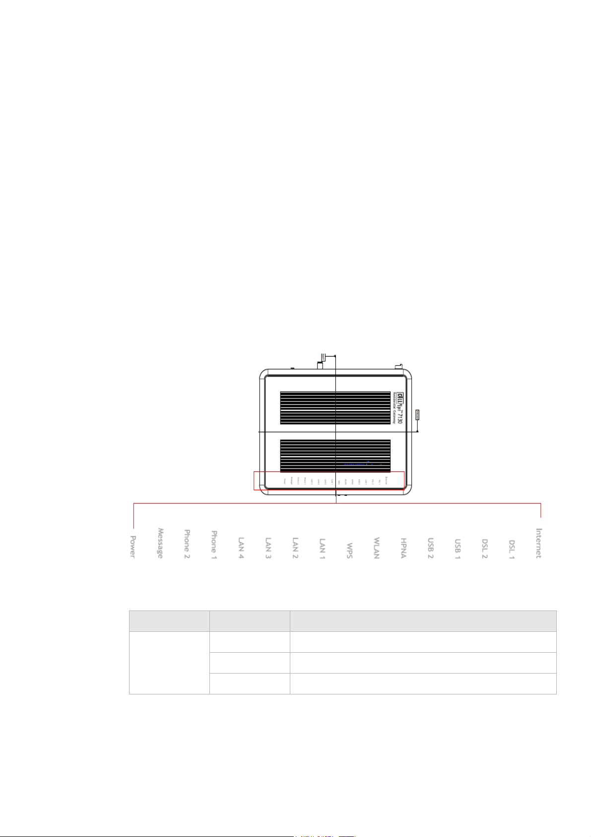
Description of LEDs and interfaces
Figure 1-1 Front panel
Table 1-1 Front panel LEDs
LED Status Description
Internet On The CellPipe 7130 RG is connected to the Internet.
Flashing Data is being transmitted over the Internet connection.
Off The CellPipe 7130 RG is not connected to the Internet.
............................................................................................................................................................................................................................................................
3EQ-10422-AAAA-TCZZA
Edition 01 February 2011
1-3
Page 14

Description of LEDs and interfacesProduct overview
............................................................................................................................................................................................................................................................
LED Status Description
DSL 1 to 2 On DSL is operating.
Flashing DSL is training.
Off DSL is disconnected.
USB 1 to 2 On A device is connected to the USB port.
Flashing USB port has data traffic.
Off No device is connected to USB port.
HPNA (Only
for
6Vz.A4111)
On HPNA interface is enabled and connected to a HPNA
device.
Flashing HPNA traffic is present.
Off HPNA interface is disabled or disconnected to any HPNA
device.
WLAN On Wireless function is enabled.
Flashing Data is being transmitted on the wireless link.
Off Wireless function is disabled.
WPS On WPS is enabled.
Off WPS is disabled.
LAN 1 to 4
On Ethernet LAN port 1 to 4 is connected and active.
Flashing Network activity over the corresponding ports.
Off Ethernet LAN port 1 to 4 is not active.
Phone 1 to 2 On Phone 1 to 2 is connected.
Off No phones are connected.
*
Message Slow flashing
Firmware upgrade in progress.
Off No firmware upgrade in progress.
Power On CellPipe 7130 RG is powered on.
Off Power is disconnected.
Notes:
* Slow flashing: LED flashes at the rate of 2 seconds on and 2 seconds off.
............................................................................................................................................................................................................................................................
1-4
3EQ-10422-AAAA-TCZZA
Edition 01 February 2011
Page 15
Description of LEDs and interfacesProduct overview
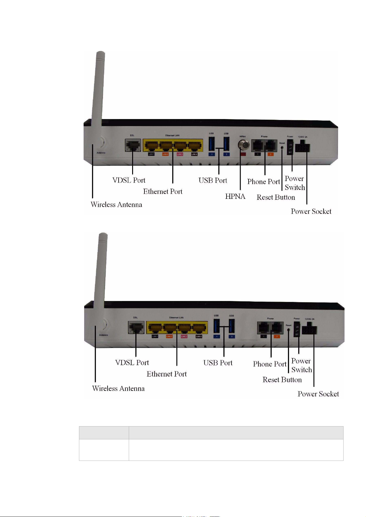
............................................................................................................................................................................................................................................................
Figure 1-2 Rear panel of 6Vz.A4111
Figure 1-3 Rear panel of 6Ve.A4111
Table 1-2 Rear panel items
Item Description
Wireless
Antenna for transmission of wireless signal.
Antenna
............................................................................................................................................................................................................................................................
3EQ-10422-AAAA-TCZZA
Edition 01 February 2011
1-5
Page 16

Description of LEDs and interfacesProduct overview
............................................................................................................................................................................................................................................................
Item Description
VDSL port Input port of the VDSL network connection from your ISP. The VDSL port
connects to a RJ-11 cable.
Ethernet ports
Four RJ-45 ports to connect up to four PCs or Hub.
1 to 4
USB Port
Support USB 2.0 file sharing and printer server.
1 to 2
HPNA
One HPNA interface to connect to a HPNA device.
interface (Only
for
6Vz.A4111)
Phone 1/2 ports Two RJ-11 ports for connecting telephones for VoIP.
Reset button Press and hold for 10 seconds to restore to factory default settings.
Power switch Power On/Off switch.
Power socket DC power adapter port.
............................................................................................................................................................................................................................................................
1-6
3EQ-10422-AAAA-TCZZA
Edition 01 February 2011
Page 17

2 Hardware installation
Overview
Purpose
This chapter provides the instructions to install the CellPipe 7130 RG hardware.
Contents
This chapter covers the following topic:
Mounting Procedure 2-1
To install the CellPipe 7130 RG 2-2
Mounting Procedure
There are multiple ways for mounting the CPE:
Wall Mounting
Pre-Requirements
Anchors
•
• Screws
• Drill & Drill bit
1. Locate a high position on the wall that is free of obstructions.
2. Connect two screws in the wall 5 cm(2 in.) apart. Do not screw the screws all the way
into the wall.
Important! Make sure that the screws are securely fixed to the wall and strong
enough to hold the weight of the CPE. (recommended screw type and size: Nylon wall
plug (T8x25mm) and screws (T3.5x16mm)).
3. Align the holes on the back of the CPE with the screws on the wall.
............................................................................................................................................................................................................................................................
3EQ-10422-AAAA-TCZZA
Edition 01 February 2011
2-1
Page 18

To install the CellPipe 7130 RGHardware installation
............................................................................................................................................................................................................................................................
4. Hang up the CPE on the screws.
Desktop Mounting
Place the CPE on top of the desk with the rubber feet standing at the bottom.
Stand-up Mounting
Snap the cradle into the holes located on the side of the CellPipe 7130 RG and then place
it on a desk so that LEDs are visible.
To install the CellPipe 7130 RG
Supplies
•
CellPipe 7130 RG
• RJ-11 telephone cable
• Two RJ-45 category 5 Ethernet cable
• Power adapter
Before you begin
CAUTION
Potential for equipment damage and personal harm
Before installing the CellPipe 7130 RG, ensure you have thoroughly read the Safety
precautions and Prerequisites in chapter 1.
Turn off all devices (computer, hub, CellPipe 7130 RG) before beginning this procedure.
............................................................................................................................................................................................................................................................
2-2
3EQ-10422-AAAA-TCZZA
Edition 01 February 2011
Page 19
To install the CellPipe 7130 RGHardware installation
............................................................................................................................................................................................................................................................
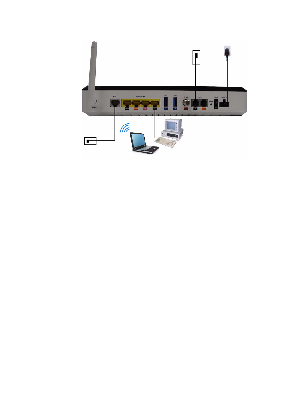
Figure 2-1 Cable connections of 6Ve.A4111 & 6Vz.A4111
Procedure
1. Connect the power adapter’s cord into the power socket on the back of CellPipe 7130
RG and plug the power adapter into a power source.
2. Connect one end of the RJ-11 cable into the VDSL port on the CellPipe 7130 RG and
the other end to your telephone/DSL service connection.
3. Connect one end of the RJ-45 Ethernet cable to one of the Ethernet LAN port (1 to 4)
on the CellPipe 7130 RG and the other end to the ethernet port on your device (such as
PC, or a hub if your are setting up Intranet).
4. Turn the power switch on.
E ND OF STEPS
........................................................................................................................................................
You must also configure the Internet properties on your computer; Please refer to the
TCP/IP Appendix or Quick Installation Guide for detailed instructions.
After setting up and configuring the CellPipe 7130 RG and your PC(s), you can access the
web configuration tool.
............................................................................................................................................................................................................................................................
3EQ-10422-AAAA-TCZZA
Edition 01 February 2011
2-3
Page 20

To install the CellPipe 7130 RGHardware installation
............................................................................................................................................................................................................................................................
............................................................................................................................................................................................................................................................
2-4
3EQ-10422-AAAA-TCZZA
Edition 01 February 2011
Page 21

3 TCP/IP configuration
Overview
The following procedures provide TCP/IP configuration instructions for all supported
operating systems.
Windows 7
1. Open Network and Internet from the Control Panel.
2. Open Network and Sharing Center from the Network and Internet.
3. Right-click Local Area Connection from Network and Sharing Center.
Windows Vista
4. Under the General tab, select Internet Protocol (TCP/IPv4), and click Properties.
5. Select the Obtain an IP address automatically radio button.
6. Select the Obtain DNS server address automatically radio button.
7. Click OK to save the settings.
E ND OF STEPS
........................................................................................................................................................
1. Open Network and sharing Center from the Control Panel.
2. Open Manage network connections from the Network and sharing Center.
3. Right-click Ethernet connection and select Properties.
4. Under the General tab, select Internet Protocol (TCP/IPv4), and click Properties.
5. Select the Obtain an IP address automatically radio button.
6. Select the Obtain DNS server address automatically radio button.
7. Click OK to save the settings.
E ND OF STEPS
........................................................................................................................................................
Windows XP
1. Open Network Connections from the Control Panel.
2. Right-click
............................................................................................................................................................................................................................................................
3EQ-10422-AAAA-TCZZA
Edition 01 February 2011
Ethernet connection and select Properties.
3-1
Page 22

OverviewTCP/IP configuration
............................................................................................................................................................................................................................................................
3. Under the General tab, select Internet Protocol (TCP/IP), and click Properties. The
Internet Protocol (TCP/IP) properties window appears.
4. Select the Obtain an IP address automatically radio button.
5. Select the Obtain DNS server address automatically radio button.
6. Click OK to save the settings.
E ND OF STEPS
........................................................................................................................................................
Windows Me/2000/98/95
1. Open Network and Dialing Connections from the Control Panel.
2. Right click the Ethernet connection icon and select Properties.
3. Select Internet Protocol (TCP/IP) component, and click Properties. The Internet
Protocol (TCP/IP) properties window appears.
4. Select the Obtain an IP address automatically radio button.
5. Select the Obtain DNS server address automatically radio button.
6. Click OK to save the settings.
Windows NT
Mac OS
E ND OF STEPS
........................................................................................................................................................
1. Open Network from the Control Panel.
2. From the Protocol tab, select the Internet Protocol (TCP/IP) component, and click
the Properties button.
3. From the IP Address tab, select the Obtain an IP address automatically radio button.
4. From the DNS tab, verify that no DNS server is defined in the DNS Service Search
Order
box and no suffix is defined in the Domain Suffix Search Order box.
E ND OF STEPS
........................................................................................................................................................
1. Open System Preferences from the Panel.
2. Choose Network from Internet & Network.
3. Make sure the window is unlocked. If it is locked, click the lock to make changes and
enter the password for authentication.
4. From the
TCP/IP tab, choose the Using DHCP on Configure IPv4 field.
5. Click on the Apply Now button to obtain an IP address from the DHCP server.
E ND OF STEPS
........................................................................................................................................................
............................................................................................................................................................................................................................................................
3-2
3EQ-10422-AAAA-TCZZA
Edition 01 February 2011
Page 23

4 Accessing the CellPipe
7130 RG web
configuration tool
Overview
Purpose
This chapter explains how to access the CellPipe 7130 RG web configuration tool by
entering the IP address and the default passwords.
The management interface software is HTML-based and can be accessed using a web
browser.
Contents
This chapter covers the following topic:
To access the CellPipe 7130 RG web configuration tool 4-1
To access the CellPipe 7130 RG web configuration tool
When to use
Use this procedure to access the web configuration interface of the CellPipe 7130 RG. The
configuration interface enables you to secure the CellPipe 7130 RG, limit access, set
traffic routes, modify passwords, and change advanced settings.
Before you begin
Before you can configure the CellPipe 7130 RG, it must be installed, connected to a webenabled PC, and turned on.
Management IP settings
To establish the initial connection, either use a computer configured to be a DHCP client,
or use a computer with IP settings in the 192.168.2.0 subnet. The IP address of the web
configuration is 192.168.2.1 with a subnet mask of 255.255.255.0.
............................................................................................................................................................................................................................................................
3EQ-10422-AAAA-TCZZA
Edition 01 February 2011
4-1
Page 24
To access the CellPipe 7130 RG web configuration toolAccessing the CellPipe 7130 RG web configuration tool
............................................................................................................................................................................................................................................................
Note: If you are not sure how to configure your computer to be a DHCP client or to
set your IP address and subnet mask, please refer to the TCP/IP Appendix or the Quick
Installation Guide for more information.
Procedure
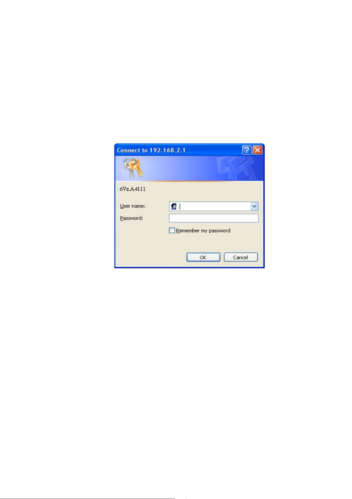
1. Open a web browser and type in the IP address of the CellPipe 7130 RG in the address
bar:
http://192.168.2.1
The login window appears; see Figure 4-1.
Figure 4-1 Login window
2. Enter your username and password and click OK.
The default admin username is admin and the default admin password is admin.
The Status window appears; see Figure 4-2.
............................................................................................................................................................................................................................................................
4-2
3EQ-10422-AAAA-TCZZA
Edition 01 February 2011
Page 25
To access the CellPipe 7130 RG web configuration toolAccessing the CellPipe 7130 RG web configuration tool
............................................................................................................................................................................................................................................................
Figure 4-2 Status window
The status window is described in Chapter 5, “Status”.
Note: Once you have logged in for the first time, you should change your login
password. See the System Setting section in the Utilities chapter for instructions.
E ND OF STEPS
........................................................................................................................................................
Configuration menus
All configuration and management of the CellPipe 7130 RG is done using the web
configuration tool. Click on the Status, Network, WiFi Setup, Firewall Setup, Advanced
Setup
information located in each directory.
, QoS Setup, Tel e p h o ny and Utilities tabs to view the configuration menus or
............................................................................................................................................................................................................................................................
3EQ-10422-AAAA-TCZZA
Edition 01 February 2011
4-3
Page 26

To access the CellPipe 7130 RG web configuration toolAccessing the CellPipe 7130 RG web configuration tool
............................................................................................................................................................................................................................................................
............................................................................................................................................................................................................................................................
4-4
3EQ-10422-AAAA-TCZZA
Edition 01 February 2011
Page 27

5 Status
Overview
Purpose
This chapter describes the contents of the Status menu, which contains the status
information for the CellPipe 7130 RG, its connections, and the connected hardware.
Click the Status drop-down menu to open the Status menu.
Contents
This chapter covers the following topics:
System Usage 5-1
WAN PTM Status 5-3
DSL Link Status 5-4
Device Table 5-6
DHCP Lease 5-7
WiFi Associate 5-8
WAN/(W)LAN Statistics 5-8
IGMP Membership 5-10
IGMP Statistic 5-10
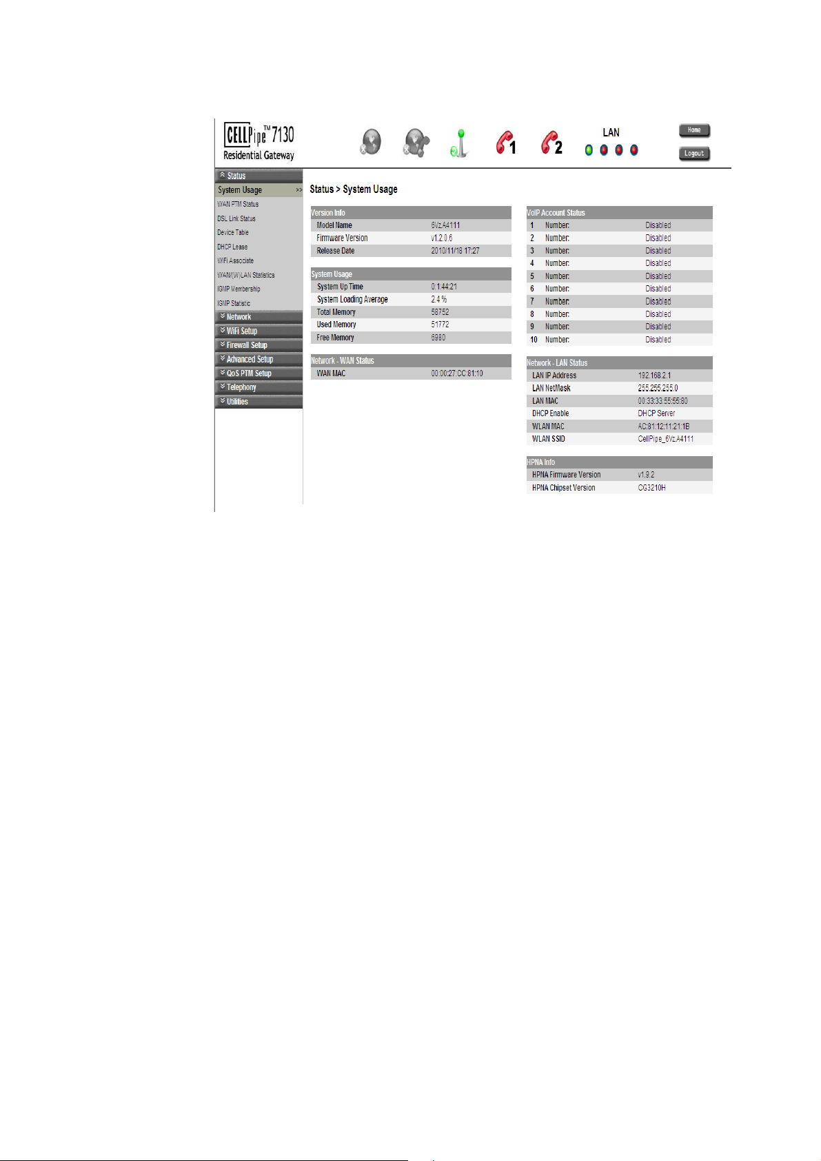
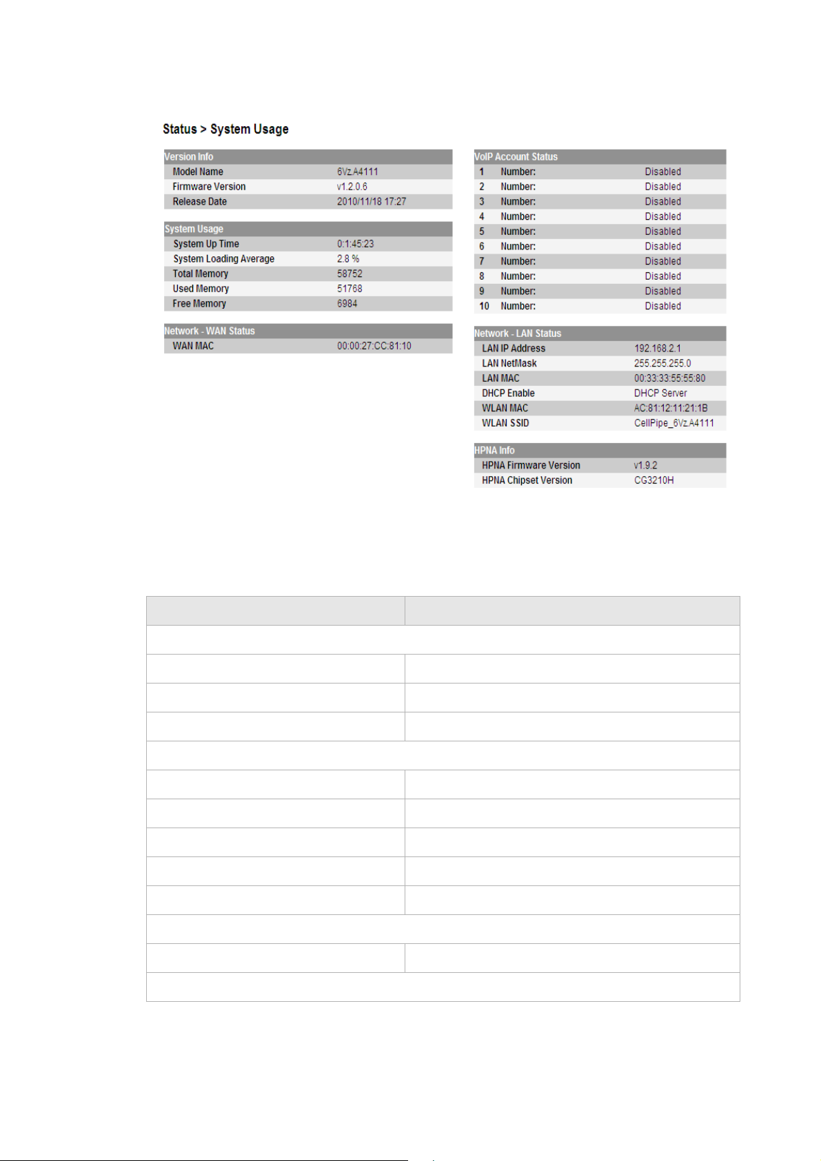
System Usage
The System Usage window displays the current status of the software, system time,
memory, WAN connection and LAN connection.
Select System Usage in the Status menu to access the System Usage window; see
Figure 5-1.
............................................................................................................................................................................................................................................................
3EQ-10422-AAAA-TCZZA
Edition 01 February 2011
5-1
Page 28
System UsageStatus
............................................................................................................................................................................................................................................................
Figure 5-1 System Usage window
Table 5-1 describes the fields of the System Usage window.
Table 5-1 Field descriptions
Field Description
Ver s i o n I nf o
Model Name The model name of the modem.
Firmware Version The current version of the firmware.
Release Date The release date of the firmware.
System Usage
System Up Time The amount of time the system has been operational.
System Loading Average The average loading of the system’s CPU.
Total Memory The memory capacity of the system in Kb.
Used Memory The memory used in the system.
Free Memory The free memory in the system.
Network - WAN Status
WAN MAC The MAC address of the WAN connection.
VoIP Account Status
............................................................................................................................................................................................................................................................
5-2
3EQ-10422-AAAA-TCZZA
Edition 01 February 2011
Page 29
WAN P T M S t atu sStatus
............................................................................................................................................................................................................................................................
Field Description
1 to 10 Number: The status (Enabled or Disabled) of accounts 1 to
10.
Network - LAN Status
LAN IP Address The IP address of the LAN interface.
LAN NetMask The subnet mask of the LAN interface.
LAN MAC The MAC address of the LAN interface.
DHCP Enable The status of the LAN DHCP.
WLAN MAC The WLAN MAC address of the WLAN interface.
WLAN SSID The service set identifier used to identify this
gateway.
HPNA Info (Only for 6Vz.A4111)
HPNA Firmware Version The current version of the HPNA firmware.
HPNA Chipset Version The current version of the HPNA chipset.
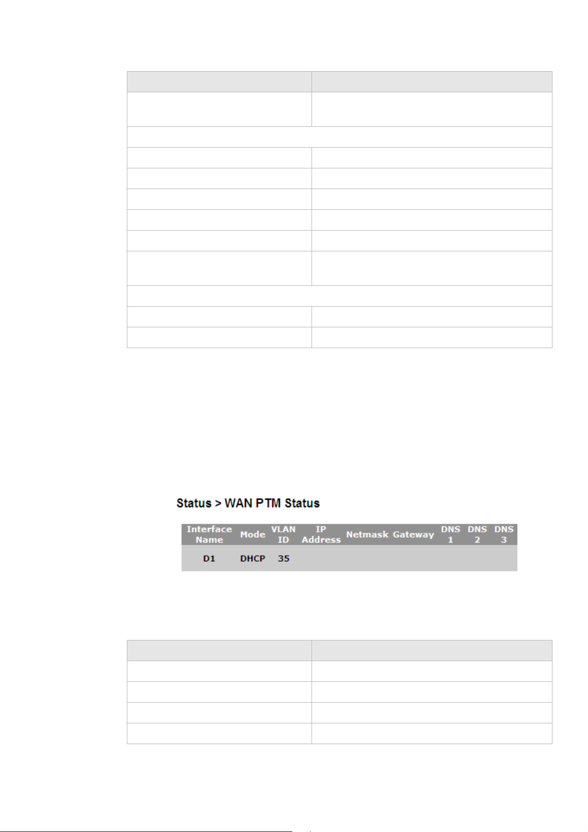
WAN PTM Sta tus
The WAN Status window displays each WAN connection’s name, mode, and connection
state. Select WAN PTM Status in the Status menu to access the WAN Status window; see
Figure 5-2.
Figure 5-2 WAN Status window
Table 5-2 describes the fields of the WAN Status window.
Table 5-2 Field descriptions
Field Description
Interface Name The name you gave to this connection.
Mode Either DHCP, PPPoE, Static IP or Bridge mode.
VLAN ID The VLAN ID number (between 2 to 4094).
IP Address The IP address of this connection.
............................................................................................................................................................................................................................................................
3EQ-10422-AAAA-TCZZA
Edition 01 February 2011
5-3
Page 30
DSL Link StatusStatus
............................................................................................................................................................................................................................................................
Field Description
Netmask The subnet mask of the IP address.
Gateway The IP address of gateway.
DNS 1 to 3 The IP address of Domain Name Server.
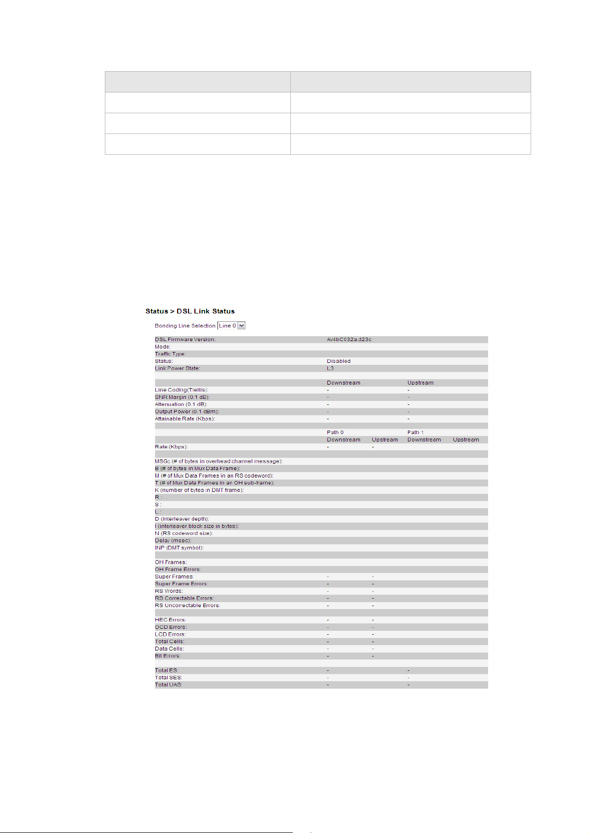
DSL Link Status
The DSL Link Status window displays the DSL connection status and data.
Select DSL Link Status in the Status menu to access the DSL Link window; see
Figure 5-3.
Figure 5-3 DSL Link Status window
Table 5-3 describes the fields of the DSL Link Status window.
............................................................................................................................................................................................................................................................
5-4
3EQ-10422-AAAA-TCZZA
Edition 01 February 2011
Page 31

DSL Link StatusStatus
............................................................................................................................................................................................................................................................
Table 5-3 Field descriptions
Field Description
DSL Firmware Version The version of firmware in use.
Mode The modulation protocol
Traffic Type The channel type
Status This is the status of the DSL link.
Link Power State Displays the power management state of the DSL
connection.
Line Coding (Trellis) The Trellis Coding status of downstream and
upstream.
SNR Margin(0.1dB) This is a signal-to-noise ratio (SNR) margin for
traffic going in both directions.
Atternuation(0.1dB) An estimate of the average loop attenuation
downstream and upstream.
Output Power(0.1dBm) The total output power in both directions.
Attainable Rate (Kbps): This is the maximum achievable downstream rate.
Rate (Kbps) The actual rate at which data is flowing in both
directions.
MSGc (# of bytes in overhead channel
Number of bytes in overhead channel message
message)
B (# of bytes in Mux Data Frame) Number of bytes in Mux Data Frame
M (# of Mux Data Frames in an RS
Number of Mux Data Frames in FEC Data Frame
codeword)
T (# of Mux Data Frames in a OH sub-
Mux Data Frames over sync bytes
frame)
K (number of bytes in DMT frame) This is the number of data bytes in an DSL data
frame.
R The number of redundant check bytes per Reed-
Solomon code word.
S The length of the Reed-Solomon code word, in data
frames.
L Number of bits in PMD Data Frame
D (interleabver depth) The interleaver depth.
I (interleaver block size in bytes) Number of bytes in interleaver block size
N (RS codeword size) The size of RS codeword.
Delay (msec) The delay, in microseconds, of the DSL connection.
............................................................................................................................................................................................................................................................
3EQ-10422-AAAA-TCZZA
Edition 01 February 2011
5-5
Page 32

Device TableStatus
............................................................................................................................................................................................................................................................
Field Description
INP (DMT symbol) INP:Impulse Noise Protection DMT:Discrete Multi-
tone
OH Frames The number of overhead frames.
OH Frame Errors The number of overhead frame errors.
Super Frames This is the total number of super frames.
Super Frame Errors The number of super frames received that had
errors.
RS Words This is the total number of Reed-Solomon code
words.
RS Correctable Errors The number of Reed-Solomon code words with
correctable errors.
RS Uncorrectable Errors The number of R-S code words that had
uncorrectable errors.
HEC Errors The total number of header error checksum errors.
OCD Errors The number of out-of-cell delineation errors.
LCD Errors The total of lost-cell-delineation errors.
Total Cells Total number of cells.
Data Cells The number of data cells.
Bit Errors The number of Bit Error.
Total ES Total number of Errored Seconds.
Total SES Total number of Severely Errored Seconds.
Total UAS Total number of Unavailable Seconds.
Device Table
The Device Table displays information about the device that has connected to the CellPipe
7130 RG.
Select Device Table in the Status menu to access the Device Table; see Figure 5-4.
............................................................................................................................................................................................................................................................
5-6
3EQ-10422-AAAA-TCZZA
Edition 01 February 2011
Page 33

DHCP LeaseStatus
............................................................................................................................................................................................................................................................
Figure 5-4 Device Table window
Table 5-4 describes the fields of the Device Table window.
Table 5-4 Field descriptions
Field Description
Host Name The name of the device that has connected to the
gateway.
IP Address The IP address of the device.
Attached By How the device connected to the gateway.
MAC Address The MAC address of the device.
DHCP Lease
The DHCP Lease Table lists the IP addresses that are leased to the DHCP clients.
Select DHCP Lease Table in the Status menu to access the DHCP Lease Table; see
Figure 5-5.
Figure 5-5 DHCP Lease window
Table 5-5 describes the fields of the DHCP Lease Table window.
Table 5-5 Field descriptions
Field Description
No. The number of client.
IP Address The IP address that is leased to the DHCP client
computer.
MAC Address The MAC address of the DHCP client computer.
............................................................................................................................................................................................................................................................
3EQ-10422-AAAA-TCZZA
Edition 01 February 2011
5-7
Page 34

WiFi AssociateStatus
............................................................................................................................................................................................................................................................
Field Description
Host Name The host name of the DHCP client computer.
Vendor Class Identifier The DHCP client platform.
Expiry The time left before this lease expires.
WiFi Associate
The WiFi Associate Table lists the current wireless clients that have connected to the
CellPipe 7130 RG
Select WiFi Associate in the Status menu to access the WiFi Associate Table; see
Figure 5-6.
Figure 5-6 WiFi Associate window
Table 5-6 describes the fields of the WiFi Associate window.
Table 5-6 Field descriptions
Field Description
No. The index number of entry in the table.
MAC The MAC address of the wireless device.
Rate The transmission rate of the wireless device.
WAN/(W)LAN Statistics
The WAN/(W)LAN Statistics window displays the number of bytes that have been
received or transmitted by the WAN, LAN, and WLAN interfaces.
Select WAN/(W)LAN Statistics in the Status menu to access the Statistics window; see
Figure 5-7.
............................................................................................................................................................................................................................................................
5-8
3EQ-10422-AAAA-TCZZA
Edition 01 February 2011
Page 35

WAN/(W)LAN StatisticsStatus
............................................................................................................................................................................................................................................................
Figure 5-7 WAN/(W)LAN Statistics window
Table 5-7 describes the WAN, LAN, and WLAN fields of the Statistics window.
Table 5-7 Field descriptions
Field Description
RX bytes The number of bytes that have been received.
RX Packets The number of packets that have been received.
RX Errors The number of packets that have been received with
errors.
RX Dropped The number of packets that have been dropped after
receiving.
TX bytes The number of bytes that have been transmitted.
TX Packets The number of packets that have been transmitted.
............................................................................................................................................................................................................................................................
3EQ-10422-AAAA-TCZZA
Edition 01 February 2011
5-9
Page 36

IGMP MembershipStatus
............................................................................................................................................................................................................................................................
Field Description
TX Errors The number of packets that have been transmitted
with errors.
TX Dropped The number of packets that have been dropped after
transmitting.
Collided instead of Collisioned The number of packets collided when transmitted.
IGMP Membership
The IGMP Membership window displays the IGMP (Internet Group Membership
Protocol) members.
Select IGMP Membership in the Status menu to access the IGMP Membership
windows; see Figure 5-8.
Figure 5-8 IGMP Membership window
Table 5-8 describes the IGMP membership window.
Table 5-8 Field descriptions
Field Description
Multicast IP Group The respective Multicast Group.
Client Lists the clients belong to the specific multicast
group.
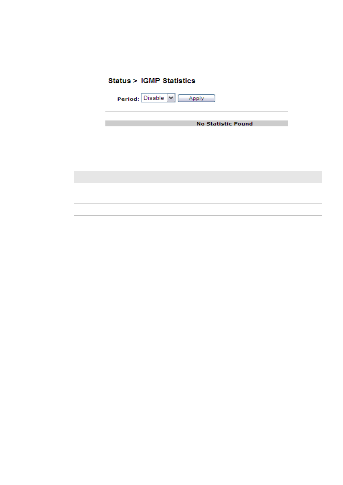
IGMP Statistic
The IGMP Statistic shows the IGMP(Internet Group Membership Protocol) Statistic.
............................................................................................................................................................................................................................................................
5-10
3EQ-10422-AAAA-TCZZA
Edition 01 February 2011
Page 37
IGMP StatisticStatus
............................................................................................................................................................................................................................................................
Select IGMP Statistic in the Status menu to access the IGMP Membership windows; see
Figure 5-9.
Figure 5-9 IGMP Statistic window
Table 5-9 describes the IGMP Statistic window.
Table 5-9 Field descriptions
Field Description
Period Select a time period form the list to collect and
display the IGMP statistics during that period.
Apply Click to show IGMP Group information.
............................................................................................................................................................................................................................................................
3EQ-10422-AAAA-TCZZA
Edition 01 February 2011
5-11
Page 38

IGMP StatisticStatus
............................................................................................................................................................................................................................................................
............................................................................................................................................................................................................................................................
5-12
3EQ-10422-AAAA-TCZZA
Edition 01 February 2011
Page 39

6Network
Overview
Purpose
This chapter explains how to configure the network settings for the CellPipe 7130 RG
from the Network menu.
Click the Network drop-down menu to open the Network menu.
Contents
This chapter covers the following topics:
USB
USB 6-1
LAN Setting 6-2
WAN PTM Connections 6-4
The USB window enables you to configure the USB storage name, USB printer name and
DMS.
Select
USB in the Network menu to access the USB&DMS window; see Figure 6-1.
............................................................................................................................................................................................................................................................
3EQ-10422-AAAA-TCZZA
Edition 01 February 2011
6-1
Page 40

LAN SettingNetwork
............................................................................................................................................................................................................................................................
Figure 6-1 USB window
Table 6-1 describes the fields of the USB window.
Table 6-1 Field descriptions
Field Description
USB Printer Enable Click the radio button to enable or disable USB
USB Printer Name Enter a USB printer name.
DMS Enable Click the radio button to enable or disable DMS.
DMS Server Name Enter a DMS Server name.
Apply Changes Click to save your changes.
Refresh Click to refresh the state of USB device.
LAN Setting
The LAN Settings include the IP address, subnet mask, DHCP settings, DHCP relay, and
static IP lease.
Select LAN Setting in the Network menu to access the LAN Setting window; see
Figure 6-2.
Printer.
............................................................................................................................................................................................................................................................
6-2
3EQ-10422-AAAA-TCZZA
Edition 01 February 2011
Page 41

LAN SettingNetwork
............................................................................................................................................................................................................................................................
Figure 6-2 LAN Setting window
Table 6-2 describes the fields of the LAN Setting window.
Table 6-2 Field descriptions
Field Description
IP Address The IP address of the LAN interface in dotted
decimal notation. The default is 192.168.2.1. You
can change this address as needed to an address that
is reserved for private use.
............................................................................................................................................................................................................................................................
3EQ-10422-AAAA-TCZZA
Edition 01 February 2011
6-3
Page 42

WAN PTM Co n n e c t i o nsNetwork
............................................................................................................................................................................................................................................................
Field Description
Subnet Mask The subnet mask of the IP addresses in your LAN;
for example, 255.255.255.0.
DHCP Server If enabled, the CellPipe 7130 RG automatically
assigns IP addresses, default gateway, and DNS
servers to computers that support the DHCP client;
for example, Windows 95, Windows NT.
DHCP Starting IP Address
DHCP Ending IP Address
DHCP Lease Time The time period during which the computers retain
Static Lease Assign a static IP to DHCP clients based on their
Block Lease The client's MAC address to be blocked from
Apply Changes Click to save your changes.
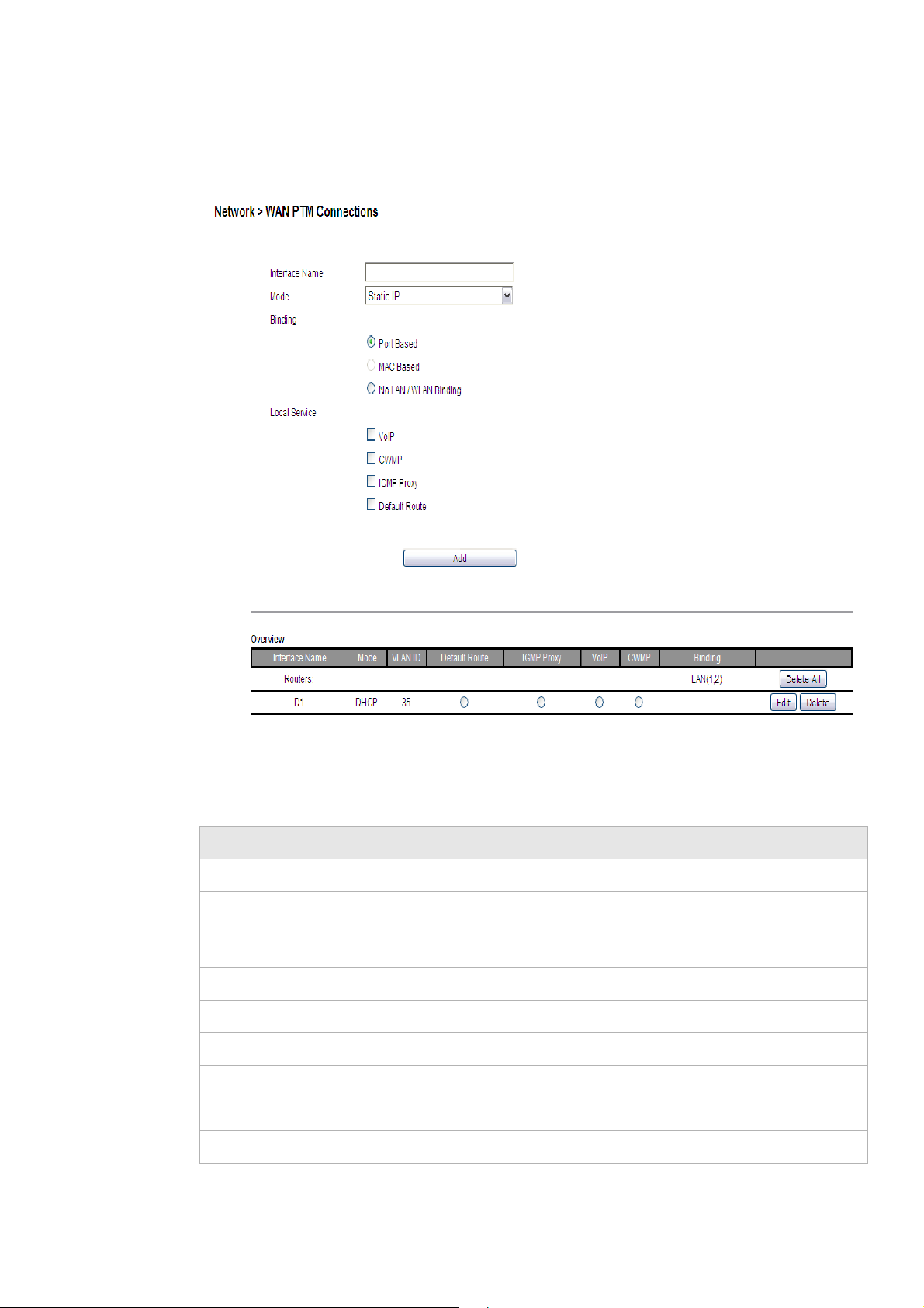
WAN PTM Connections
WAN PTM Connections are the connections used when the device operates in DSL-PTM
mode (if you are uncertain wether your DSL service is PTM, contact your ISP). The WAN
PTM Connections window enables you to configure multiple connections.
The range of IP addresses that will be assigned to the
DHCP client.
the IP addresses assigned to them.
MAC address.
acquiring an IP address.
CAUTION
It is recommended that the WAN PTM connections be changed by trained service
personnel. Improper configuration can lead to loss of connectivity to the residential
gateway from the LAN side as well as the WAN side.
There are three different binding methods for the connections:
• Port based binding
• MAC based binding
• No LAN/WLAN binding
The four following types of connections can be used:
• Static IP
• DHCP Mode
• PPPoE Mode
• Bridge Mode
............................................................................................................................................................................................................................................................
6-4
3EQ-10422-AAAA-TCZZA
Edition 01 February 2011
Page 43
WAN PTM ConnectionsNetwork
............................................................................................................................................................................................................................................................
Select WAN PTM Connections in the Network menu to access the WAN PTM
Connections window; see Figure 6-3.
Figure 6-3 WAN PTM Connections window
Table 6-3 describes the fields of the WAN PTM Connection window.
Table 6-3 Field descriptions
Field Description
Interface Name Enter an appropriate name for your new connection.
Mode Click the drop-down menu and select either Static
IP, DHCP, PPPoE, or Bridge as the connection
type.
Binding
Port Based Bind the interface by LAN or WLAN port
MAC Based Bind the interface by physical MAC address
No LAN/WLAN Binding The interface does not bind to any Port or MAC
Local Service
VoIP Provide VoIP service to be used.
............................................................................................................................................................................................................................................................
3EQ-10422-AAAA-TCZZA
Edition 01 February 2011
6-5
Page 44

WAN PTM Co n n e c t i o nsNetwork
............................................................................................................................................................................................................................................................
Field Description
CMWP (CPE WAN Management
Protocol)
IGMP (Internet Group Management
Protocol) Proxy
Default Route Set the connection as the gateway of last resort,
Add Click to add the new connection and brings you to
Delete All Delete all connections below in the table.
Edit Modify the connection setting.
Delete Delete the connection.
Port based binding
Port based mode enables you to bind ports to your WAN connection. You can bind LAN
ports 1 to 4 and WLAN SSID 1 to 4 in the WAN mode you selected. The default WLAN
SSID number is 1 and you can configure 2 to 4 in the WiFi Setting.
Provide remote control service. It will allow remote
ACS server to manage this gateway.
Provide service to be used for video streaming and
gaming.
every unknown packet will be forwarded via default
route.
next step.
You can select the Port Based radio button for each WAN mode and then click Add to
proceed to the next configuration window.
In Port based mode, you can add up to four connections in routed mode.
Note: If you do not set a VLAN ID in the connections, you can only have one
connection in Static IP or DHCP mode and three connections maximum in PPPoE.
Note: If you already have a connection with Port based binding, you can not select
MAC based binding for any other connections.
The following WAN modes support port-based binding:
• Static IP
• DHCP
• PPPoE
• Bridge
Static IP
If you select Static IP as the mode in the WAN PTM Connections, the Static IP settings
window with Port based binding opens; see Figure 6-4.
............................................................................................................................................................................................................................................................
6-6
3EQ-10422-AAAA-TCZZA
Edition 01 February 2011
Page 45

WAN PTM ConnectionsNetwork
............................................................................................................................................................................................................................................................
Figure 6-4 Static IP settings window with Port Based Binding
Table 6-4 describes the fields of the Static IP setting window with Port Based Binding.
Table 6-4 Field descriptions
Field Description
LAN Binding Select Lan port, HPNA (Only for 6Vz.A4111) port
and WLAN port to bind the connection.
Wan
Untagged Select this option if VLAN ID is not being used.
Always Use ID Select this option if VLAN ID is used and enter the
VLAN ID number (between 2 and 4094)
IP Address Enter the IP address provided by your ISP.
NetMask Enter the subnet mask provided by your ISP.
Gateway Enter the gateway’s IP address provided by your
ISP.
DNS1/2/3 Enter the DNS IP address. They are optional.
............................................................................................................................................................................................................................................................
3EQ-10422-AAAA-TCZZA
Edition 01 February 2011
6-7
Page 46

WAN PTM Co n n e c t i o nsNetwork
............................................................................................................................................................................................................................................................
Field Description
Options
MTU Select Auto to set the maximum transfer unit to the
default (1500), or select Manual to manually enter a
value.
Next Click to go to next step.
Back Click to go back to previous page.
Activate WAN Settings Click to activate the connection.
Delete All Click to remove all WAN connections.
Edit Click to modify a specific connection.
Delete Click to remove a specific connection.
DHCP
If you select DHCP as the mode in the WAN PTM Connections window, the DHCP settings
window with Port based binding opens; see Figure 6-5.
............................................................................................................................................................................................................................................................
6-8
3EQ-10422-AAAA-TCZZA
Edition 01 February 2011
Page 47

WAN PTM ConnectionsNetwork
............................................................................................................................................................................................................................................................
Figure 6-5 DHCP settings window with Port Based Binding
Table 6-5 describes the fields of the DHCP Mode setting window with Port Based
Binding.
Table 6-5 Field descriptions
Field Description
LAN Binding Select LAN port, HPNA(Only for 6Vz.A4111) port
and WLAN port to bind the connection.
WA N
Untagged Select this option if VLAN ID is not being used.
Always Use ID Select this option if VLAN ID is used and enter the
VLAN ID number (between 2 and 4094)
802.1x Select Enable to enable 802.1x, or select Disable to
disable 802.1x. Please consult with your ISP for
more information.
DHCP Options
............................................................................................................................................................................................................................................................
3EQ-10422-AAAA-TCZZA
Edition 01 February 2011
6-9
Page 48

WAN PTM Co n n e c t i o nsNetwork
............................................................................................................................................................................................................................................................
Field Description
Host Name
Domain Name
Enter the appropriate Host Name and Domain Name
provided by your ISP. If you are not sure, please
consult with your ISP for more information.
Vender Class ID
Client ID
You may also need to set the Client ID or Vender
Class ID to obtain its lease from the DHCP server.
Please consult with your ISP for more information.
MTU (Bytes) Enable Auto to set the maximum transfer unit to the
default (1500), or enable Manual to manually enter
a value.
Next Click to go to next step.
Back Click to go back to preview page.
Activate WAN Settings Click to activate the connection.
Delete All Click to remove all WAN connections.
Edit Click to modify a specific connection.
Delete Click to remove a specific connection.
PPPoE
If you select PPPoE as the mode in the WAN PTM Connections window, the PPPoE
settings window with Port based binding opens; see Figure 6-6.
............................................................................................................................................................................................................................................................
6-10
3EQ-10422-AAAA-TCZZA
Edition 01 February 2011
Page 49

WAN PTM ConnectionsNetwork
............................................................................................................................................................................................................................................................
Figure 6-6 PPPoE Mode settings window with Port Based Binding
Table 6-6 describes the fields of PPPoE Mode setting window with Port Based Binding.
Table 6-6 Field descriptions
Fields Description
LAN Binding Select LAN port, HPNA(Only for 6Vz.A4111) port and WLAN port
to bind the connection.
WA N
Untagged Select this option if VLAN ID is not being used.
Always use ID Select this option if VLAN ID is used and enter the VLAN ID
number (between 2 and 4094)
User Name Enter the user name for the PPPoE connection.If you are not sure,
please consult with your ISP for more information.
............................................................................................................................................................................................................................................................
3EQ-10422-AAAA-TCZZA
Edition 01 February 2011
6-11
Page 50

WAN PTM Co n n e c t i o nsNetwork
............................................................................................................................................................................................................................................................
Fields Description
Password Enter the password for the PPPoE connection.If you are not sure,
please consult with your ISP for more information.
Access Concentrator The access concentrator is optional. Please consult with your ISP
for information.
Service Name The service name is optional. Please consult with your ISP for
information.
Mode
Connect on demand:
Max idle time
Select this option to let the gateway connect to Internet only when
your trying to access it. If there are no activities in the specified
period (Max idle time), the gateway will disconnect the connection.
Always on Select this option to let the gateway always connected to the
Internet.
Manual Select and then click Connect to manually connect the router to
the Internet. Click Disconnect to disconnect the connection.
Options
Authentication Mode Select the authentication mode from the drop-down menu. Options
include:
• CHAP + PAP
• Only MS-CHAP
• Only CHAP
• Only PAP
This is optional. Your ISP will provide this information if it is
necessary.
MTU (bytes) Select Auto to set the maximum transfer unit to the default (1492),
or enable Manual to manually enter a value.
Next Click to go to next step.
Back Click to go back to previous page.
Activate WAN Settings Click to activate the connection.
Delete All Click to remove all WAN connections.
Edit Click to modify a specific connection.
Delete Click to remove a specific connection.
Bridge
If you select Bridge as the mode in the WAN PTM Connections window, the Bridge
settings window with Port based binding opens; see Figure 6-7.
............................................................................................................................................................................................................................................................
6-12
3EQ-10422-AAAA-TCZZA
Edition 01 February 2011
Page 51
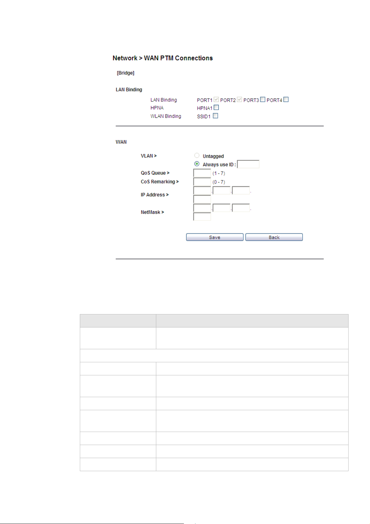
WAN PTM ConnectionsNetwork
............................................................................................................................................................................................................................................................
Figure 6-7 Bridge Mode settings window with Port Based binding
Table 6-7 describes the fields of the Bridge Mode setting window with Port Based
binding.
Table 6-7 Field descriptions
Fields Description
LAN Binding Select LAN port, HPNA(Only for 6Vz.A4111) port and WLAN port
to bind the connection.
WA N
Untagged Select this option if VLAN ID is not being used.
Always Use ID Select this option if VLAN ID is used and enter the VLAN ID
number (between 2 and 4094)
QoS Queue Enter a queue number (0 to 7) to assign to the incoming traffic.
CoS Remarking Enable New Cos Value to assign CoS (class of service) for
incoming traffic.
IP Address Enter the given IP address for your connection.
NetMask Enter the subnet mask for your connection.
Save Click to save your setting.
............................................................................................................................................................................................................................................................
3EQ-10422-AAAA-TCZZA
Edition 01 February 2011
6-13
Page 52

WAN PTM Co n n e c t i o nsNetwork
............................................................................................................................................................................................................................................................
Fields Description
Back Click to back preview page.
Activate WAN Settings Click to activate the connection.
Delete All Click to remove all WAN connections.
Edit Click to modify a specific connection.
Delete Click to remove a specific connection.
MAC based binding
MAC based mode enables you to bind your connection by DHCP Option 60, Ethernet
type, source MAC, or destination MAC.
Before you begin, you must configure a default connection. It should be routed or bridge
mode. Afterwards you can configure MAC based binding (the other binding options are
Port based and No LAN/WLAN) by DHCP Option 60, Ethernet type, source MAC, or
destination MAC.
DHCP Mode
You can select the MAC Based radio button for each WAN mode and then click Add to
enter the next configuration window.
You can set a maximum of 20 connections in MAC based binding.
Note: If you already have a connection with MAC based binding, you cannot select
Port based binding for any other connections.
The following section shows the creation of a default DHCP connection with MAC based
binding.
If you select DHCP as the mode, the DHCP settings window with MAC based binding
opens; see Figure 6-8.
............................................................................................................................................................................................................................................................
6-14
3EQ-10422-AAAA-TCZZA
Edition 01 February 2011
Page 53

WAN PTM ConnectionsNetwork
............................................................................................................................................................................................................................................................
Figure 6-8 DHCP settings window
Table 6-8 describes the fields of the DHCP Mode setting window.
Table 6-8 Field descriptions
Fields Description
LAN Binding
Default The first rule must be the default. After you have a default rule you
can choose the other options. For example, you can select DHCP
Option 60, Ethernet Type, Source MAC, or Destination MAC.
DHCP Option 60 Select the radio button and enter the applicable alphanumeric
identification (wildcard * is also applicable).
Ethernet Type Select the radio button and enter the applicable Ethernet Type code
(4 hex digits).
Source MAC Select the radio button and enter the applicable Source MAC
address in hexadecimal format.
............................................................................................................................................................................................................................................................
3EQ-10422-AAAA-TCZZA
Edition 01 February 2011
6-15
Page 54

WAN PTM Co n n e c t i o nsNetwork
............................................................................................................................................................................................................................................................
Fields Description
Destination MAC Select the radio button and enter the applicable Destination MAC
address in hexadecimal format.
WAN
VLAN Select Untagged if VLAN tagging is not to be used for this WAN
connection.
Select Always use ID if VLAN tagging is to be used and enter the
VLAN ID number (between 0 and 4094).
802.1x Select Enable to use 802.1x or select Disable to turn off 802.1x.
Please consult your ISP for more information.
Host Name Enter the host name provided by your ISP. Please consult with your
ISP for more information.
Domain Name Enter the domain name provided by your ISP. Please consult with
your ISP for more information.
Vender Class ID If you are required, set the vender class ID to obtain its lease from
the DHCP server. Please consult with your ISP for more
information.
Client ID If you are required, set the client ID to obtain its lease from the
DHCP server. Please consult with your ISP for more information.
MTU(Bytes) Select Auto to set the MTU to the default (1500) or select Manual
and enter a value in bytes.
Next Click to go to the QoS Defaults window.
Back Click to return to the previous page.
Now that you have a default connection, the WAN PTM Connections window with MAC
based binding opens; see Figure 6-9.
............................................................................................................................................................................................................................................................
6-16
3EQ-10422-AAAA-TCZZA
Edition 01 February 2011
Page 55

WAN PTM ConnectionsNetwork
............................................................................................................................................................................................................................................................
Figure 6-9 WAN PTM Connections window with MAC based binding
After you have a default connection, you can choose the WAN Mode you want and click
Add to add a new connection. You can only choose Bridge mode with MAC based
binding. Click Add to set the configurations.
Bridge Mode
When you select Bridge mode with MAC based binding and click Add, the Bridge settings
window with MAC based binding opens; see Figure 6-10.
............................................................................................................................................................................................................................................................
3EQ-10422-AAAA-TCZZA
Edition 01 February 2011
6-17
Page 56

WAN PTM Co n n e c t i o nsNetwork
............................................................................................................................................................................................................................................................
Figure 6-10 Bridge Mode settings window with MAC based binding
Table 6-9 describes the fields of Bridge Mode setting window with MAC based binding.
Table 6-9 Field descriptions
Fields Description
LAN Binding
Default The first rule must be the default. After you have a default rule you
can choose the other options. For example, you can select DHCP
Option 60, Ethernet Type, Source MAC, or Destination MAC.
DHCP Option 60 Select the radio button and enter the applicable alphanumeric
identification (wildcard * is also applicable).
Ethernet Type Select the radio button and enter the applicable Ethernet Type code
(4 hex digits).
Source MAC Select the radio button and enter the applicable Source MAC
address in hexadecimal format.
Destination MAC Select the radio button and enter the applicable Destination MAC
address in hexadecimal format.
WAN
............................................................................................................................................................................................................................................................
6-18
3EQ-10422-AAAA-TCZZA
Edition 01 February 2011
Page 57

WAN PTM ConnectionsNetwork
............................................................................................................................................................................................................................................................
Fields Description
VLAN Select Untagged if VLAN tagging is not to be used for this WAN
connection.
Select Always use ID if VLAN tagging is to be used and enter the
VLAN ID number (between 0 and 4094).
CoS Remarking Enter the CoS remarking number.
IP Address Enter the IP address provided by your ISP.
NetMask Enter the subnet mask provided by your ISP.
Next Click to proceed to the next step.
Back Click to return to the previous page.
After the second connection is set, you are returned to the WAN PTM Connections
window; see Figure 6-11. The two new connections, default and bridged, appear in the
Overview table.
............................................................................................................................................................................................................................................................
3EQ-10422-AAAA-TCZZA
Edition 01 February 2011
6-19
Page 58
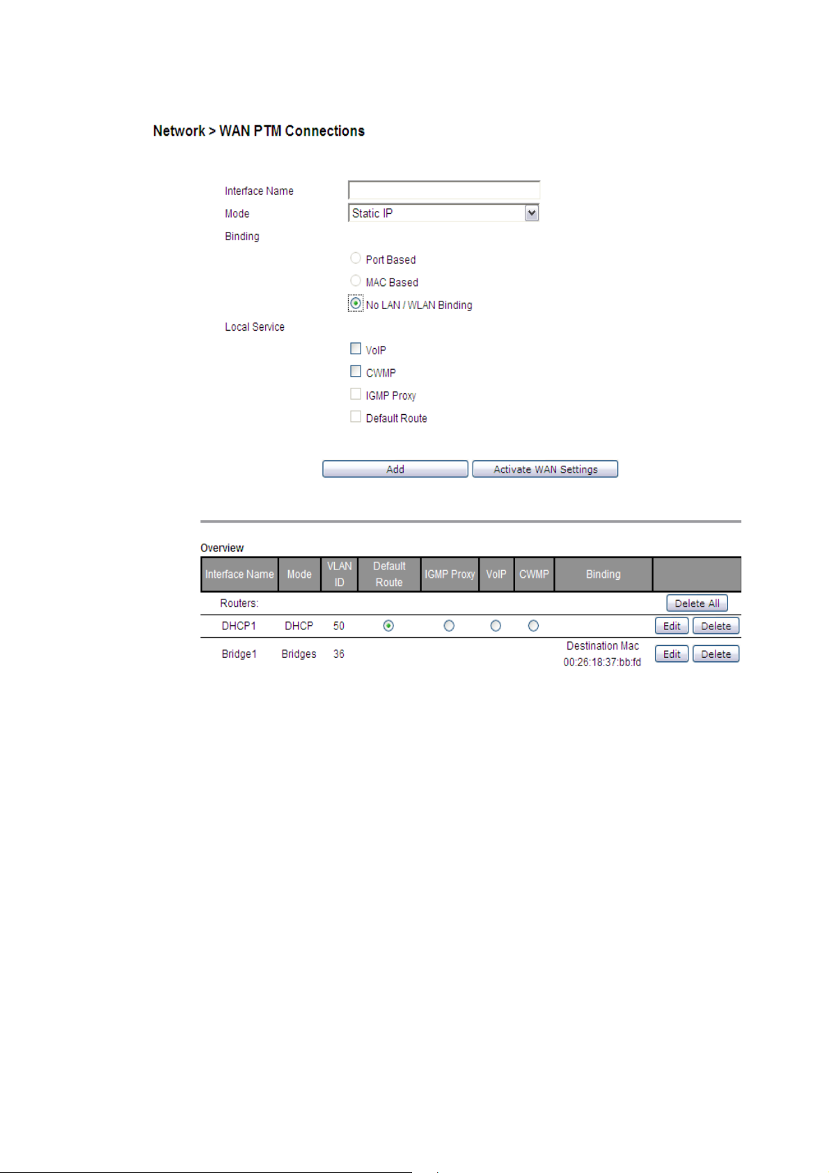
WAN PTM Co n n e c t i o nsNetwork
............................................................................................................................................................................................................................................................
Figure 6-11 WAN PTM Connections window with MAC based binding
You can only choose Bridge mode with MAC based binding and you can select Static IP,
DHCP, or PPPoE with No LAN/WLAN Binding for CWMP and VoIP.
No LAN/WLAN binding
No LAN/WLAN binding enables you to configure your connection with local service
CWMP and VoIP. In order to avoid other connections using CWMP and VoIP, No
LAN/WLAN Binding is specifically for CWMP and VoIP to build an independent
connection.
Select the No LAN/WLAN Binding radio button for the binding method and then click Add
to enter the next configuration page.
Static IP
If you select Static IP as the mode and click Add, the Static IP window with No
LAN/WLAN Binding opens; see Figure 6-12.
............................................................................................................................................................................................................................................................
6-20
3EQ-10422-AAAA-TCZZA
Edition 01 February 2011
Page 59
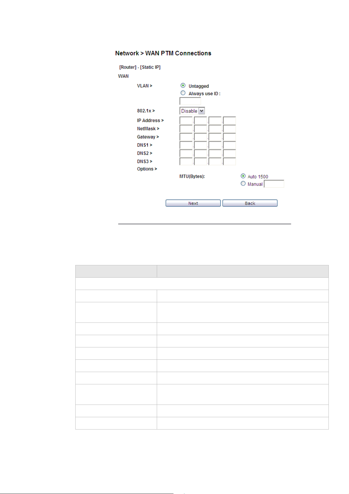
WAN PTM ConnectionsNetwork
............................................................................................................................................................................................................................................................
Figure 6-12 Static IP settings window with No LAN/WLAN Binding
Table 6-10 describes the fields of Static IP setting window with No LAN/WLAN Binding.
Table 6-10 Field descriptions
Field Description
WA N
Untagged Select this option if VLAN ID is not being used.
Always Use ID Select this option if VLAN ID is used and enter the VLAN ID
number (between 2 and 4094)
IP Address Enter the IP address provided by your ISP.
NetMask Enter the subnet mask provided by your ISP.
Gateway Enter the gateway’s IP address provided by your ISP.
DNS1/2/3 Enter the DNS IP address. They are optional
Options
MTU Select Auto to set the maximum transfer unit to the default
(1500), or select Manual to manually enter a value.
Next Click to go to next step.
Back Click to go back to previous page.
............................................................................................................................................................................................................................................................
3EQ-10422-AAAA-TCZZA
Edition 01 February 2011
6-21
Page 60

WAN PTM Co n n e c t i o nsNetwork
............................................................................................................................................................................................................................................................
DHCP Mode
If you select DHCP as the mode and click Add, the DHCP window with No LAN/WLAN
Binding opens; see Figure 6-13.
Figure 6-13 DHCP settings window with No LAN/WLAN Binding
Table 6-11 describes the fields of DHCP Mode setting window with No LAN/WLAN
binding.
Table 6-11 Field descriptions
Field Description
WA N
Untagged Select this option if VLAN ID is not being used.
Always Use ID Select this option if VLAN ID is used and enter the
VLAN ID number (between 2 and 4094)
802.1x Select Enable to enable 802.1x, or select Disable to
disable 802.1x. Please consult with your ISP for
more information.
DHCP Options
Host Name
Domain Name
Vender Class ID
Client ID
Enter the appropriate Host Name and Domain Name
provided by your ISP. If you are not sure, please
consult with your ISP for more information.
You may also need to set the Client ID or Vender
Class ID to obtain its lease from the DHCP server.
Please consult with your ISP for more information.
............................................................................................................................................................................................................................................................
6-22
3EQ-10422-AAAA-TCZZA
Edition 01 February 2011
Page 61

WAN PTM ConnectionsNetwork
............................................................................................................................................................................................................................................................
Field Description
MTU (Bytes) Enable Auto to set the maximum transfer unit to the
default (1500), or enable Manual to manually enter
a value.
Next Click to go to next step.
Back Click to go back to preview page.
PPPoE Mode
If you select DHCP as the mode and click Add, the DHCP window with No LAN/WLAN
Binding opens; see Figure 6-14.
Figure 6-14 PPPoE Mode settings window with No LAN/WLAN Binding
Table 6-12 describes the fields of PPPoE Mode setting window with No LAN/WLAN
Binding.
Table 6-12 Field descriptions
Fields Description
Wan
............................................................................................................................................................................................................................................................
3EQ-10422-AAAA-TCZZA
Edition 01 February 2011
6-23
Page 62

WAN PTM Co n n e c t i o nsNetwork
............................................................................................................................................................................................................................................................
Fields Description
Untagged Select this option if VLAN ID is not being used.
Always use ID Select this option if VLAN ID is used and enter the
VLAN ID number (between 2 and 4094)
User Name Enter the user name for the PPPoE connection.If
you are not sure, please consult with your ISP for
more information.
Password Enter the password for the PPPoE connection.If you
are not sure, please consult with your ISP for more
information.
Access Concentrator The access concentrator is optional. Please consult
with your ISP for information.
Service Name The service name is optional. Please consult with
your ISP for information.
Mode
Connect on demand: Max idle time Select this option to let the gateway connect to
Internet only when your trying to access it. If there
are no activities in the specified period (Max idle
time), gateway will disconnect the connection.
Always on Select this option to let the gateway always
connected to the Internet.
Manual Select and then click Connect to manually connect
the router to the Internet. Click Disconnect to
disconnect the connection.
Options
Authentication Mode Select the authentication mode from the drop-down
menu. Options include:
• CHAP + PAP
• Only MS-CHAP
• Only CHAP
• Only PAP
This is optional. Your ISP will provide this
information if it is necessary.
MTU (bytes) Select Auto to set the maximum transfer unit to the
default (1492), or enable Manual to manually enter
a value.
Next Click to go to next step.
Back Click to go back to previous page.
............................................................................................................................................................................................................................................................
6-24
3EQ-10422-AAAA-TCZZA
Edition 01 February 2011
Page 63
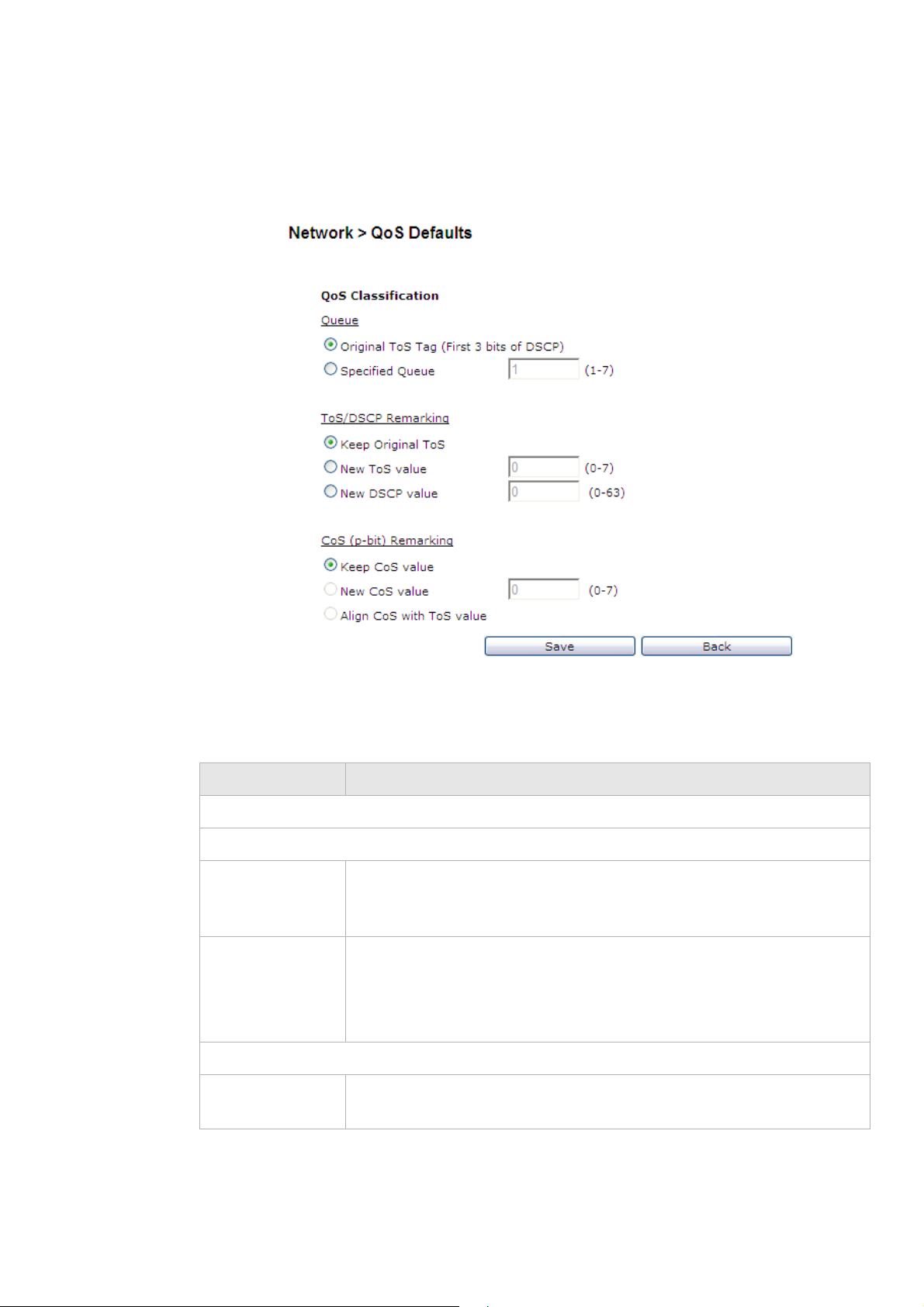
WAN PTM ConnectionsNetwork
............................................................................................................................................................................................................................................................
QoS Defaults
The QoS Defaults window enables you to configure the default QoS policy for each WAN
connection, see Figure 6-15.
Figure 6-15 QoS Defaults window
Table 6-13 describes the fields of the QoS Defaults window.
Table 6-13 Field descriptions
Field Description
QoS Classification
Queue
Original ToS Tag
(First 3 bits of
DSCP)
Specified Queue Select Specified Queue and enter a queue number (0 to 7) to which the
To S / D S C P R e m a r k i n g
Keep Original
ToS
Select Original ToS Tag to assign the queue according to the ToS value
of the packet.
network traffic will be assigned.
Note: When Specified Queue is chosen, you cannot choose Align
CoS with ToS Value.
Select Keep Original ToS to retain the original ToS value.
............................................................................................................................................................................................................................................................
3EQ-10422-AAAA-TCZZA
Edition 01 February 2011
6-25
Page 64

WAN PTM Co n n e c t i o nsNetwork
............................................................................................................................................................................................................................................................
Field Description
New ToS Value Select New Tos Value and enter a queue number (0 to 7) to assign to the
network traffic.
New DSCP Value Select New DSCP Value and enter a DSCP value (0 to 63).
CoS (p-bit) Remarking
Keep CoS Value Select Keep CoS Value to retain the original CoS value.
New CoS Value Select New CoS Value to assign CoS for network traffic.
Align CoS with
ToS Valu e
Select to align CoS with ToS value.
Note: This field can only be set if you keep Original ToS Tag in queue
setting.
Save Click to save your changes.
Back Click to return to the previous window.
............................................................................................................................................................................................................................................................
6-26
3EQ-10422-AAAA-TCZZA
Edition 01 February 2011
Page 65

7 WiFi Setup
Overview
Purpose
This chapter explains how to configure the WiFi settings for the CellPipe 7130 RG from
the WiFi setup menu.
Click the WiFi Setup drop-down menu to open the WiFi Setup menu.
Contents
This chapter covers the following topics:
WiFi Setting
The WiFi Setting window enables you to configure the common wireless and SSID
settings.
Click on
Figure 7-1.
WiFi Setting 7-1
WiFi Security 7-4
WiFi Access Filter 7-6
WiFi Setting in the WiFi Setup menu to access the WiFi Setting window; see
............................................................................................................................................................................................................................................................
3EQ-10422-AAAA-TCZZA
Edition 01 February 2011
7-1
Page 66

WiFi SettingWiFi Setup
............................................................................................................................................................................................................................................................
Figure 7-1 WiFi Setting window
Table 7-1 describes the fields of the WiFi Setting window.
Table 7-1 Field descriptions
Field Description
Common
WiFi Select Enable to turn wireless on and configure the wireless
settings. Or select Disable to turn wireless off.
Multiple SSID Click the drop-down menu and select either 1, 2, or 4 for
multiple SSIDs.
............................................................................................................................................................................................................................................................
7-2
3EQ-10422-AAAA-TCZZA
Edition 01 February 2011
Page 67

WiFi SettingWiFi Setup
............................................................................................................................................................................................................................................................
Field Description
Tx Power Enter a value between 1~100 to control the level of transmitting
signal strength.
Radio Mode Click the drop-down menu and select either b/g/n, b/g, g/n, b,
g or n for the wireless mode.
Auto Channel Select Click the drop-down menu and select On to let the wireless
access point automatically select a channel with the least
interference. Select Off to configure manually. Select Now to
set the channel automatically once.
Channel If auto channel select is off, you can manually select a channel
for the wireless access point. The default is 1.
Beacon Period Enter a beacon period in ms to determine the frequency of the
beacon to keep the network synchronized. This is optional.
DTIM Period Enter a value to set the delivery traffic indication message. The
DTIM field is a countdown field informing clients of the next
window for listening to broadcast and multicast messages.
Bandwidth Click the drop-down menu and select either 20/40Mhz or
20Mhz as the transmitting frequency for 802.11n. Select
20/40Mhz can provide double the data transmitting rate of
20Mhz.
Extension Channel 802.11n will create an extension channel to transmit data. Select
a channel from the drop-down menu to use as the extension
channel.
SSID 1 to 4
SSID Enter a SSID name (Maximum of 32 characters). The SSID is
an alphanumeric name shared by all the devices on the wireless
network. It must be unique.
Broadcast SSID Click the drop-down menu and select On to broadcast the SSID
or Off to hide your SSID.
Tx Rate Click the drop-down menu and select Auto to automatically
determine the transmission rate or select a transmission rate
(Max. 54Mbps).
IGMP Enable Enable to use IGMP or disable to turn off IGMP.
WDS
1
Click the drop-down menu and select Enable if you would like
to enter the wireless MAC of other wireless access points or
routers that are in the same WDS.
Other WDS Stations Enter the wireless MAC addresses of other wireless APs or
routers that are in the same WDS.
Apply Changes Click to save your changes.
............................................................................................................................................................................................................................................................
3EQ-10422-AAAA-TCZZA
Edition 01 February 2011
7-3
Page 68

WiFi SecurityWiFi Setup
............................................................................................................................................................................................................................................................
Notes:
1
If you enable WDS, check that all other WDS APs are enabled, configured with the same
channel, SSID, and encryption keys, and that each AP has a different LAN port IP
address.
WiFi Security
WiFi security enables you to configure the WEP, WPA, or WPA2 security settings.
Select WiFi Security in the WiFi Setup menu to access the WiFi security window; see
Figure 7-2.
Figure 7-2 WiFi Security window
Table 7-2 describes the fields of the WiFi Security settings window.
Table 7-2 Field descriptions
Field Description
WPS Enable Push Button Control or enable PIN and enter your PIN
number and click Start.
............................................................................................................................................................................................................................................................
7-4
3EQ-10422-AAAA-TCZZA
Edition 01 February 2011
Page 69

WiFi SecurityWiFi Setup
............................................................................................................................................................................................................................................................
Field Description
Authentication Select one of the following encryption methods for the wireless
network:
• Open
• Shared
• WPAPSK
• WPA2PSK
• WPAPSK/WPA2PSK Mixed
• WPA
• WPA2
Security Type Select one of the following for the security type:
• NONE
• WEP
• TKIP
• AES
• TKIP/AES Mixed
WEP
Passphrase Key Select a level of encryption (64 bits or 128 bits). Enter a
passphrase key consisting of 8 to 63 alphanumeric characters and
click Generate.
Key 1 to 4 Select either Key1, Key2, Key3, Key4. Enter a WEP key in the
respective field. The WEP key must:
• contain letters from A to F and numbers from 0 to 9
• contain 10 characters for 64 bit and 26 characters for 128 bit
encryption
WPA-PSK/WPA2PSK
Preshared Key Enter a preshared key consisting of 8 to 63 alphanumeric
characters.
802.1x
Radius Server Enter the IP address of the RADIUS server.
Radius Port Enter the port number of the RADIUS server.
Radius Key Enter the key of the RADIUS server.
Apply Changes Click to save your changes.
............................................................................................................................................................................................................................................................
3EQ-10422-AAAA-TCZZA
Edition 01 February 2011
7-5
Page 70

WiFi Access FilterWiFi Setup
............................................................................................................................................................................................................................................................
WiFi Access Filter
The WiFi Access Filter window enables you to either block or permit access for wireless
clients by MAC address.
Select WiFi Access in the WiFi Setup menu to access the WiFi Access Filter window; see
Figure 7-3.
Figure 7-3 WiFi Access Filter window
Table 7-3 describes the fields of the WiFi Access Filter window.
Table 7-3 Field descriptions
Field Description
Access Policy Select one of the following:
• Disable to turn off WiFi filtering
• Allow to permit access from the specified MAC
address.
• Deny to deny access from the specified MAC
address.
............................................................................................................................................................................................................................................................
7-6
3EQ-10422-AAAA-TCZZA
Edition 01 February 2011
Page 71

WiFi Access FilterWiFi Setup
............................................................................................................................................................................................................................................................
Field Description
MAC 1 to 32 Enter up to 32 MAC addresses to control their
access.
Apply Changes Click to save your changes.
............................................................................................................................................................................................................................................................
3EQ-10422-AAAA-TCZZA
Edition 01 February 2011
7-7
Page 72

WiFi Access FilterWiFi Setup
............................................................................................................................................................................................................................................................
............................................................................................................................................................................................................................................................
7-8
3EQ-10422-AAAA-TCZZA
Edition 01 February 2011
Page 73

8Firewall Setup
Overview
Purpose
This chapter explains how to configure the firewall for the CellPipe 7130 RG.
Click the Firewall drop-down menu to open the Firewall Setup menu.
Contents
This chapter covers the following topics:
Port Forwarding 8-1
Demilitarized Zone (DMZ) 8-3
UPnP 8-4
Layer 2 Filter 8-5
Layer 3 Filter 8-7
NAT Passthrough 8-8
URL Blocking 8-9
Content Screening 8-10
Parental Control 8-12
Port Forwarding
The Port Forwarding window enables you to control the incoming requests from the
Internet to pass through the port to your local computer, and acts as a gateway to pass your
service request using a different port or port range other than the standard port from the
Internet client to your local servers.
Note: It is recommended that port forwarding be configured with the assistance of
your ISP.
............................................................................................................................................................................................................................................................
3EQ-10422-AAAA-TCZZA
Edition 01 February 2011
8-1
Page 74
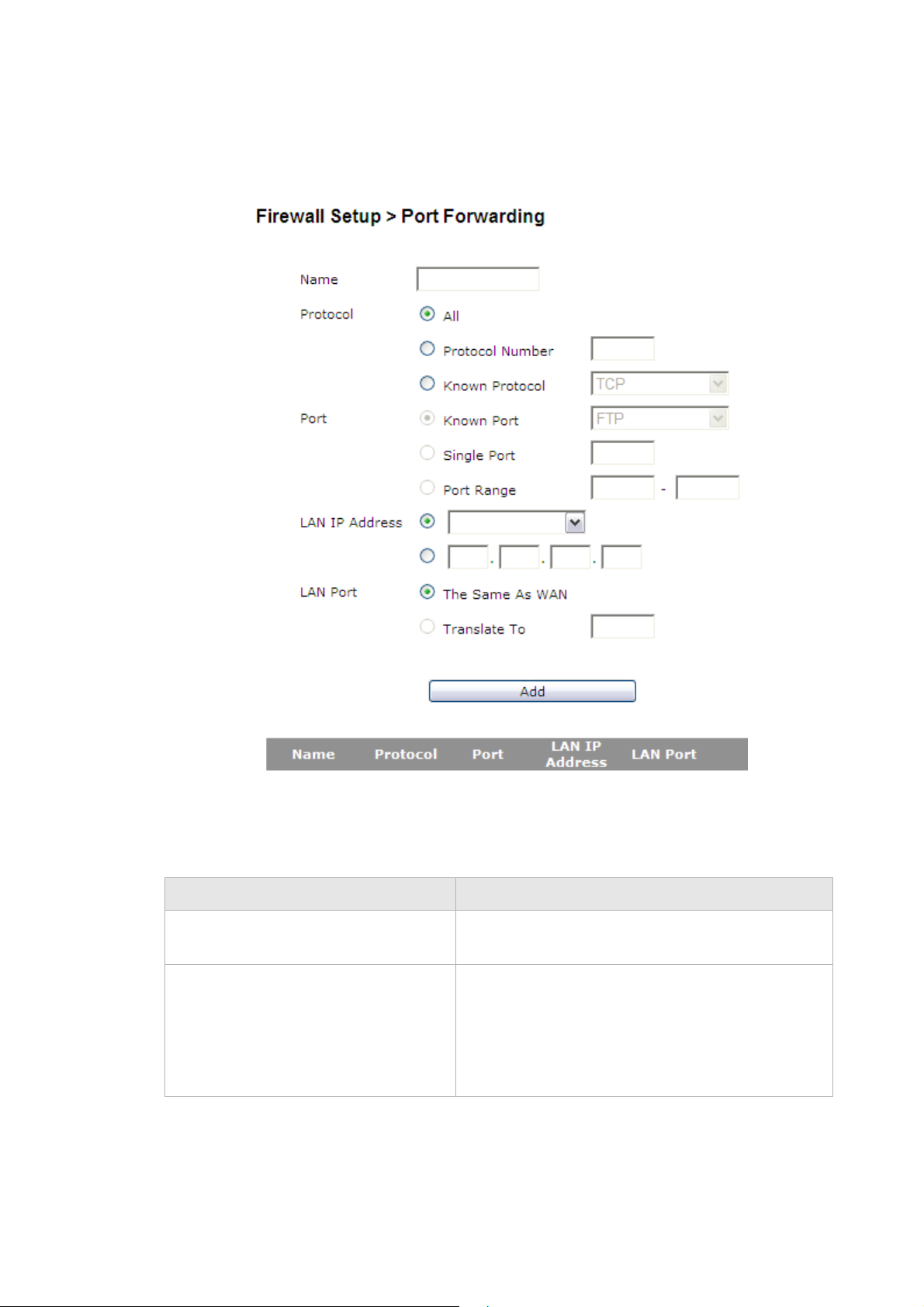
Port F orwardingFirewall Setup
............................................................................................................................................................................................................................................................
Select Port Forwarding in the Firewall Setup menu to access the Port Forwarding
window; see Figure 8-1.
Figure 8-1 Port Forwarding window
Table 8-1 describes the fields of the Port Forwarding window.
Table 8-1 Field descriptions
Field Description
Name Enter a name for the application you are hosting on
your LAN computer; for example, Real Audio.
Protocol Select the type of protocol(s) used by this
application:
• ALL
• Protocol Number
• Known Protocol
............................................................................................................................................................................................................................................................
8-2
3EQ-10422-AAAA-TCZZA
Edition 01 February 2011
Page 75

Demilitarized Zone (DMZ)Firewall Setup
............................................................................................................................................................................................................................................................
Field Description
Port Select or enter the port used by this application:
• Known Port
• Single Port
• Port Range
LAN IP Address Select the first radio button to choose a pre-
configured LAN host or select the second radio
button to enter an IP address manually.
LAN Port Select the first radio button to use the port or port
range same as the WAN or select the second radio
button enter the LAN port manually.
Apply Changes Click to save your changes.
Demilitarized Zone (DMZ)
The Demilitarized Zone window enables you to configure a single computer on your local
side exposed to the Internet. All incoming packets will be forwarded to this computer; see
Table 8-2.
Note: Use the demilitarized zone setting only if the virtual server or port range
forwarding options do not provide the level of access required for certain applications.
It is recommended that you contact your ISP for assistance.
Select Demilitarized Zone in the Firewall Setup menu to access the demilitarized zone
window; see Figure 8-2.
............................................................................................................................................................................................................................................................
3EQ-10422-AAAA-TCZZA
Edition 01 February 2011
8-3
Page 76

UPnPFirewall Setup
............................................................................................................................................................................................................................................................
Figure 8-2 Demilitarized Zone window
UPnP
Table 8-2 describes the fields of the Demilitarized Zone window.
Table 8-2 Field descriptions
Field Description
Demilitarized Zone (DMZ) Select Enable to turn on the demilitarized zone
function. Select Disable to turn it off.
DMZ Host IP Address Select the first radio button and choose a pre-
existing (or preset) LAN host or select the second
radio button to enter an IP address manually.
DMZ Timer (Option) To improve security, specify the length of time (in
seconds) during which the DMZ is active.
Apply Changes Click to save your changes.
UPnP is an open networking standard that allows peer-to-peer network connectivity
between devices. It enables software or devices, such as video game consoles, to function
properly using NAT. See Tabl e 8-3 below.
Note: It is recommended that you contact your ISP for assistance.
............................................................................................................................................................................................................................................................
8-4
3EQ-10422-AAAA-TCZZA
Edition 01 February 2011
Page 77
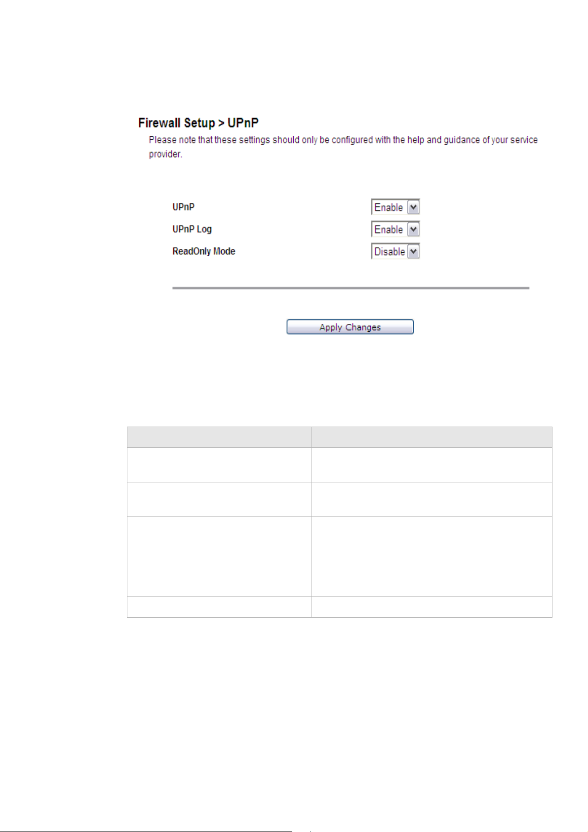
Layer 2 FilterFirewall Setup
............................................................................................................................................................................................................................................................
Select UPnP in the Firewall Setup menu to access the UPnP window; see Figure 8-3.
Figure 8-3 UPnP window
Table 8-3 describes the fields of the UPnP window.
Table 8-3 Field descriptions
Field Description
UPnP Select Enable to enable the UPnP function. Select
UPnP Log Select Enable to enable the logging activities.
ReadOnly Mode Select Enable to turn on the read-only mode. Select
Apply Changes Click to save your changes.
Layer 2 Filter
Disable to disable the UPnP function.
Select Disable to disable the logging activities.
Disable to turn off the read-only mode.
Note: In read-only mode, users are unable to
change port forwarding settings or any other UPnP
enabled application settings.
Select Layer 2 Filter in the Firewall Setup menu to access the Layer 2 Filter window; see
Figure 8-4.
............................................................................................................................................................................................................................................................
3EQ-10422-AAAA-TCZZA
Edition 01 February 2011
8-5
Page 78
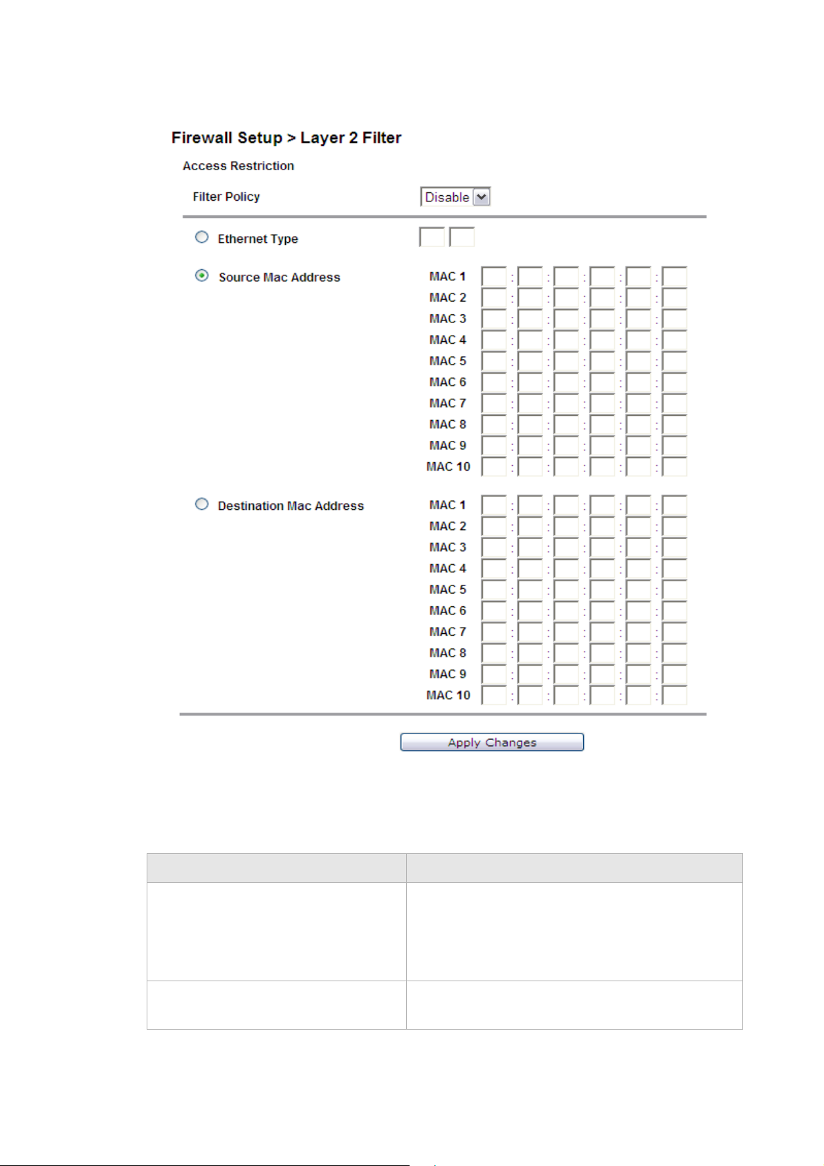
Layer 2 FilterFirewall Setup
............................................................................................................................................................................................................................................................
Figure 8-4 Layer 2 Filter window
Table 8-4 describes the fields of the Filter window.
Table 8-4 Field descriptions
Field Description
Filter Policy Select the policy for filters:
• Allow
• Deny
• Disable
Ethernet Type Select to use Ethernet Type as the filtering algorithm
and enter the applicable Ethernet Type code.
............................................................................................................................................................................................................................................................
8-6
3EQ-10422-AAAA-TCZZA
Edition 01 February 2011
Page 79
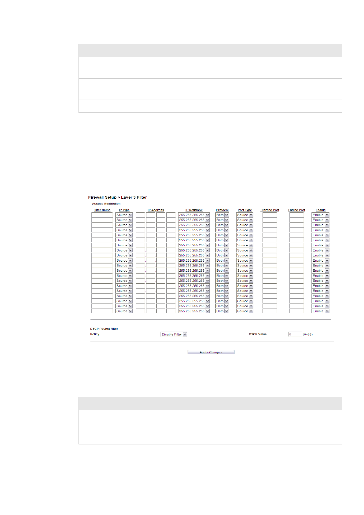
Layer 3 FilterFirewall Setup
............................................................................................................................................................................................................................................................
Field Description
Source Mac Address 1 to 10 Select and then enter the source MAC address of the
device.
Destination Mac Address 1 to 10 Select and then enter the destination MAC address
of the device.
Apply Changes Click to save your changes.
Layer 3 Filter
Select Layer 3 Filter in the Firewall Setup menu to access the Layer 3 Filter window; see
Figure 8-5.
Figure 8-5 Layer 3 Filter window
Table 8-5 describes the fields of the Filter window.
Table 8-5 Field descriptions
Field Description
Filter Name Enter a name for this filtering rule.
IP Type Select Dest (destination) or Source depending on
the how the rule is going to be used.
............................................................................................................................................................................................................................................................
3EQ-10422-AAAA-TCZZA
Edition 01 February 2011
8-7
Page 80

NAT PassthroughFirewall Setup
............................................................................................................................................................................................................................................................
Field Description
IP Address Enter the IP address of the host that you are
blocking.
IP Netmask Select the Netmask of the host that you are blocking.
Protocol Select the type protocol(s) used by this application:
• TCP
• UDP
• Both
Port Type Select Dest (destination) or Source depending on
the type of application.
Starting Port
Ending Port
Enable Select Enable to apply this filter rule or Disable to
DSCP Policy Select Disable Filter to disable the DSCP policy.
DSCP Value Enter a DSCP value between 0 and 63.
Apply Changes Click to save your changes.
NAT Passthrough
Enter the range of the ports used by this application.
turn off this filter rule.
Select Deny to deny packets that are accessing the
Internet with the specified DSCP value in IP header
or select Allow to allow packets that are accessing
the Internet with the specified DSCP value in IP
header.
The NAT Passthrough window allows you to enable or disable specific protocols from
passing through the gateway.
Select NAT Passthrough in the Firewall Setup menu to access the NAT Passthrough
window; see Figure 8-6.
............................................................................................................................................................................................................................................................
8-8
3EQ-10422-AAAA-TCZZA
Edition 01 February 2011
Page 81

URL BlockingFirewall Setup
............................................................................................................................................................................................................................................................
Figure 8-6 NAT Passthrough window
Table 8-6 describes the fields of the NAT Passthrough window.
Table 8-6 Field descriptions
Field Description
IPSec Passthrough Select Enable to allow IPSec passthrough. Select
L2TP Passthrough Select Enable to allow L2TP passthrough. Select
PPTP Passthrough Select Enable to allow PPTP passthrough. Select
Apply Changes Click to save your changes.
URL Blocking
The URL Blocking window enables you to block requests form your local computer to
access specific websites.
Select URL Blocking in the Firewall Setup menu to access the URL Blocking window;
see Figure 8-7.
Disable to disallow the IPSec passthrough.
Disable to disallow L2TP passthrough.
Disable to disallow PPTP passthrough.
............................................................................................................................................................................................................................................................
3EQ-10422-AAAA-TCZZA
Edition 01 February 2011
8-9
Page 82
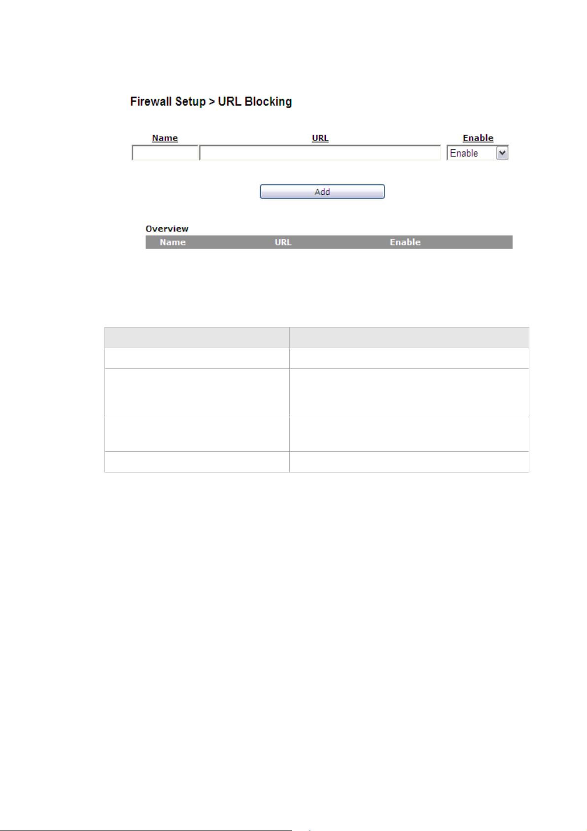
Content ScreeningFirewall Setup
............................................................................................................................................................................................................................................................
Figure 8-7 URL Blocking window
Table 8-7 describes the fields for the URL Blocking window.
Table 8-7 Field descriptions
Field Description
Name Enter a name for this URL filter.
URL Enter a URL or keyword of the URL you are
Enable Select Enable to apply this URL filter. Select
Add Click to add the URL in blocking rule.
Content Screening
The Content Screening window lets you configure keywords to screen website content. If
the keywords appears in the website content and content screening is enabled, firewall will
block user from accessing this website.
Select Content Screening in the Firewall Setup menu to access the Content Screening
window; see Figure 8-8.
blocking. If the keyword is too general, you might
inadvertently block other websites.
Disable to turn off this URL filter.
............................................................................................................................................................................................................................................................
8-10
3EQ-10422-AAAA-TCZZA
Edition 01 February 2011
Page 83

Content ScreeningFirewall Setup
............................................................................................................................................................................................................................................................
Figure 8-8 Content Screening window
Table 8-8 describes the fields for the Content Screening window.
Table 8-8 Field descriptions
Field Description
Content Screening Select Enable to apply content screening content
and block websites that have configured keywords
in their contents. Select Disable to disable content
screening.
Key Words Enter a keyword you are blocking. If the keyword is
too general, you might inadvertently block other
websites. Type in only one keyword, if you want to
screen multiple keywords, add them in separate
rules. Maximum number of keywords allowed are
254.
Index The index of rule. The index is created by system.
Add Click to add the keyword in content screening rule.
Edit Click to edit the keyword to the content screening
rule.
Delete Click to delete the keyword to the content screening
rule.
............................................................................................................................................................................................................................................................
3EQ-10422-AAAA-TCZZA
Edition 01 February 2011
8-11
Page 84
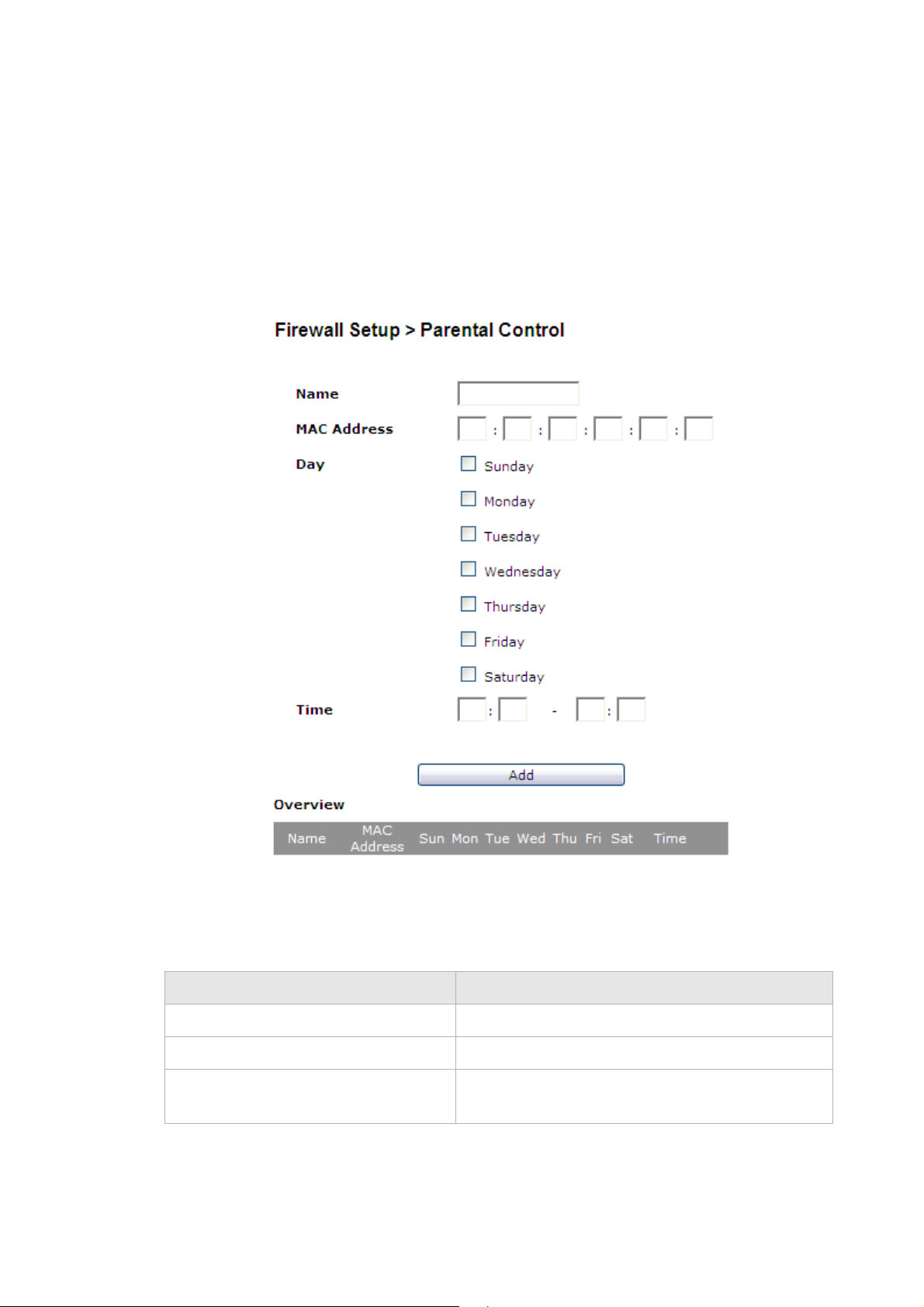
Parental ControlFirewall Setup
............................................................................................................................................................................................................................................................
Parental Control
The Parental Control window enables you to limit your computer’s Internet connection
based on the time and day of the week.
Select Parental Control in the Firewall Setup menu to access the Parental Control
window; see Figure 8-9.
Figure 8-9 Parental Control window
Table 8-9 describes the fields for the Parental Control window.
Table 8-9 Field descriptions
Field Description
Name Enter an appropriate name for your rule.
Mac Address Enter the MAC address of the client computer.
Day Check the days you want to limit the client’s Internet
connection.
............................................................................................................................................................................................................................................................
8-12
3EQ-10422-AAAA-TCZZA
Edition 01 February 2011
Page 85

Parental ControlFirewall Setup
............................................................................................................................................................................................................................................................
Field Description
Time Enter a time period (in hours and minutes) to limit
the Internet connection.
Add Click to add rule in Parental control.
............................................................................................................................................................................................................................................................
3EQ-10422-AAAA-TCZZA
Edition 01 February 2011
8-13
Page 86

Parental ControlFirewall Setup
............................................................................................................................................................................................................................................................
............................................................................................................................................................................................................................................................
8-14
3EQ-10422-AAAA-TCZZA
Edition 01 February 2011
Page 87

9 Advanced Setup
Overview
This chapter explains how to configure the advanced settings of the CellPipe 7130 RG
such as the route setting, DNS, dynamic DNS, system log, IGMP settings and 802.1x.
Click the Advanced Setup drop-down menu to open the Advanced Setup menu.
Contents
This chapter covers the following topics:
Route Setting 9-1
DNS Settings 9-3
Dynamic DNS 9-4
System Log 9-5
IGMP Proxy/Snooping 9-6
802.1x Config 9-7
Route Setting
The Route Setting window enables you to configure static and dynamic routes for routing
packets from one network to another network.
Select Route Setting in the Advanced Setup menu to access the Route Setting window;
see Figure 9-1.
............................................................................................................................................................................................................................................................
3EQ-10422-AAAA-TCZZA
Edition 01 February 2011
9-1
Page 88

Route SettingAdvanced Setup
............................................................................................................................................................................................................................................................
Figure 9-1 Route Setting window
Table 9-1 describes the fields of the Route Setting window.
Table 9-1 Field descriptions
Field Description
Static Route Static routing enables you to configure a pre-determined path that
network traffics need to travel to reach other network or host.
IP Destination Enter the IP address of the destination network.
IP Netmask Select the subnet mask of the destination network.
Gateway Enter the IP address of the gateway for the destination network.
Metric In order to determine the best route, a value is used to specify the
cost of the route (the metric value). Enter the metric value in the
metric field. IP routing uses hop count as measurement of the
metric.
Interface Select LAN or WAN interface. The packets sent to the addresses of
the destination IP address are sent through this interface. However,
for the WAN interface it will depends on the WAN configuration.
............................................................................................................................................................................................................................................................
9-2
3EQ-10422-AAAA-TCZZA
Edition 01 February 2011
Page 89

DNS SettingsAdvanced Setup
............................................................................................................................................................................................................................................................
Field Description
Dynamic Route (WAN) Select Enable to use dynamic routing instead of static. Dynamic
routing enables the router to adapt to changes in the network and
exchange rating table with other router(s). Select Disable to turn
off dynamic routing.
Apply Changes Click to save your changes.
DNS Settings
The DNS Settings window enables you to configure the domain name and IP address of
the domain name.
Note: You can set up to 64 entries.
Select DNS Settings in the Advanced Setup menu to access the DNS Settings window;
see Figure 9-2.
Figure 9-2 DNS Settings window
Table 9-2 describes the fields of the Dynamic DNS window.
Table 9-2 Field descriptions
Field Description
Domain Name Enter the domain name to which you want to
connect.
IP Address Enter the IP address of the Static DNS.
Add Click to add the DNS settings and save your
changes.
............................................................................................................................................................................................................................................................
3EQ-10422-AAAA-TCZZA
Edition 01 February 2011
9-3
Page 90
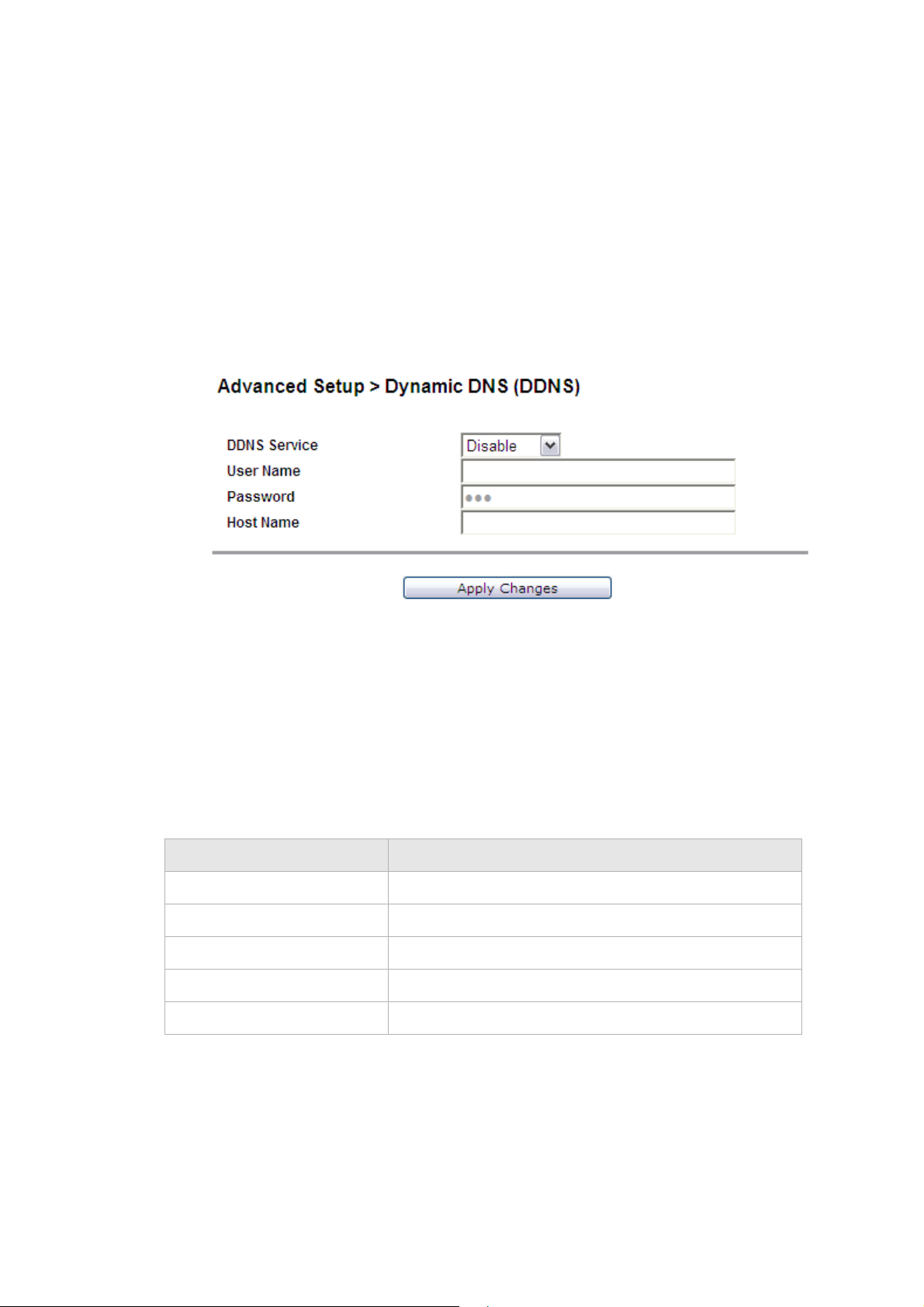
Dynamic DNSAdvanced Setup
............................................................................................................................................................................................................................................................
Dynamic DNS
The Dynamic DNS (DDNS) window enables you to configure your registered domain
name with a dynamic IP address.
Note: Before you can use this feature, you need to sign up a DDNS service at one of
the supported DDNS service providers; see DynDNS.org or ChangeIP.com.
Click on Dynamic DNS in the Advanced Setup menu to access the dynamic DNS window;
see Figure 9-3.
Figure 9-3 Dynamic DNS window
Table 9-3 describes the fields of the Dynamic DNS window.
Table 9-3 Field descriptions
Field Description
DDNS Service If you have signed up a DDNS, select the DDNS service.
User Name Enter the username of your DDNS account.
Password Enter the password of your DDNS account.
Host Name Enter the host name.
Apply Changes Click to save your changes.
............................................................................................................................................................................................................................................................
9-4
3EQ-10422-AAAA-TCZZA
Edition 01 February 2011
Page 91

System LogAdvanced Setup
............................................................................................................................................................................................................................................................
System Log
The System Log window enables you to view the system logs and to send them to a
remote system log server.
Click on System Log in the Advanced Setup menu to access the system log window; see
Figure 9-4.
Figure 9-4 System Log window
Table 9-4 describes the fields of the System Log window.
Table 9-4 Field descriptions
Field Description
Log Size (Lines) Select the number of lines to display in your log.
Remote Logging Select LAN or WAN for the remote logging server. Select
Disable to turn off remote logging.
Remote Server Enter the IP address of the remote logging server.
Apply Changes Click to save your changes to view the log.
If you are configuring remote logging, click Apply
Changes after changing the remote logging and remote
server fields.
Time The time that the action was performed.
Module The type of module the action involved.
............................................................................................................................................................................................................................................................
3EQ-10422-AAAA-TCZZA
Edition 01 February 2011
9-5
Page 92

IGMP Proxy/SnoopingAdvanced Setup
............................................................................................................................................................................................................................................................
Field Description
Level The level of logging activity:
• Info
• Error
• Debug
Message The details of the action that was performed.
IGMP Proxy/Snooping
The IGMP Setting window enables you to setup LAN-side IGMP protocol supporting
which enable LAN-side user to receive multicast traffic.
Click on IGMP Settings in the Advanced Setup menu to access the system log window;
see Figure 9-5.
Figure 9-5 IGMP Proxy/Snooping window
Table 9-5 describes the fields of the System Log window.
............................................................................................................................................................................................................................................................
9-6
3EQ-10422-AAAA-TCZZA
Edition 01 February 2011
Page 93
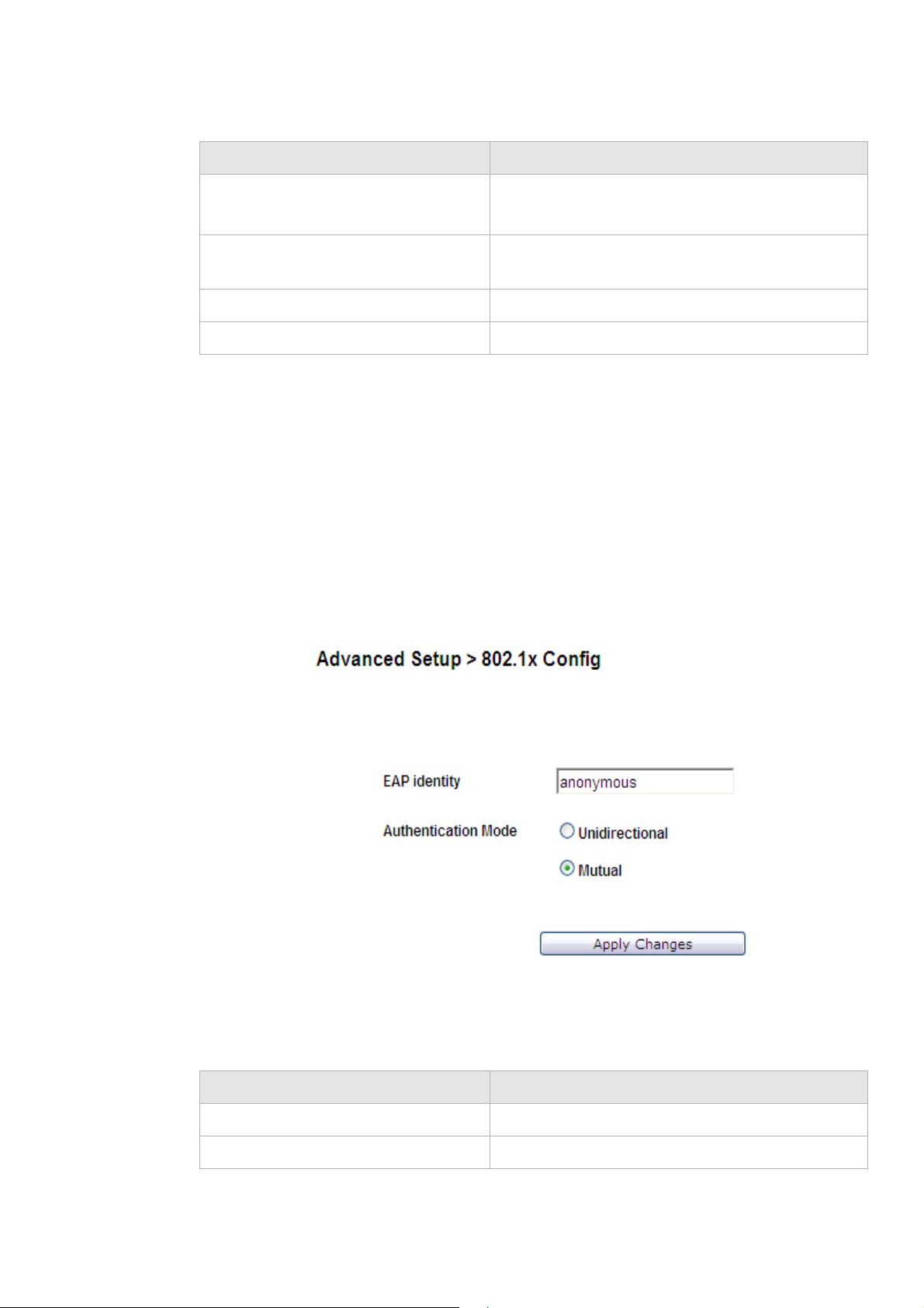
802.1x ConfigAdvanced Setup
............................................................................................................................................................................................................................................................
Table 9-5 Field descriptions
Field Description
IGMP Enable Select Enable to allow IGMP support.
Select Disable to disable IGMP support.
Port Enable Enable/Disable IGMP support for each individual
LAN port.
IGMP Aging Time Enter the IGMP aging time in seconds.
Apply Changes Click to save your changes.
802.1x Config
The 802.1x Config window enables you to setup the 802.1x configuration. 802.1x is an
authentication mechanism for clients connecting to an IEEE 802 network such as
Ethernet (access) networks and 802.11 (public) wireless LANs.
Click on 802.1x Config in the Advanced Setup menu to access the 802.1x Config
window; see Figure 9-6.
Figure 9-6 802.1x Config window
Table 9-6 describes the fields of the 802.1x Config window.
Table 9-6 Field descriptions
Field Description
EAP identify Enter the EAP identity.
Authentication Mode Select Unidirectional or Mutual support for each.
............................................................................................................................................................................................................................................................
3EQ-10422-AAAA-TCZZA
Edition 01 February 2011
9-7
Page 94

802.1x ConfigAdvanced Setup
............................................................................................................................................................................................................................................................
Field Description
Apply Changes Click to save your changes.
............................................................................................................................................................................................................................................................
9-8
3EQ-10422-AAAA-TCZZA
Edition 01 February 2011
Page 95

10 QoS PTM Setup
Overview
This chapter explains how to configure the QoS settings via PTM. QoS is the ability to
provide better service to selected applications and data flows.
Click the QoS PTM Setup drop-down menu to open the QoS PTM Setup menu.
Contents
This chapter covers the following topics:
QoS Overview 10-1
QoS Scheduler 10-2
QoS Policy 10-4
QoS Phone 10-7
QoS ALG 10-9
QoS Defaults 10-11
QoS MAC 10-13
QoS Overview
The QoS overview window allows you to see all current QoS settings.
Select QoS Overview in the QoS PTM Setup menu to access the QoS overview window;
see Figure 10-1.
............................................................................................................................................................................................................................................................
3EQ-10422-AAAA-TCZZA
Edition 01 February 2011
10-1
Page 96
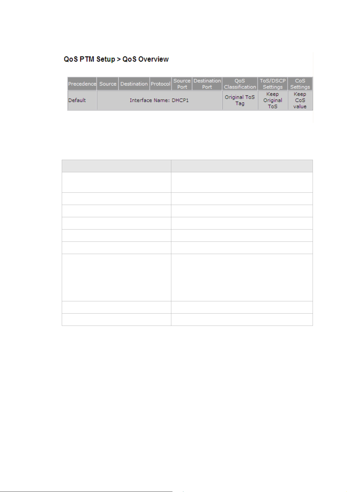
QoS SchedulerQoS PTM Setup
............................................................................................................................................................................................................................................................
Figure 10-1 QoS Overview window
Table 10-1 describes the fields of the QoS overview window.
Table 10-1 Field descriptions
Field Description
Precedence The Precedence presents the priority of each QoS
rule. (Precedence 1 is the highest priority.)
Source IP address of source host.
Destination IP address of destination host.
Protocol The protocol type of this QoS rule.
Source Port Port number of source host.
Destination Port Port number of destination host.
QoS Classification The classification of this QoS rule:
ToS/DSCP Setting TOS/DSCP marking setting for incoming traffic.
CoS Setting CoS (class of service) setting of this QoS rule.
QoS Scheduler
• Original ToS Tag - assign the queue according
to the incoming traffic ToS value.
• Specified Queue - incoming traffic will
assign a specific queue (0 to 7).
The QoS Scheduler window allows you to enable and disable the scheduler protocol and
determine the upstream bandwidth.
Select QoS Scheduler in the QoS PTM Setup menu to access the QoS scheduler window;
see Figure 10-2.
............................................................................................................................................................................................................................................................
10-2
3EQ-10422-AAAA-TCZZA
Edition 01 February 2011
Page 97

QoS SchedulerQoS PTM Setup
............................................................................................................................................................................................................................................................
Figure 10-2 QoS Scheduler window
Table 10-2 describes the fields of the QoS Scheduler window.
Table 10-2 Field descriptions
Field Description
QoS Enable Select Enable to activate the QoS scheduler. Select
Disable to turn off the QoS scheduler.
Scheduler Type The QoS scheduler type is either:
• Strict Priority - Strict Priority scheduling
delivers high priority(7.Urgent queue is the
highest) traffic first and then lower priority
traffic when higher ones are empty.
• Min - Max Bandwidth - Min - Max Bandwidth
scheduling to specify the minimum and
maximum bandwidth for each queue.
7. Urgent Specify the minimum and maximum bandwidth for
the Urgent queue.
6. Real Time Specify the minimum and maximum bandwidth for
the Real Time queue.
5. High Specify the minimum and maximum bandwidth for
the High queue.
............................................................................................................................................................................................................................................................
3EQ-10422-AAAA-TCZZA
Edition 01 February 2011
10-3
Page 98

QoS PolicyQoS PTM Setup
............................................................................................................................................................................................................................................................
Field Description
4. Low Specify the minimum and maximum bandwidth for
the Low queue.
3. Premium Specify the minimum and maximum bandwidth for
the Premium queue.
2. Critical Specify the minimum and maximum bandwidth for
the Critical queue.
1. Medium Specify the minimum and maximum bandwidth for
the Medium queue.
Apply Changes Click to save your changes.
QoS Policy
The QoS Policy window enables you to group upstream traffic into data flows according
to the source address, destination address, source port, and destination port.
Select QoS Policy in the QoS PTM Setup menu to access the QoS Policy window; see
Figure 10-3.
............................................................................................................................................................................................................................................................
10-4
3EQ-10422-AAAA-TCZZA
Edition 01 February 2011
Page 99

QoS PolicyQoS PTM Setup
............................................................................................................................................................................................................................................................
Figure 10-3 QoS Policy window
Table 10-3 describes the fields of the QoS Policy window.
Table 10-3 Field descriptions
Field Description
Source
IP Address Select the radio button and enter the IP address of the source host.
............................................................................................................................................................................................................................................................
3EQ-10422-AAAA-TCZZA
Edition 01 February 2011
10-5
Page 100

QoS PolicyQoS PTM Setup
............................................................................................................................................................................................................................................................
Field Description
Netmask Select the subnet mask of the source host.
Interface Select the radio button and select a connection to configure its QoS policy.
MAC Address Select the radio button and enter the MAC address.
Destination
IP Address Enter the IP address of the destination host.
Netmask Select the subnet mask of the destination host.
Protocol Click Select Protocol to choose a protocol.
Source Port Enter the range of source ports for this QoS policy.
Destination Port Enter the range of destination ports for this QoS policy.
QoS Classification
Queue Select one of the following:
• Original ToS Tag to assign the queue according to the incoming ToS
value.
• Specified Queue and enter a queue number (0 to 7) to assign to the
incoming traffic.
ToS/DSCP
Remarking
Select one of the following:
• Keep Original ToS/DSCP to retain the original value.
• New ToS Value and enter a queue number (0 to 7) to assign to the
incoming traffic.
• New DSCP Value and enter a DSCP value (0 to 63).
CoS (p-bit)
Remarking
Select one of the following:
• Keep CoS Value to retain the original value.
• New CoS Value to set a new CoS value for incoming traffic.
• Align CoS with ToS value to set CoS same as the ToS value for
incoming traffic.
Add Click to add the policy and save your changes.
Overview
Target Upstream or Downstream. Target 1 is the highest priority.
Source IP IP address of the source host.
Netmask Subnet mask of the source IP address.
Source Port Port number of the source host.
Destination IP IP address of the destination host.
Netmask Subnet mask of the destination IP address.
Destination Port Port number of the destination host.
............................................................................................................................................................................................................................................................
10-6
3EQ-10422-AAAA-TCZZA
Edition 01 February 2011
 Loading...