

Page 1

ks are property of their respective
, implied or expressed, including, but not limited to, the implied warranties
Lucent. No part of its contents may be used,
www.alcatel
CellPipe 7130 RG 1Ez.N0001
2
Alcatel, Lucent, Alcatel-Lucent, Alcatel-Lucent Logo, and Cellpipe are trademarks of Alcatel-Lucent. All trademar
owners,
The information presented is subject to change without notice. Alcatel-Lucent assumes no responsibility for inaccuracies contained herein.
Alcatel-Lucent provides this documentation without warranty of any kind
of merchantability and fitness for a particular purpose.
Copyright © 2010 Alcatel-Lucent. All rights reserved.
Security statement
In rare instances, unauthorized individuals make connections to the telecommunications network through the use of remote access features. In
such an event,
applicable tariffs require the customer to pay all network charges for traffic. Alcatel-Lucent cannot be responsible for such charges and will not
make any
allowance or give any credit for charges that result from unauthorized access.
IMPORTANT NOTICE: This document contains confidential information that is proprietary to Alcatelcopied,
disclosed or conveyed to any party in any manner whatsoever without prior written permission from Alcatel-Lucent.
-lucent.com
Page 2

T
able of Contents
T
able
of
C
o
n
t
e
n
ts
Preface.....................................................
............................
2
Ethernet Auto Provision
..........................................................
.22
Pro
du
ct.Overview.
..............................................................
4
AP/Bridge
.Mode.
............................................
..................
11
C
onfigu
ration
.
...................................................................
14
Trademarks
P
ack
S
yst
em R
Intr
oduc
Features............................................................................................ 6
Hardware Over
C
LEDs ........................................................................................... 8
I
nstalla
tion.......................................................................... 9
Wireless I
..................................................................................... 2
age Cont
onnec
ents
......................................................................... 4
equir
ements ................................................................. 4
tion ................................................................................... 5
view ..................................................................... 7
tions ........................................................................... 7
nstalla
tion C
onsiderations
....................................
10
S
etting
up
WPS
............................................................................
22
One T
ouch AP C
Web-based C
Operating Mode .........................................................................
onfiguration
onfiguration U
..................................................
tility
..........................................
13
14
15
Page 3

Sec
tion 1 - Product Overview
P
ac
k
age
C
o
n
t
e
n
ts
CellP
ipe 7130 RG 1Ez.N0001 Wireless Video Bridge
Ethernet C
able
Power A
dap
t
er CD-ROM
with
User M
anual
Note: Using a power supply with a different voltage than the one included with the 1Ez.N0001 Video Bridge w
ill cause damage and void the
w
S
y
s
t
em
R
equi
r
eme
n
ts
• Computers with Window
s®, Macintosh®, or Linux-based operating systems with an installed Ethernet adapter
arranty for
• Internet Explorer V
this
pr
oduct.
ersion 6.0 or higher, Firefox
3.0 or higher, Safari
3.0 or higher, or
Chr
ome 2.0 or higher
Page 4

Sec
tion 1 - Product Overview
I
n
trodu
c
tion
Combines award winning access point features and
802.11n wireless technology to provide the best wireless performance.
TOTAL.
SECU
RITY
TOTAL.COVERAGE
ULTIMATE.
PERFOR
M
ANCE
wi
er
TOTAL.NETW
ORK
.
SECURI
T
Y
t
best
TOTAL.PERFORMANCE
The
most c
omplete
Provides greater
CellPipe 7130 RG 1Ez.N0001
r
eless c
music,
video, print
and share y
(QoS) engine that
wir
onnec
tion (also faster than a 100Mbps wired Ethernet c
our high-speed Internet acc
set
of
security features
eless signal rates
ers,
and network stor
keeps dig
including WPA2 and MAC A
even at
far
ther distances for best
is a 802.11n c
ital
phone calls (VoIP) and online gaming smooth and r
ompliant
age thr
ess with every
device
that
oughout your home. Connect
one on the network. In
ddr
ess Contr
-in-
class W
deliv
ers r
eal world perfor
onnec
tion). Create a secure wir
ol to
protect your network
hole Home Coverage
mance of up to 13x faster
eless network to share
the
CellPipe 7130 RG 1Ez.N0001
addition, this Wireless Br
esponsive,
providing a
against outside in
.
than an 802.11g
photos, files,
V
ideo Br
idge includes a Q
better Inter
net e
truders
idge to a rout
uality of Servic
xperience.
.
e
The
CellPipe 7130 RG 1Ez.N0001
from over the wir
possible encr
eless network or from the Internet.
yption
method, regar
Wireless Bridge supports all of the latest wireless security features to prevent unauthorized a
dless
of your client
Support for WPA and WEP standards
devices.
ensure
that you
’ll be able to
use the
ccess, be
i
Page 5

Sec
tion 1 - Product Overview
F
e
a
tu
r
es
•.Faster.Wireless.Networking.-
capabili
•.Advanced.Firewall.Features.-.
The Web-based user interface displays advanced network management features including
•.WPS.PBC-.
(Wi-Fi Protected Setup Push Button Configuration) Push Button Configuration is a button that can be pressed
•.WPS
.
PIN
.-.
(Wi-Fi Protected S
etup
Personal
Identification
Number)
A
PIN
is a
unique
number
that
can be used
to add
The
cellPipe 7130 RG 1Ez.N0001 provides up to 300 Mbps* wireless connection with other
802.11n wirele
ss
clients. T
his
allows users to
performance of this 802.11n wireless access point gives you the freedom of wireless networking at speeds 13x faster than
802.11g.
Content F
to
add the device to an e
a physical button is
T
his easy setup
another WPS enabled device. A PC is no longer needed to log into
par
ticipate in real-time ac
iltering,
which allows easily applied content filtering based on MAC A
placed on the side
method
tivities online,
xisting network or to create a
of
the device.
allows you to form a
secured
such as video str
new network. A virtual button
wir
eless link
eaming,
between the
the Web-based inter
online gaming,and real-time audio. The
ddr
CellPipe 7130 RG 1Ez.N0001 and
ess.
can be used on the utility
face.
while
the acc
ess
point to an e
the acc
ess
point. For extra security, a
A
dministrator (“admin”
xisting network or to create a
new PIN can be generated. You
acc
oun
t)
can change or r
eset the PIN.
new network. The
can r
default PIN may be
estore the default PIN at
printed on
any
the bott
time.
om
of
Only the
Page 6
Sec
tion 1 - Product Overview
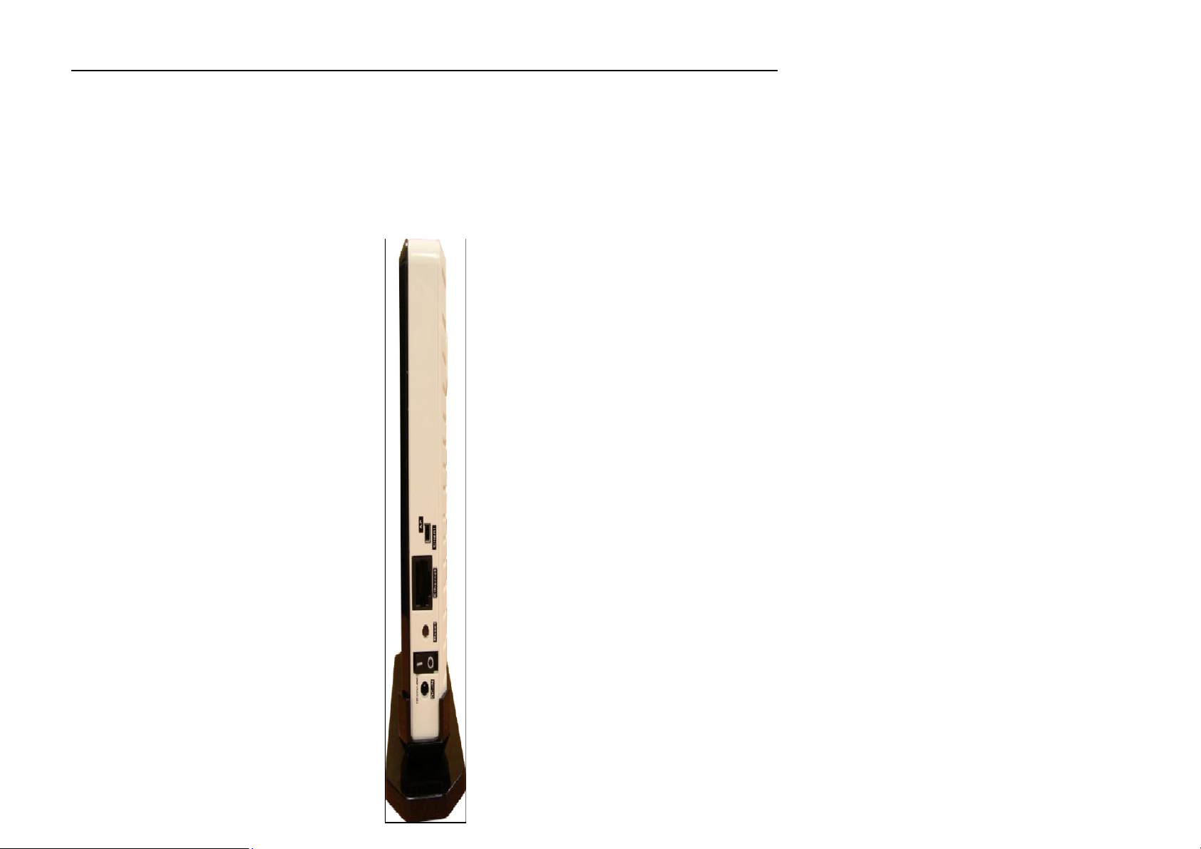
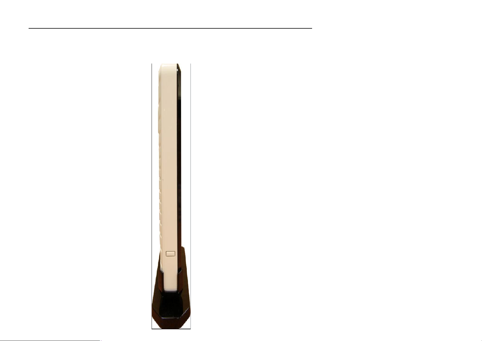
Ha
r
d
w
a
r
e
O
v
e
r
vi
e
w
C
onnec
tions
Page 7
Sec
tion 1 - Product Overview
LEDs
Page 8

Sec
tion 2 - I
nstall
a
tion
I
nstall
a
tion
T
his section
will w
alk you thr
ough
the install
a
tion
process. Placeme
nt of
the CellPipe 7130 RG 1Ez.N0001
is very impo
r
ta
Do
not place
Wall mounting
Pre-Requirements
•
Anchors
•
Screws
•
Drill & Drill bit
the
CellPipe 7130 RG 1Ez.N0001
in an
enclosed area such as a closet,
cabinet, or in
the a
ttic or garage
.
1. Locate a high position on the wall that is free of obstructions and insert two screws in
the wall 5 cm (2 in.) apart. Do not insert the screws all the way into the wall.
Important! Make sure that the screws are securely fixed to the wall and strong
enough to hold the weight of the CellPipe 7130 RG (re commended screw type and
size: Nylon wall plug [T8x25mm] and screws [T3.5x16mm]).
2. Align the holes on the back of the CellPipe 7130 RG with the screws on the wall and
then hang the CellPipe 7130 RG on the screws.
Stand-up mounting
Snap the cradle into the holes located on the side of the CellPipe 7130 RG and then place
it on a desk so that LEDs are visible.
Page 9

Sec
tion 2 - I
nstall
a
tion
W
ireless
Install
a
tion
C
onside
r
a
tions
y
maximizing
wir
eless
range
is to follow these
basic
guidelines:
1. Keep the number of walls and ceilings between the The
CellPipe 7130 RG 1Ez.N0001
access point and other
2. Be aware of the direct line between network devices. A wall that is 1.5 feet thick (0.5 meters), at a
)
or
3. Building
Materials make
a
difference. A
solid
metal
door
or
aluminum
studs
may have a neg
ative effect on
ough
(fish
4. Keep
your produ
ct away (at least
3-6 feet or 1-2 meters) from
electrical devices or applian
ces that
gene
rate RF
The CellPipe 7130 RG 1Ez.N0001
any
where
within the
loca
tion
of walls, ceilings,or other objects
depending on the t
network devices to a minimum
P
osition y
45-degree angle appears to be almost 3 feet (1 meter) thick. At a 2-degree angle it looks over 42 feet (14 meters
thick! P
better rec
operating r
ypes
of materials and backg
our devices so
osition devices so
eption.
that the number
wir
eless acc
ange
.
that
ess
of your wir
that
Each w
all or c
the signal will travel
point
lets you
eless network. Keep in
the wir
eless sig
round RF (r
eiling can r
of walls or c
acc
ess y
nals must pass thr
adio fr
equency)
educe your adapt
eilings is minimized.
str
aight
our network
mind, how
noise in y
thr
ough a w
using a wir
ever,
ough, may limit the r
our home or business. The key to
er’s range fr
all or c
eiling (instead
eless c
that
the number,
om 3-90 f
onnec
ange. Typical r
eet (1-30
of at an angle) f
tion fr
thick
met
om virtually
ness and
anges v
ers.)
ar
r
ange. Try to position acc
dryw
all or open doorways. Mater
tanks),
noise.
mirrors,
ess
points, wir
file cabinets, br
eless acc
ials and objects
ick,
and c
oncrete
ess
points, and c
such as glass,
will degr
ade y
omput
steel,
our wir
ers so that
metal, walls with insula
eless signal.
the signal passes thr
tion, water
Page 10

Sec
tion 2 - I
nstall
a
tion
AP/Bridge
M
ode
D
epending
on how you want to use y
our CellPi
pe 7130 RG 1Ez.N0001
will determine
which
mode
you use. T
his section
will help
AP
.
M
o
de
Bridge
.
M
o
de
-
Router
idge/AP
If you want to wirelessly connect multiple Ethernet enabled devices such as game consoles, media players, or network attached
you figure
out
If you already have a wired or
you
will need to
move
the switch on
wir
eless r
outer, and want to
the back panel
Wired PC 11 N
add an acc
of
the
CellPipe 7130 RG 1Ez.N0001 to “AP” (for
WIRELE S S
615
Gigabit
ess
point to c
DIR
1Ez.N0001
Wireless Br
DAP-1420
onnect your wir
DA P-15 2 2
eless clients to y
5GH
z).
our network,
storage devices you will need to
move
the switch on
the back panel
of
the
CellPipe 7130 RG 1Ez.N0001 to “
Client” (Br
idge).
Page 11

Sec
tion 2 - I
nstall
a
tion
Create.a.Full.M
edia
B
and
.
(5G
Hz.wir
eless)
.Network
ediaBand
”
the
RO UT ER
G AM E
D AP-
1 5 2 2
D AP-
152 2
1E z. N0 0 01
1Ez.N0 0 0 1
NE TW O RK
NETW O RK
DV R WI R ED PCDIGITAL
If you have two
t
echnology you
The
sec
ond Wir
switch on
eless Br
the back panel to “Client.”
CellPipe 7130 RG 1Ez.N0001
will need to c
onnect
idge will
WI RE LES S
11 N
G IG ABIT
one Wireless Br
need to be
DIR - 61 5
WI R ELE SS BRI DGE/AP
placed next to y
devices
and want to create a wir
idge to your r
our E
WI R EL E S S BR IDGE/AP
outer
thernet
eless network
and move
the switch on
-enabled devices
CO NSO LE
and you
TV VI EW ER
with full M
the back panel to “AP.
will need to
move
MED IA
PLA
YER
Page 12

Sec
tion 2 - I
nstall
a
tion
O
ne
T
ouch
AP
C
onfigu
r
a
tion
T
his feature
makes
the Wir
eless
Acc
ess Point to have
the ability to ex
change/lea
rn
the Wir
eless
Pr
ofile
fr
om
another
Wireless
1. Press the
WPS
.
button
on y
our Router or Acc
ess Point. WPS
LED
will flash
on
and
off. 2. Pr
ess
WPS
.Push
.
Button
on the 1Ez.N0001
and
hold
it for 5 second
s.3. W
hen
One
click
AP
setup
is comple
te, y
our 1Ez.N0001
will have
the same
Wireless
settings
as your e
xisting
Router or AP.
R
out
er/Access P
oint.
Page 13

Sec
tion 3 - C
onfigu
ration
C
onfigu
r
a
tion
T
his section
will show you how to c
onfigu
re your CellPipe 7130 RG 1Ez.N0001
access point using
the web-based
configu
ration
W
e
b
-
based
C
onfi
gu
r
a
tion
Utili
t
y
To access the configuration utility, open a web browser
Enter
admin
for
the user
name
and
the pass
word. If you get a P
age
Cannot
be
Displ
ayed error,
please
refer to
such as Internet Explorer and enter h
in the addr
the T
ess field.
roubleshooting sec
tion for
ttp://192.168.2.254
assistance.
Page 14

Sec
tion 3 - C
onfigu
ration
O
pe
r
a
ting
M
ode
Click
Operation.Mode
to view your device’s operation
mode.
Page 15

Sec
tion 3 - C
onfigu
ration
Ne
t
w
ork
S
ettings
E
ther
net Port
S
elect the E
thernet port mode
to suit y
our E
thernet c
onne
c
tion. Obtain
an
ess
Check
the box to
obtain
an IP
address
Use
the
IP
Default
Check
the box to
use a manuall
y-set IP address.
VLAN
S
elect to
enable
tr
anspa
rent
VLAN.
Mode:
IP addr
aut
oma
tically
:
aut
oma
tically.
f
ollo
wing
addr
ess: IP
A
ddr
ess:
Subnet M
Gateway
DNS Serv
Transparen
IP addr
ess that was set manually
ask
:
Subnet mask that was set manually.
:
D
efault gateway
er:
DNS server.
t
.
.
Page 16

Sec
tion 3 - C
onf
igura
tion
W
ireless
S
ettings
SSID:
When you are browsing for available wireless
Securi
ty Mode: Choose
the secu
rity
mode
you want to use from
D
isable
- S
elect if you don’t want to enable
any
networks, this is the name that will appear in the list.
the f
ollo
wing
five
options.
security (not recommended).
Open.WEP
S
hared.WEP
WPA-.Personal
WP
A2-.P
ersonal
Page 17

Sec
tion 3 - C
onfigu
ration
WPS
S
ettings
Choose
one of the two WPS
secu
rity
option
s. Start WPS
PBC:
Click
to start WPS
push
-
button c
onfigu
ration.
Start
WPS
PIN: Enter
the WPS
PIN of the device. Sec
Page 18

tion 3 - C
onfigu
ration
Site Su
rvey
S
can: Click
to scan
for Access Points in range.
Sec
Page 19

tion 3 - C
onfigu
ration
R
emo
te
M
anageme
nt
Enable
UPnP:
Check
the box to
enable
UPnP. Base Port: Enter the number
of
the base
port. Enable
NTP:
NTP
er:
NTP
er:
Check
the box to
enable
NTP.
TR-069
tion
069:
URL:
sername:
d:
orm
Enable:
Check
the box to
enable
TR-
069.
m.
P
rimar
y
Enter the host addr
Serv
ess
of
the
pr
imary
NTP server
.
Secondary
Serv
T
ime Zone:
C
onfigur
a
Enable TR-
ACS
ACS
U
ACS Passw
P
eriodic I
P
eriodic Inform
or
nf
Interv
Enter the host address of the secondary NTP
server.
S
elect
the
time zone to
Enter the URL
Enter the Auto C
(ACS) username.
Enter the ACS
Check the
Enter the Periodic Inform Interval.
al:
of
password.
box to enable Periodic Infor
use.
the A
CS.
onfiguration Server
Page 20

Sec
tion 3 - C
onfigu
ration
A
dminist
ration
Upload
File: Upload
a
file to upgrade the AP. A
dminist
ration
C
Click
to change
the administ
rative pass
word. Download
Log F
iles Click
to download
log files. Restore
Defaults
Click
to restore software
default
settings. System Reset Click
to r
eset the system.
Sec
hange P
assw
ord
Software
Upgrade
Page 21

tion 3 - C
onfigu
ration
E
thernet
A
uto P
rovision
1. P
lug a RJ45
cable
between
the AP Clie
nt
and
AP
device.
1. Power on
the AP.
S
etting
up
WPS
3. P
air the devices by pr
essing
the WPS
button on
both
devices:
2. Power on
3. Power on
4. W
5. After
6. Unplug the RJ45 cable fr
7. The AP
2. Power on
hile
will turn
the AP and w
the AP Client.
pr
ovisioning/pair
auto-pro
vision is c
solid gr
een for an
Client is now c
the AP Client.
onnected to
ait one minute. The AP’s power LED will turn
ing,
the client’s power LED will flash amber.
ompleted, the client’s power LED will flash solid gr
HD c
onnec
tion and solid amber for an SD connec
om the AP.
the AP.
solid gr
een.
een and the client’s
tion.
wir
eless LED
4. W
a. Press the AP’s WPS button for 5 sec
b. Pr
ess the client’s
ait for
the pair
a. W
hile
pr
ovisioning/pair
b. If pair
(HD
ing is successful,
)/solid amber (SD).
WPS button for 5 sec
ing
process to complete by wat
ing,
the AP/Client power LED will flash amber
the AP/client’s power LED will be solid gr
onds,
then the AP’s
onds,
power LED will flash amber.
then the client’s power LED will flash amber.
ching the LEDs on the devic
een and the client’s
es:
wir
eless LED will be solid gr
een
Page 22

A
ppendix
D - Contacting T
echnical
Suppo
rt
FCC 15B statement:
or a Class B digital device, pursuant to Part 15 of the
FCC Rules. These limits are designed to provide reasonable protection against harmful interference in a residential
and, if not installed and used in
accordance with the instructions, may cause harmful interference to radio communications. However, there is no
l interference to
radio or television reception, which can be determined by turning the equipment off and on, the user is encouraged to try
or modifications not expressly approved by the party responsible for compliance could void the
vice may
not cause harmful interference, and (2) this device must accept any interference received, including interference that may
sure limits set forth for an uncontrolled environment. This equipment should
Federal Communication Commission Interference Statement
This equipment has been tested and found to comply with the limits f
installation. This equipment generates, uses and can radiate radio frequency energy
guarantee that interference will not occur in a particular installation. If this equipment does cau se harmfu
to correct the interference by one of the following measures:
- Reorient or relocate the receiving antenna.
- Increase the separation between the equipment and receiver.
- Connect the equipment into an outlet on a circuit different from that to which the receiver is connected.
- Consult the dealer or an experienced radio/TV technician for help.
FCC Caution: Any changes
user's authority to operate this equipment.
This device complies with Part 15 of the FCC Rules. Operation is subject to the following two conditions: (1) This de
cause undesired operation.
IMPORTANT NOTE:
FCC Radiation Exposure Statement:
This equipment complies with FCC radiation expo
be installed and operated with minimum distance 20cm between the radiator & your body.
This transmitter must not be co-located or operating in conjunction with any other antenna or transmitter.
Page 23

A
ppendix
D - Contacting T
echnical
Suppo
rt
Rules. Operation is subject to the following two conditions: (1)
mful interference, and (2) this device must accept any interference received, including
fonctionnement
doit pas produire de brouillage préjudiciable, et (2) ce dispositif doit accepter tout
potential for harmful
5850 MHz
intérieur afin de réduire les
isateurs principaux
5 850 MHz et que ces radars pourraient causer du brouillage et/ou
Industry Canada statement:
This device complies with RSS-210 of the Industry Canada
This device may not cause har
interference that may cause undesired operation.
Ce dispositif est conforme à la norme CNR-210 d'Industrie Canada applicable aux appareils radio exempts de licence. Son
est sujet aux deux conditions suivantes: (1) le dispositif ne
brouillage reçu, y compris un brouillage susceptible de provoquer un fonctionnement indésirable.
Caution :
(i) the device for operation in the band 5150-5250 MHz is only for indoor use to reduce the
interference to co-channel mobile satellite systems;
(ii) high-power radars are allocated as primary users (i.e. priority users) of the bands 5250-5350 MHz and 5650and that these radars could cause interference and/or damage to LE-LAN devices.
Avertissement:
(i) les dispositifs fonctionnant dans la bande 5 150-5 250 MHz sont réservés uniquement pour une utilisation à l’
risques de brouillage préjudiciable aux systèmes de satellites mobiles utilisant les mêmes canaux;
(ii) De plus, les utilisateurs devraient aussi être avisés que les utilisateurs de radars de haute puissance sont désignés util
(c.-à-d., qu’ils ont la priorité) pour les bandes 5 250-5 350 MHz et 5 650des dommages aux dispositifs LAN-EL.
IMPORTANT NOTE:
Radiation Exposure Statement:
This equipment complies with Canada radiation exposure limits set forth for an uncontrolled environment. This equipment
Page 24

A
ppendix
D - Contacting T
echnical
Suppo
rt
should be installed and operated with minimum distance 20cm between the radiator & your body.
This transmitter must not be co-located or operating in conjunction with any other antenna or transmitter.
NOTE IMPORTANTE: (Pour l'utilisation de dispositifs mobiles)
Déclaration d'exposition aux radiations:
Cet équipement est conforme aux limites d'exposition aux rayonnements IC établies pour un environnement non contrôlé. Cet équipement doit
être installé et utilisé avec un minimum de 20 cm de distance entre la source de rayonnement et votre corps.
Le module émetteur peut ne pas être coïmplanté avec un autre émetteur ou antenne,
 Loading...