

Page 1

ADMINISTRATION
GUIDE
Cisco Small Business
ISA500 Series Integrated Security Appliance
Page 2

Cisco and the Cisco Logo are trademarks of Cisco Systems, Inc. and/or its affiliates in the U.S. and other countries. A listing of Cisco's trademarks can be found
at www.cisco.com/go/trademarks. Third party trademarks mentioned are the property of their respective owners. The use of the word partner does not imply
a partnership relationship between Cisco and any other company. (1005R)
© 2011 Cisco Systems, Inc. All rights reserved. OL-23370-01
Page 3

Federal Communication Commission Interference Statement
(For ISA570 and ISA570W)
This equipment has been tested and found to compl y with the limits for a Class A digital d evice, pursuant
to Part 15 of the FCC Rules. These limits are designed to provide reasonable protection against harmfu l
interference when the equipment is operated in a commercial environment. This equipment genera tes,
uses, and can radiate radio frequency energy and, if not insta lled and used in accordance with the
instruction manual, may cause harmful interference to radio communications. Operation of this
equipment in a residential area is likely to cause harmful interference in which case the user will be
required to correct the interference at his own expense.
(For ISA550 and ISA550W)
This equipment has been tested and found to comply with the limits for a Class B digital device, pursuan t
to Part 15 of the FCC Rules. These limits are designed to provide reasonable protection against harmful
interference in a residential installation. This equipment generates, us es and can radi ate radio frequency
energy and, if not installed and used in accordance with the instructi ons, may cause harmful interference
to radio communications. However, there is no guarantee that interference will not occur in a particular
installation. If this equipment does cause harmful interference to radio or television reception, which
can be determined by turning the equipment off and on, the user is encouraged to try to correct the
interference by one of the following measures:
• Reorient or relocate the receiving antenna.
• Increase the separation between the equipment and receiver.
• Connect the equipment into an outlet on a circuit different from that to which the receiver is
connected.
• Consult the dealer or an experienced radio/TV technician for help.
FCC Caution: Any changes or modifications not expressly approved by the party responsible for
compliance could void the user's authority to operate this equipment.
This device complies with Part 15 of the FCC Rules. Operation is subject to the following two
conditions: (1) This device may not cause harmful interference, and (2) this device must accept any
interference received, including interference that may cause undesired operation.
IMPORTANT NOTE:
FCC Radiation Exposure Statement: (For ISA550W and ISA570W)
This equipment complies with FCC radiation exposure limits set forth for an uncontrol led environment.
This equipment should be installed and operated with minimum distance 20cm between the radiator &
your body.
This transmitter must not be co-located or operating in conjunction with any oth er antenna or transmitter.
The availability of some specific channels and/or operational frequency bands are country dependent
and are firmware programmed at the factory to match the intended destination. The firmware setting is
not accessible by the end user.
Industry Canada statement:
This device complies with RSS-210 of the Industry Canada Rules. Operation is subject to the following
two conditions: (1) This device may not cause harmful interference, and ( 2) this device must accept any
interference received, including interference that may cause undesired operation.
OL-23370-01
3
Page 4

Ce dispositif est conforme à la norme CNR-210 d'Industrie Canada applicable aux appareils radio
exempts de licence. Son fonctionnement est sujet aux deux conditions suivantes: (1) le dispositif ne doi t
pas produire de brouillage préjudiciable, et (2) ce dispositif doit accepter tout brouill age reçu, y compris
un brouillage susceptible de provoquer un fonctionnement indésirable.
IMPORTANT NOTE:
Canada Radiation Exposure Statement: (For ISA550W and ISA570W)
This equipment complies with Canada radiation exposure limits set forth for an uncontrolled
environment. This equipment should be installed and operated with minimum distance 20cm between
the radiator and your body.
NOTE IMPORTANTE: (Pour l'utilisation de dispositifs mobiles)
Déclaration d'exposition aux radiations:
Cet équipement est conforme aux limites d'exposition aux rayonnements IC établies pour un
environnement non contrôlé. Cet équipement doit être installé et utilisé avec un minimum de 20 cm de
distance entre la source de rayonnement et votre corps.
This device has been designed to operate with an antenna having a maximum ga in of 1.8 dBi. Antenna
having a higher gain is strictly prohibited per regulations of Industry Canada. The required antenna
impedance is 50 ohms.
Under Industry Canada regulations, this radio transmitter may only operate using an antenna of a type
and maximum (or lesser) gain approved for the transmitter by Industry Canada. To reduce potential radio
interference to other users, the antenna type and its gain should be so chosen that the equivalent
isotropically radiated power (e.i.r.p.) is not more than that necessary for successful communication.
(Le manuel d'utilisation de dispositifs émetteurs équipés d'antennes amovibles doit contenir les
informations suivantes dans un endroit bien en vue:)
Ce dispositif a été conçu pour fonctionner avec une antenne ayant un gain maximal de 1.8 dBi. Une
antenne à gain plus élevé est strictement interdite par les règlements d'Industrie Canada. L'impédance
d'antenne requise est de 50 ohms.
Conformément à la réglementation d'Industrie Canada, le présent émetteur radio peutfonctionner avec
une antenne d'un type et d'un gain maximal (ou inférieur) approuvé pourl'émetteur par Ind ustrie Canada.
Dans le but de réduire les risques de brouillage radioélectriqueà l'intention des aut res utilisateurs, il faut
choisir le type d'antenne et son gain de sorte que lapuissance isotrope rayonnée équivalente (p.i.r.e.) ne
dépasse pas l'intensité nécessaire àl'établissement d'une communication satisfaisante.
UL/CB
Rack Mount Instructions - The following or similar rack-mount instructions are included with the
installation instructions:
A) Elevated Operating Ambient - If installed in a closed or multi-unit rack assembly, the operating
ambient temperature of the rack environment may be greater than room ambient. Therefore,
consideration should be given to installing the equipment in an environment compatible with the
maximum ambient temperature (Tma) 40 degree C specified by the manufacturer.
B) Reduced Air Flow - Installation of the equipment in a rack should be such that the amount of air flow
required for safe operation of the equipment is not compromised.
C) Mechanical Loading - Mounting of the equipment in the rack should be such that a hazardous
condition is not achieved due to uneven mechanical loading.
4
OL-23370-01
Page 5

D) Circuit Overloading - Consideration should be given to the connection of the equ ipment to the supply
circuit and the effect that overloading of the circuits might have on overcurrent protection and supply
wiring. Appropriate consideration of equipment nameplate ratings should be used when addressing this
concern.
OL-23370-01
5
Page 6

6
OL-23370-01
Page 7

Contents
Chapter 1: Getting Started 12
Introduction 12
Feature Overview 13
Device Overview 14
Front Panel 14
Back Panel 17
Installation 18
Before You Begin 19
Installation Options 19
Placement Tips 19
Wall Mounting 20
Rack Mounting 21
Hardware Installation 22
Getting Started with the Configuration Utility 23
Launching the Configuration Utility 23
Navigating Through the Configuration Utility 24
Using the Help System 25
Using the Management Buttons 25
About the Default Settings 25
Performing Common Configuration Tasks 27
Changing the User Name and Password of the Default Administrator Account
at Your First Login 27
Saving Your Configuration 28
Upgrading the Firmware if needed 29
Resetting the Device 30
Chapter 2: Wizards 32
Using the Startup Wizard 32
Using the Wireless Wizard to Configure the Wireless Settings for ISA550W and
ISA570W 40
Using the Wireless Wizard to Configure the Wireless Settings 41
Configuring the SSID for Intranet WLAN Access 43
Configuring the SSID for Guest WLAN Access 44
Configuring the SSID for Guest WLAN Access (Captive Portal) 45
Cisco ISA500 Series Integrated Security Appliance Administration Guide 1
Page 8

Contents
Using the DMZ Wizard to Configure the DMZ Settings 46
Using the DMZ Wizard to Configure the DMZ Settings 47
Configuring the DMZ 48
Configuring the DMZ Services 49
Using the Dual WAN Wizard to Configure the WAN Redundancy Settings 51
Using the Site-to-Site Wizard to Establish the Site-to-Site VPN Tunnels 53
Using the Site-to-Site Wizard to Establish the Site-to-Site VPN tunnel 53
Configuring the IKE Policies 55
Configuring the Transform Policies 57
Using the Remote Access Wizard to Establish the IPSec VPN Tunnels or SSL VPN
Tunnels for Remote Access 58
Using Cisco IPSec VPN to Establish the IPSec VPN Tunnels 58
Configuring the Cisco IPSec VPN User Groups 63
Using SSL VPN to Establish the SSL VPN Tunnels 63
Configuring the SSL VPN Group Policies 66
Configuring the SSL VPN User Groups 69
Chapter 3: Status 70
System Status 70
Interface Status 74
ARP Table 74
DHCP Pool Assignment 75
Interface 75
Interface Statistics 77
Wireless Status for ISA550W and ISA570W 79
Wireless Status 80
Client Status 81
Active Users 81
VPN Status 81
IPSec VPN Status 82
SSL VPN Status 83
Reports 85
Reports of Event Logs 86
Reports of WAN Bandwidth 87
Reports of Security Services 87
Cisco ISA500 Series Integrated Security Appliance Administration Guide 2
Page 9

Web Security Blocked Report 88
Anti-Virus Report 88
Email Security Report 89
Network Reputation Report 90
IPS Policy Protocol Inspection Report 90
IM and P2P Blocking Report 91
Contents
Process Status 92
Resource Utilization 92
Chapter 4: Networking 94
Configuring IP Routing Mode 95
Port Management 95
Viewing the Status of Physical Interfaces 95
Configuring the Physical Interfaces 96
Configuring 802.1X Access Control on Physical Ports 98
Configuring the Port Mirroring 100
Configuring the WAN 101
Configuring the Primary WAN 101
Configuring the Secondary WAN 104
Configuring the Network Addressing Mode 106
Configuring the PPPoE Profiles 111
Configuring the WAN Redundancy 112
Loading Balancing for WAN Redundancy 113
Load Balancing with Policy-based Routing Configuration Example 115
Failover for WAN Redundancy 116
Routing Table for WAN Redundancy 117
Configuring the Link Failover Detection 117
Configuring the VLAN 118
Configuring the VLANs 119
Configuring DHCP Reserved IPs 122
Configuring the DMZ 123
Configuring the Zones 127
Security Levels for Zones 128
Predefined Zones 128
Cisco ISA500 Series Integrated Security Appliance Administration Guide 3
Page 10

Contents
Configuring the Zones 129
Configuring the Routing 130
Configuring the Routing Mode 131
Viewing the Routing Table 131
Configuring the Static Routing 132
Configuring the Dynamic Routing 133
Configuring Policy-based Routing Settings 134
Priority of Routing Rules 136
Dynamic DNS 136
IGMP 138
VRRP 139
Configuring the Quality of Service 140
General QoS Settings 141
Configuring the WAN QoS 141
Managing the WAN Bandwidth for Upstream Traffic 142
Configuring the WAN Queue Settings 142
Configuring the Traffic Selectors for WAN Interfaces 144
Configuring the WAN QoS Policy Profiles 145
Mapping the WAN QoS Policy Profiles to WAN Interfaces 146
Configuring the LAN QoS 147
Configuring the LAN Queue Settings 147
Configuring the LAN QoS Classification Methods 148
Mapping CoS to LAN Queue 149
Mapping DSCP to LAN Queue 149
Configuring Default CoS 149
Configuring the Wireless QoS 150
Default Wireless QoS Settings 150
Configuring the Wireless QoS Classification Methods 151
Mapping CoS to Wireless Queue 151
Mapping DSCP to Wireless Queue 151
Address Management 152
Configuring the Addresses 152
Configuring the Group Addresses 153
Service Management 154
Configuring the Services 154
Cisco ISA500 Series Integrated Security Appliance Administration Guide 4
Page 11

Configuring the Group Services 155
Contents
Chapter 5: Wireless Configuration for ISA550W and ISA570W 157
Configuring the Radio Settings 157
Basic Radio Settings 158
Advanced Radio Settings 160
Configuring the Access Points 162
Configuring the Security Mode 162
Controlling the Wireless Access Based on MAC Addresses 169
Mapping the SSID to VLAN 170
Configuring the SSID Schedule 171
Configuring Wi-Fi Protected Setup 172
Configuring Wireless Rogue AP Detection 173
Configuring Wireless Captive Portal 174
Chapter 6: Firewall 177
Configuring the Firewall Access Rules to Control Inbound and Outbound Traffic
178
Default Firewall Settings 178
Priorities of Firewall Access Rules 180
Preliminary Tasks for Configuring the Firewall Access Rules 180
General Settings for Configuring the Firewall Access Rules 181
Configuring a Firewall Access Rule 183
Configuring a Firewall Access Rule to Allow the Multicast Traffic 185
Configuring the Firewall Schedule 186
Firewall Access Rule Configuration Examples 187
Configuring the NAT Rules to Securely Access a Remote Network 192
Configuring Dynamic PAT Rules 193
Configuring Static NAT Rules 194
Configuring Port Forwarding Rules 195
Configuring Port Triggering Rules 196
Configuring Advanced NAT Rules 197
Viewing NAT Translation Status 199
Cisco ISA500 Series Integrated Security Appliance Administration Guide 5
Page 12

Priorities of NAT Rules 200
Configuring the Session Settings 200
Configuring the Content Filtering to Control Access to Internet 201
Configuring the Content Filtering Policy Profiles 201
Configuring the Website Access Control List 203
Mapping the Content Filtering Policy Profiles to Zones 204
Configuring Advanced Settings 204
Configuring the MAC Filtering to Permit or Block Traffic 205
Configuring the IP/MAC Binding to Prevent Spoofing 206
Configuring the Attack Protection 207
Configuring the Application Level Gateway 209
Contents
Chapter 7: Security Services 210
Managing the Security Services 210
About the Security Services 211
Security License 212
Priority of Security Services 212
Managing the Security Services 212
Viewing the Security Service Reports 214
Intrusion Prevention Service 214
General IPS Settings 215
Configuring the IPS Policy and Protocol Inspection 216
Blocking the Instant Messaging and Peer-to-Peer Applications 218
Anti-Virus 220
Configuring the Anti-Virus 220
Configuring the Email Notification 223
Configuring the HTTP Notification 224
Email Reputation Filter 224
Web URL Filter 226
Configuring the Web URL Filter Policy Profiles 226
Configuring the Whitelist and Blacklist of Websites 227
Mapping the Web URL Filter Policy Profiles to Zones 228
Cisco ISA500 Series Integrated Security Appliance Administration Guide 6
Page 13

Configuring Advanced Web URL Filter Settings 229
Web Reputation Filter 230
Network Reputation 231
Contents
Chapter 8: VPN 232
About VPN 232
Configuring the Cisco IPSec VPN Server 233
Cisco VPN Client Compatibility 234
Configuring the Group Policies for Cisco IPSec VPN Server 235
Configuring the Cisco IPSec VPN Client 238
Restrictions for Cisco IPSec VPN Client 239
Benefits of the Cisco IPSec VPN Client Feature 239
Modes of Operation 240
Client Mode 240
Network Extension Mode 241
General Settings 242
Configuring the Group Policies for Cisco IPSec VPN Client 243
Configuring the Site-to-Site VPN 246
Configuration Tasks to Establish a Site-to-Site VPN 246
General Site-to-Site VPN Settings 247
Configuring the IPSec VPN Policies 248
Configuring the IPSec IKE Policies 254
Configuring the IPSec Transform Policies 256
Configuring the SSL VPN 257
Elements of the SSL VPN 258
Configuration Tasks to Establish a SSL VPN Tunnel 259
Installing the Cisco AnyConnect VPN Client on User’s PC 260
Importing the Certificates for User Authentication 260
Configuring the SSL VPN Users 260
Configuring the SSL VPN Gateway 261
Configuring the SSL VPN Group Policies 263
Configuring the SSL VPN Portal 266
Configuring the L2TP Server 266
Cisco ISA500 Series Integrated Security Appliance Administration Guide 7
Page 14

Configuring the VPN Passthrough 268
Viewing the VPN Status 268
Monitoring the IPSec VPN Status 269
Monitoring the SSL VPN Status 270
Contents
Chapter 9: User Management 273
About the Users and Groups 273
Available Services for User Groups 273
Default User and Group 274
Preempt the Administrators 274
Configuring the Users and Groups 275
Configuring Local Users 275
Configuring Local User Groups 276
Configuring the User Authentication Settings 277
Authentication Methods for User Login 278
Using Local Database for Authentication 279
Using RADIUS Server for Authentication 279
Using Local Database and RADIUS Server for Authentication 282
Using LDAP for Authentication 283
Using Local Database and LDAP for Authentication 286
Configuring the User Session Settings 286
Viewing Active User Sessions 287
Chapter 10: Device Management 288
Remote Management 289
Administration 290
Changing the User Name and Password for the Default Administrator Account
290
Configuring the User Session Settings 291
SNMP 292
Configuration Management 294
Saving your Current Configurations 294
Restoring your Settings from a Saved Configuration File 295
Cisco ISA500 Series Integrated Security Appliance Administration Guide 8
Page 15

Contents
Reverting to the Factory Default Settings 296
Firmware Management 297
Viewing the Firmware Information 297
Checking for New Firmwares 298
Upgrading the Firmware 299
Using the Secondary Firmware 300
Firmware Auto Fall Back Mechanism 301
Using the Rescue Mode to Recover the System 302
Rebooting the Security Appliance 302
Log Management 302
Configuring the Log Settings 303
Configuring the Log Facilities 305
Viewing the Logs 306
Managing the Security License 307
Checking the License Status 308
Renewing the Security License 309
Managing the Certificates for Authentication 310
Viewing the Certificate Status 310
Managing the Certificates 311
Exporting the Certificates to Local PC 312
Exporting the Certificates to a USB Device 313
Importing the Certificates from Your Local PC 313
Importing the Certificates from a Mounted USB Device 314
Importing the Signed Certificate for CSR from Your Local PC 314
Generating New Certificate Signing Requests 315
Configuring the Email Alert Settings 316
Configuring the RADIUS Servers 319
Configuring the Time Zone 320
Device Discovery 321
UPnP 321
Bonjour 322
CDP 323
LLDP 324
Cisco ISA500 Series Integrated Security Appliance Administration Guide 9
Page 16

Diagnosing the Device 324
Ping 325
Tracert 325
DNS Lookup 326
Packet Capture 326
System Diagnostics 327
Measuring and Limiting Traffic with the Traffic Meter 328
Configuring the ViewMaster 330
Configuring the CCO Account 331
Configuring the Device Properties 332
Configuring the Debug Settings 332
Contents
Appendix A: Troubleshooting 333
Internet Connection 333
Date and Time 336
Pinging to Test LAN Connectivity 337
Testing the LAN Path from Your PC to Your Security Appliance 337
Testing the LAN Path from Your PC to a Remote Device 338
Restoring Factory Default Settings 339
Appendix B: Technical Specifications and Environmental Requirements 340
Appendix C: Factory Default Settings 343
Device Management 343
User Management 346
Networking 347
Wireless 352
VPN 353
Security Services 356
Firewall 357
Reports 359
Default Service Objects 360
Default Address Objects 363
Cisco ISA500 Series Integrated Security Appliance Administration Guide 10
Page 17

Contents
Appendix D: Where to Go From Here 365
Cisco ISA500 Series Integrated Security Appliance Administration Guide 11
Page 18

Getting Started
This chapter provides the product overview and installation instruction to help you
to install the security appliance, and describes the default settings and some
basic configuration tasks to help you to begin configuring your security appliance.
It includes the following sections:
• Introduction, page 12
• Feature Overview, page 13
1
Introduction
• Device Overview, page14
• Installation, page 18
• Getting Started with the Configuration Utility, page 23
• About the Default Settings, page 25
• Performing Common Configuration Tasks, page 27
The Cisco ISA500 Series Integrated Security Appliances are a set of Unified
Threat Management (UTM) security appliances that provide business class
security gateway solutions with zone-based firewall, site-to-site and remote
access VPN (including Cisco IPSec VPN and SSL VPN) support, and Internet
threat protection with multiple UTM security services. The ISA550W and
ISA570W include 802.11b/g/n access point capabilities.
The following table lists the available model numbers to help you become familiar
with your security appliance.
Cisco ISA500 Series Integrated Security Appliance Administration Guide 12
Page 19

Getting Started
Feature Overview
1
Models Description Configuration
ISA550 Cisco ISA550 Integrated
ISA550W Cisco ISA550 Integrated
ISA570 Cisco ISA570 Integrated
ISA570W Cisco ISA570 Integrated
Feature Overview
The features of the Cisco ISA500 Series Integrated Security Appliance are
compared in the following table.
Security Appliance
Security Appliance with
WiFi
Security Appliance
Security Appliance with
WiFi
1 WAN port, 2 LAN ports, 4
configurable ports, and 1 USB 2.0 port
1 WAN port, 2 LAN ports, 4
configurable ports, 1 USB 2.0 port,
and 802.11b/g/n
1 WAN port, 4 LAN ports, 5
configurable ports, and 1 USB 2.0 port
1 WAN port, 4 LAN ports, 5
configurable ports, 1 USB 2.0 port,
and 802.11b/g/n
Feature ISA550 ISA550W ISA570 ISA570W
Firewall Throughput
(1000B)
Firewall Throughput
(IMIX)
IPSec VPN (large
packet)
Anti-Virus
Throughput
Intrusion Prevention
Service Throughput
UTM Throughput 45 Mbps 45 Mbps 120 Mbps 120 Mbps
Cisco ISA500 Series Integrated Security Appliance Administration Guide 13
150 Mbps 150 Mbps 300 Mbps 300 Mbps
70 Mbps 70 Mbps 150 Mbps 150 Mbps
75 Mbps 75 Mbps 150 Mbps 150 Mbps
60 Mbps 60 Mbps 130 Mbps 130 Mbps
80 Mbps 80 Mbps 150 Mbps 150 Mbps
Page 20

Getting Started
282351
Small Business
1
VPN
USB
WAN LAN
CONFIGURABLEPOWER/SYS
SPEED
LINK /ACT
234
56
7
ISA550
Cisco
281983
Small Business
1
VPN
USB
WAN LAN
CONFIGURABLEPOWER/SYS
SPEED
LINK /ACT
234
56
7
WLAN
ISA550W
Cisco
Device Overview
1
Feature ISA550 ISA550W ISA570 ISA570W
Maximum
Concurrent Sessions
Sessions per
Seconds (cps)
Wireless (802.11b/g/n)No Yes No Yes
IPSec Tunnels 50 50 100 100
SSL VPN Tunnels 25 25 50 50
Device Overview
Before you begin to use the security appliance, become familiar with the lights on
the front panel and the ports on the rear panel. It includes the following sections:
15,000 15,000 40,000 40,000
2,500 2,500 3,000 3,000
• Front Panel, page 14
• Back Panel, page 17
Front Panel
ISA550 Front Panel
ISA550W Front Panel
Cisco ISA500 Series Integrated Security Appliance Administration Guide 14
Page 21

Getting Started
Small Business
1
VPN
USB
WAN LAN
CONFIGURABLEPOWER/SYS
SPEED
LINK /ACT
910
234
56
7
8
282350
ISA570
Cisco
Small Business
1
VPN
USB
WAN LAN
CONFIGURABLEPOWER/SYS
SPEED
LINK /ACT
910
234
56
7
8
WLAN
281980
ISA570W
Cisco
Device Overview
1
ISA570 Front Panel
ISA570W Front Panel
Front Panel Lights
The following table describes the lights on the front panel of the security
appliance. These lights are used for monitoring system activity.
Lights Description
POWER/SYS Indicates the power status and system status.
• Green lights when the system is powered on and
operates normally.
• Green flashes when the system is booting.
• Amber flashes when the system booting has a
problem, a device error occurs, or the system has a
problem.
VPN Indicates the Site-to-Site VPN connection status.
• Green lights when the Site-to-Site VPN tunnel is
established.
• Green flashes when attempting to establish the Site-to-
Site VPN tunnel.
• Amber flashes when the system is experiencing
problems setting up the Site-to-Site VPN connection.
Cisco ISA500 Series Integrated Security Appliance Administration Guide 15
Page 22

Getting Started
Device Overview
1
Lights Description
USB Indicates the USB device status.
• Green lights when a USB device is detected and
operates normally.
• Green flashes when the USB device is transmitting and
receiving data.
WLAN
(ISA550W and
ISA570W
only)
SPEED Indicates the traffic rate of the associated port.
LINK/ACT Indicates a connection is being made through the port.
NOTE The front panel of the ISA550 and ISA570 does not include the WLAN light.
Indicates the WLAN status.
• Green lights when the WLAN is enabled and
associated.
• Green flashes when the WLAN is transmitting and
receiving data.
• Off when the traffic rate is 10 or 100 Mbps.
• Green lights when the traffic rate is 1000 Mbps.
• Green lights when the link is up.
• Green flashes when the port is transmitting and
receiving data.
Cisco ISA500 Series Integrated Security Appliance Administration Guide 16
Page 23
Getting Started
281984
ANT02ANT01
RESET
I
/
O
POWER
12VDC
4
5
6
7
CONFIGURABLE
2
3
LAN
1
WAN
ANT01 ANT02
Reset
Button
Power
Switch
Power
Connector
WAN
Por t
USB
Por t
Configurable
Por ts
LAN
Por ts
281981
I
/
O
RESET
ANT02ANT01
1
6
7
8910
WAN
CONFIGURABLE
POWER
12VDC
2
3
4
5
LAN
ANT01 ANT02
Reset
Button
Power
Switch
Power
Connector
WAN
Por t
USB
Por t
Configurable
Por ts
LAN
Por ts
Device Overview
1
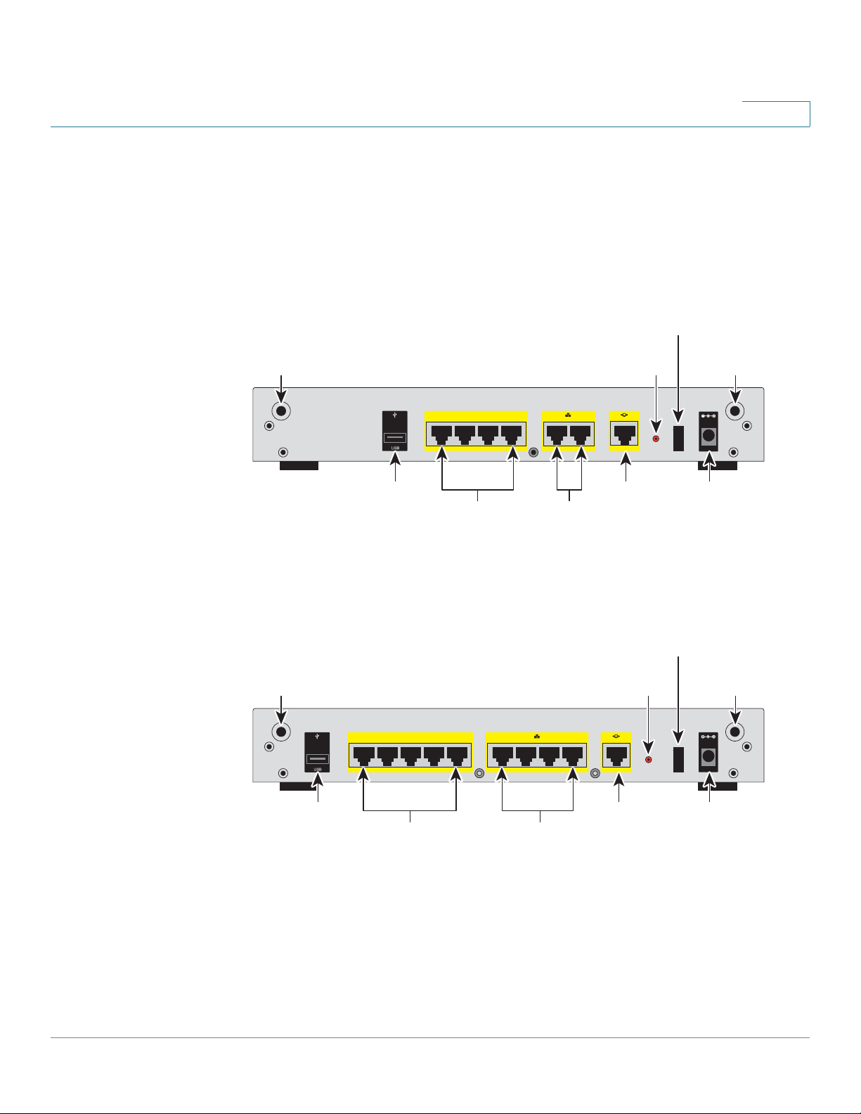
Back Panel
The back panel is where you connect the network devices. The ports on the panel
vary depending on the model.
ISA550 and ISA550W Back Panel
ISA570 and ISA570W Back Panel
Cisco ISA500 Series Integrated Security Appliance Administration Guide 17
Page 24

Getting Started
Installation
1
Back Panel Descriptions
Feature Description
ANT01/ANT02 Threaded connectors for the antennas (for ISA550W and
ISA570W only).
USB Port Connects the unit to a USB device. You can use a USB
device to backup and restore the configurations, or to
upgrade the firmware images.
Configurable
Ports
LAN Ports Connects PCs and other network appliances to the unit.
WAN Port Connects the unit to a DSL or a cable modem, or another
RESET Button To reboot the unit, push and release the RESET button. To
Power Switch Turns the unit on or off.
Power
Connector
NOTE The back panel of ISA550 and ISA570 does not include two threaded connectors
for the antennas.
Can be set to operate as WAN, LAN, or DMZ ports. The
ISA550 and ISA550W have 4 configurable ports. The
ISA570 and ISA570W have 5 configurable ports.
The ISA550 and ISA550W have 2 dedicated LAN ports.
The ISA570 and ISA570W have 4 dedicated LAN ports.
WAN connectivity device.
restore the factory default settings, push and hold the
RESET button for 3 seconds.
Connects the unit to power using the supplied power cord
and adapter.
Installation
This section describes how to install the security appliance. It includes the
following topics:
• Before You Begin, page 19
Cisco ISA500 Series Integrated Security Appliance Administration Guide 18
Page 25

Getting Started
Installation
1
• Installation Options, page 19
• Hardware Installation, page 22
Before You Begin
Before you begin the installation, make sure that you have the following
equipments and services:
• An active Internet account.
• Mounting kits and tools for installing the hardware. The kits packed with the
security appliance are used for desktop placement and rack mounting. The
kits include 4 rubber feet, 2 brackets, 2 silicon rubber spacers, 8 M3
screws, 4 M5 screws, and 4 washers.
NOTE The Wall-mounting kit is not included.
• RJ-45 Ethernet cables (Category 5 or higher) for connecting computers,
WAN and LAN interfaces, or other devices.
• A computer with Microsoft Internet Explorer 8.0, or Mozilla Firefox 3.6.x (or
later) for using the web-based Configuration Utility.
Installation Options
You can place your security appliance on a desktop, mount it on a wall, or mount it
in a rack. It includes the following topics:
• Placement Tips, page 19
• Wall Mounting, page 20
• Rack Mounting, page 21
Placement Tips
• Ambient Temperature: To prevent the security appliance from overheating,
do not operate it in an area that exceeds an ambient temperature of 104°F
(40°C).
• Air Flow: Be sure that there is adequate air flow around the device.
Cisco ISA500 Series Integrated Security Appliance Administration Guide 19
Page 26
Getting Started
1
2
4
3
196243
Installation
1
• Mechanical Loading: Be sure that the security appliance is level and stable
to avoid any hazardous conditions.
To place the security appliance on a desktop, install the supplied four rubber feet
on the bottom of the security appliance. Place the security appliance on a flat
surface.
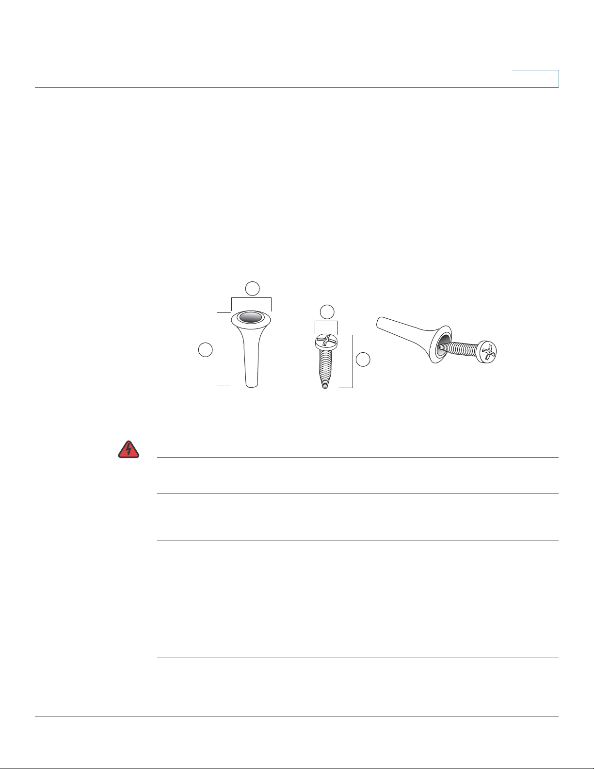
Wall Mounting
There is no wall-mounting kit included with your security appliance. We
recommend that you use the following screws to install your security appliance to
the wall or the ceiling:
1 8mm/0.32 in 2 25mm/0.98 in 3 6.5mm/0.26in 4 18.6mm/0.73in
WARNING Insecure mounting might damage the device or cause injury. Cisco is not
responsible for damages incurred by improper wall-mounting.
To mount the security appliance to the wall:
STEP 1 Determine where you want to mount the security appliance. Verify that the surface
is smooth, flat, dry, and sturdy.
STEP 2 Insert two 18.6 mm (0.73 inch) screws, with anchors, into the wall 234 mm apart
(9.21 inches). Leave 3 to 4 mm (about 1/8 inch) of the head exposed.
STEP 3 Place the security appliance wall-mount slots over the screws. Slide the security
appliance down until the screws fit snugly into the wall-mount slots.
Cisco ISA500 Series Integrated Security Appliance Administration Guide 20
Page 27
Getting Started
!
Installation
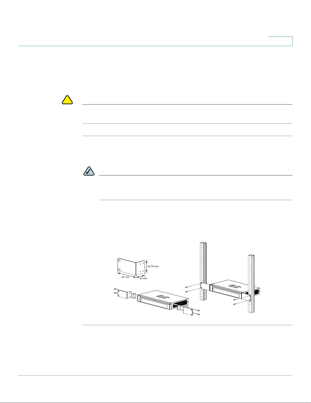
CAUTION Do not overload the power outlet or circuit when installing multiple devices in a
1
Rack Mounting
You can mount the security appliance in any standard size, 19-inch (about 48 cm)
wide rack. The security appliance requires 1 rack unit (RU) of space, which is 1.75
inches (44.45 mm) high.
rack.
STEP 1 Place one of the supplied silicon rubber spacers on the side of the security
appliance so that the four holes align to the screw holes. Place the rack mount
bracket next to the silicon rubber spacer and install the M3 screws.
NOTE If the M3 screws are not long enough to reattach the bracket with the silicon
rubber spacer, attach the bracket directly to the case without the silicon
rubber spacer.
STEP 2 Install the security appliance into a standard rack as shown below. Place the
washers on the brackets so that the holes align to the screw holes and then install
the M5 screws.
Step 1
Step 2
281985
Cisco ISA500 Series Integrated Security Appliance Administration Guide 21
Page 28
Getting Started
I
/
O
RESET
ANT02ANT01
1
6
7
8910
WAN
CONFIGURABLE
POWER
12VDC
2
3
4
5
LAN
Internet
Access
Device
Public
Web Server
Power
Network
Devices
Installation
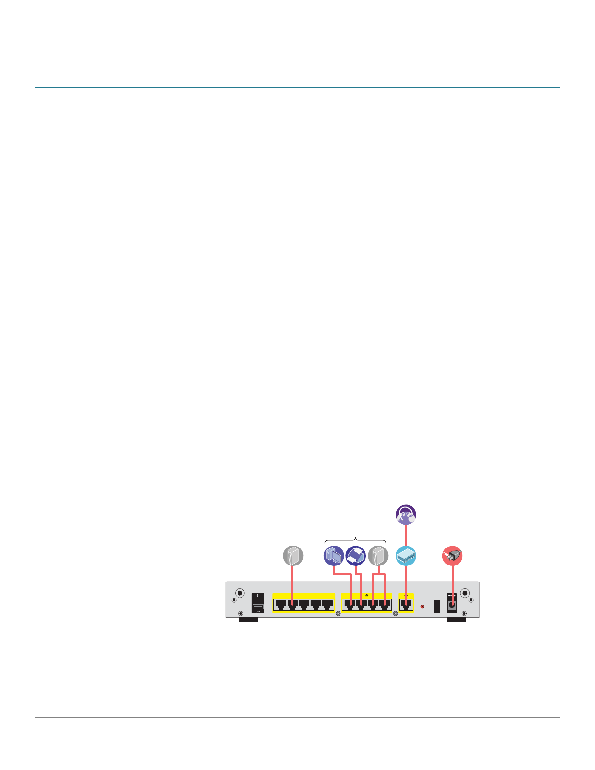
1
Hardware Installation
Follow these steps to connect the security appliance:
STEP 1 Connect the security appliance to power using the supplied power cord and
adapter. Make sure that the power switch is turned off.
STEP 2 If you are installing the ISA550W and ISA570W, screw each antenna onto a
threaded connector on the back panel. Orient each antenna to point upward.
STEP 3 For a DSL or cable modem, or other WAN connectivity devices, connect an
Ethernet network cable from the device to the WAN port on the back panel. Cisco
strongly recommends using Cat5E or better cable.
STEP 4 For network devices, connect an Ethernet network cable from the network device
to one of the dedicated LAN ports on the back panel.
STEP 5 For a UC 500 or a UC 300, connect an Ethernet network cable from the WAN port
of the UC 500 or a UC 300 to an available LAN port of the security appliance.
STEP 6 For a UC500 or a UC300, connect an Ethernet network cable from the WAN port of
the UC500 or UC300 to an available LAN port on the back panel of the security
appliance.
STEP 7 Power on the connected devices.
STEP 8 Power on the security appliance. The lights on the front panel for all connected
ports light up to show active connections.
A sample configuration is illustrated below.
Congratulations! The installation of the security appliance is complete.
Cisco ISA500 Series Integrated Security Appliance Administration Guide 22
Page 29

Getting Started
Getting Started with the Configuration Utility
Getting Started with the Configuration Utility
The Configuration Utility is a web based device manager that is used to provision
the security appliance. To use this utility, you must be able to connect to the
security appliance from your administration PC or laptop. You can access the
security appliance by using web browser such as Microsoft Internet Explorer 8.0,
or Mozilla Firefox 3.6.x (or later). It includes the following sections:
• Launching the Configuration Utility, page 23
• Navigating Through the Configuration Utility, page 24
• Using the Help System, page 25
• Using the Management Buttons, page 25
1
Launching the Configuration Utility
STEP 1 Connect your computer to an available LAN port on the back panel of the security
appliance.
STEP 2 Start a web browser. In the Address bar, enter the default IP address of the
security appliance: 192.168.1.1.
NOTE The above address is the factory default LAN address. If you change this
setting in the DEFAULT VLAN configuration, you will need to enter the new IP
address to connect to the Configuration Utility.
STEP 3 Enter the default user name and password in the login screen:
• Username: cisco
• Password: cisco
STEP 4 Click Login.
For the first login, you are forced to immediately change the default user name and
password of the default administrator account to prevent unauthorized access.
For more information, see Changing the User Name and Password of the
Default Administrator Account at Your First Login, page 27.
Cisco ISA500 Series Integrated Security Appliance Administration Guide 23
Page 30

Getting Started
1
2
Getting Started with the Configuration Utility
After you change them, the Startup Wizard launches. For more information about
how to use the Startup Wizard to configure your security appliance, see Using the
Startup Wizard, page 32.
Navigating Through the Configuration Utility
Use the left hand navigation pane and content pane to perform the tasks in the
Configuration Utility.
1
Number Components Description
1Left Hand
Navigation
2 Content Pane The content of the feature or subfeature appears in
Cisco ISA500 Series Integrated Security Appliance Administration Guide 24
Pane
The left hand navigation pane provides easy
navigation through the configurable features. The
main branches expand to provide the features.
Click on the main branch title to expand its
contents. Click on the right arrow of a feature to
open its subfeatures, or click on the down arrow of
a feature to contract its subfeatures. Click on the
title of a feature or subfeature to open it.
this area.
Page 31

Getting Started
About the Default Settings
1
Using the Help System
The Configuration Utility includes a detailed Help file for all configuration tasks. To
view the Help page, click the Help link in the top right corner of the screen.
Using the Management Buttons
Device Management buttons and icons provide an easy method of configuring
device information. In this guide, we use the texts by replacing the buttons or icons
to indicate what the buttons or icons are used for.
Icons Actions Icons Actions
Move Expand
Move Down Collapse
Move Up Edit or other specific actions
About the Default Settings
The security appliance is predefined with the settings that allow you to start using
the device with minimal changes needed. Depending the requirements of your
Internet Service Provider (ISP) and the needs of your business, you might need to
modify some of these settings. You can use the Configuration Utility to customize
all settings, as needed.
with relative description
Delete or Delete Selection
Settings of particular interest are described below. For a full list of all factory
default settings, see Appendix C, "Factory Default Settings."
Cisco ISA500 Series Integrated Security Appliance Administration Guide 25
Page 32

Getting Started
About the Default Settings
1
• IP Routing Mode: By default, only the IPv4 mode is enabled. To support the
IPv4 and IPv6 addressing, you need to enable the IPv4/IPv6 mode. To
change the IP routing mode, see Configuring IP Routing Mode, page 95.
• WAN Configuration: By default, the security appliance is configured to
obtain an IP address from your ISP by using Dynamic Host Configuration
Protocol (DHCP). Depending on the requirement of your ISP, you will need to
configure the network address mode for the primary WAN and the
secondary WAN if applicable. You can change other WAN settings as well.
See Configuring the WAN, page 101.
• LAN Configuration: By default, the LAN of the security appliance is
configured in the 192.168.1.0 subnet and the LAN IP address is 192.168.1.1.
The security appliance acts as a DHCP server to the hosts on the WLAN or
LAN network. It can automatically assign IP addresses and DNS server
addresses to the PCs and other devices on the LAN. For most deployment
scenarios, the default DHCP and TCP/IP settings should be satisfactory.
However, you can change the subnet address or the default IP address. You
can assign static IP addresses to connected devices rather than allowing the
security appliance to act as a DHCP server. See Configuring the VLAN,
page 118.
• VLAN Configuration: The security appliance predefines a native VLAN
(DEFAULT) and a guest VLAN (GUEST). You can customize new VLANs for
your specific business needs. See Configuring the VLAN, page 118.
• Configurable Ports: By default, all configurable ports are set to act as LAN
ports. Alternatively, you can configure the configurable port for use as a DMZ
port or a secondary WAN port. See Configuring the WAN, page 101 or
Configuring the DMZ, page 123.
• Wireless Network (for ISA550W and ISA570W only): The ISA550W or
ISA570W is configured with four SSIDs. All SSIDs are disabled by default.
For security purposes, we strongly recommend that you configure the SSIDs
with the appropriate security settings. See Wireless Configuration for
ISA550W and ISA570W, page 157.
• Administrative Access: You can access the Configuration Utility by using a
web browser and entering the default LAN IP address of 192.168.1.1. You
can log into by entering the username and password of the default
administrator account. You are forced to change the default username and
password after the first login. See Changing the User Name and Password
of the Default Administrator Account at Your First Login, page 27. You
also may want to change the user login settings for authentication. See
Configuring the User Authentication Settings, page 277.
Cisco ISA500 Series Integrated Security Appliance Administration Guide 26
Page 33

Getting Started
Performing Common Configuration Tasks
• Security Services: By default, the UTM security services such as Intrusion
Prevention Service (IPS), Web URL Filter, Web Reputation Filter, Anti-Virus,
and Email Reputation Filter are disabled. For more information about how to
configure the security services, see Security Services, page 210.
• Firewall: By default, the firewall prevents inbound traffic and allows all
outbound traffic. If you want to allow some inbound traffic or prevent some
outbound traffic, you must customize firewall access rules. The security
appliance supports up to 100 custom access rules. See Configuring the
Firewall Access Rules to Control Inbound and Outbound Traffic,
page 178.
• VPN: By default, the VPN feature is disabled. The security appliance can
function as a Cisco IPSec VPN server or a Cisco VPN hardware client, or as
a SSL VPN gateway so that remote users can securely access the corporate
network resources over the VPN tunnels. You can also establish a secure
IPSec VPN tunnel between two sites that are physically separated by using
the Site-to-Site VPN feature. For more information about how to configure the
VPN features, see VPN, page 232.
1
Performing Common Configuration Tasks
We strongly recommend that you complete the following common tasks before
you begin configuring your security appliance. It includes the following sections:
• Changing the User Name and Password of the Default Administrator
Account at Your First Login, page 27
• Saving Your Configuration, page 28
• Upgrading the Firmware if needed, page 29
• Resetting the Device, page 30
Changing the User Name and Password of the Default Administrator Account at Your First Login
The default administrator account is an administrative account that has fully
privilege to set the configurations and read the system status. It does not belong to
any user group. To prevent unauthorized access, you are forced to immediately
change the default user name and password at its first login.
Cisco ISA500 Series Integrated Security Appliance Administration Guide 27
Page 34

Getting Started
Performing Common Configuration Tasks
STEP 1 After the first login, a prompt window opens.
STEP 2 Enter the following information:
• User Name: Enter a new user name that contains the letters, numbers, or
underline for the default administrator account.
• New Password: Enter a new password for the default administrator account.
Passwords are case-sensitive.
NOTE Restrictions for password: The password should contain at least
1
three types of these character classes: lower case letters, upper case
letters, numbers, and special characters. Do not repeat any character
more than three times consecutively. Do not set the password as the
user name or the reversed user name. The password cannot be set as
“cisco”, “ocsic”, or any variant obtained by changing the capitalization
of letters.
• Confirm Password: Enter the new password again for confirmation.
STEP 3 Click Save to apply your settings.
Saving Your Configuration
At any point during the configuration process, you can save your configurations.
Later, if you make changes that you want to abandon, you can easily revert to the
saved configurations.
STEP 1 Click Device Management -> Firmware and Configuration -> Configuration.
The Configuration window opens.
STEP 2 To save the current settings on your local PC, perform the following steps:
a. In Backup/Restore Settings area, click Backup after the Save A Copy of
Current Settings option.
b. The Encryption window opens. You can optionally encrypt the configurations
for security purposes, check the Encrypt box and enter the password in the
Key field, and then click OK.
Cisco ISA500 Series Integrated Security Appliance Administration Guide 28
Page 35

Getting Started
!
Performing Common Configuration Tasks
c. Locate where to save the configuration file, and then click Save.
STEP 3 To save the current settings on a USB device, perform the following steps:
a. Insert a USB device into the USB interface on the back panel of your security
appliance. The USB device is automatically mounted once you insert it.
b. In the USB -> Mount/Unmount area, check the mounting status of the USB
device. Make sure that the USB Driver Status shows as “UP” when you use the
USB device to manage the configurations.
c. In the USB -> Backup/Restore Settings area, click Backup after the Save A
Copy of Current Settings option.
d. The Encryption window opens. You can optionally encrypt the configurations
for security purposes, check the Encrypt box and then enter the password in
the Key field, and then click OK. Your current settings are saved as a
configuration file on the root folder of the USB device.
1
Upgrading the Firmware if needed
Before you do any other tasks, ensure that you are using the latest firmware
version. You can upgrade from a firmware file stored on your computer or a
mounted USB device.
CAUTION During a firmware upgrade, do NOT try to go online, turn off the device, shut down
the PC, remove the cable, or interrupt the process in anyway until the operation is
complete. This process should take several minutes or so including the reboot
process. Interrupting the upgrade process at specific points when the flash is
being written to can corrupt the flash memory and render the security appliance
unusable.
STEP 1 Click Device Management -> Firmware and Configuration -> Firmware.
The Firmware window opens.
Cisco ISA500 Series Integrated Security Appliance Administration Guide 29
Page 36

Getting Started
!
Performing Common Configuration Tasks
STEP 2 To manually upgrade the firmware from your local PC, perform the following steps:
a. In the Network -> Firmware Upgrade area, click Browse to locate and select
the firmware image from your local PC.
b. To upgrade the firmware and keep using the current settings, click Upgrade.
c. To upgrade the firmware and revert to the factory default settings, click
Upgrade & Factory Reset. When the operation is complete, the security
appliance automatically reboots with the factory default settings.
STEP 3 To upgrade the firmware through a USB device, perform the following steps:
a. Insert the USB device with the firmware images into the USB interface on the
back panel of your security appliance. The USB device is automatically
mounted after you inserted it.
b. In the USB -> Mount/Unmount area, check the mounting status of the USB
device. Make sure that the USB Driver Status shows as “UP” when you use the
USB device to manage the firmware.
1
c. In the USB -> Backup/Restore Settings area, all firmware images located on
the USB device appears in the list.
• To upgrade the firmware and keep using the current settings, select the
latest firmware image from the list and then click Upgrade.
• To upgrade the firmware and revert to the factory default settings, select the
latest firmware image from the list and then click Upgrade & Factory Reset.
When the operation is complete, the security appliance automatically
reboots with the factory default settings.
Resetting the Device
To revert your security appliance to the factory default settings, you can press and
hold the RESET button on the back panel for minimum of 3 seconds, or perform the
following procedures.
CAUTION The Revert To Factory Default Settings operation will wipe out the current
configurations used on your security appliance (including the imported
certificates). We recommmend that you save the current settings before reverting
to the factory default settings.
Cisco ISA500 Series Integrated Security Appliance Administration Guide 30
Page 37

Getting Started
Performing Common Configuration Tasks
STEP 1 Click Device Management -> Firmware and Configuration -> Configuration.
The Configuration window opens.
STEP 2 In the Backup/Restore Settings -> Revert To Factory Default Settings area,
click Default.
The security appliance will reboot with the factory default settings.
1
Cisco ISA500 Series Integrated Security Appliance Administration Guide 31
Page 38

Wizards
2
This chapter describes how to use the wizards to configure your security
appliance.
• Using the Startup Wizard, page 32
• Using the Wireless Wizard to Configure the Wireless Settings for
ISA550W and ISA570W, page 40
• Using the DMZ Wizard to Configure the DMZ Settings, page 46
• Using the Dual WAN Wizard to Configure the WAN Redundancy
Settings, page 51
• Using the Site-to-Site Wizard to Establish the Site-to-Site VPN Tunnels,
page 53
• Using the Remote Access Wizard to Establish the IPSec VPN Tunnels or
SSL VPN Tunnels for Remote Access, page 58
To access the Wizards pages, click Wizards in the left hand navigation pane.
Using the Startup Wizard
The Startup Wizard helps you configure the remote management, port, WAN, LAN,
DMZ, and WLAN (for ISA550W and ISA570W only) settings. The first time you log
into your security appliance, the Startup Wizard automatically launches.
STEP 1 Click Wizard -> Startup Wizard.
The Getting Started window opens. A prompt warning message is displayed as
below.
Cisco ISA500 Series Integrated Security Appliance Administrator Guide 32
Page 39

Wizards
!
Using the Startup Wizard
CAUTION When the Startup Wizard is complete, the previous settings relevant to the
STEP 2 Click Begin.
2
changed WAN, DDNS, LAN, DMZ, and WLAN are cleaned up, and relevant services
are reinitialized.
For the first login, you can ignore this warning message and follow the on-screen
prompts to complete the initial configuration. If you have already configured the
security appliance, make sure that you have read the warning message before you
use the Startup Wizard to configure your security appliance. Click OK to close the
warning message window.
The Remote Management window opens. The security appliance allows remote
management securely by using HTTPS and HTTP. For example, https://
xxx.xxx.xxx.xxx:8080.
Enter the following information:
• Remote Management: Click On to enable remote management by using
HTTPS, or click Off to disable it. We recommend that you use HTTPS for
secure purposes.
• HTTPS Listen Port Number: If you enable remote management by using
HTTPS, enter the port number to be listened on. By default, the listened port
for HTTPS is 8080.
• HTTP Enable: Click On box to enable remote management by using HTTP,
or click Off to disable it.
• HTTP Listen Port Number: If you enable remote management by using
HTTP, enter the port number to be listened on. By default, the listened port
for HTTP is 80.
• Access Type: Choose the level of permission for remote management:
- Allow access from any IP address: Any IP address from a remote WAN
network can access the Configuration Utility.
- Restrict a specific IP address: Only the specified remote host can
access the Configuration Utility. Enter the IP address of the remote host
in the IP Address field.
Cisco ISA500 Series Integrated Security Appliance Administrator Guide 33
Page 40

Wizards
Using the Startup Wizard
STEP 3 After you are finished, click Next.
2
- Restrict access to a range of IP addresses: Only the hosts in the
specified remote network can access the Configuration Utility. Enter the
starting IP address in the From field and the ending IP address in the To
field.
• Remote SNMP: Click On to enable SNMP for the remote connection, or click
Off to disable SNMP. Enabling SNMP allows remote users to use the SNMP
protocol to access the Configuration Utility.
The Port Configuration window opens. From this page you can specify the port
configuration. The Startup Wizard predefines four port configuration solutions. You
can also modify the port types for the configurable ports when you create a
secondary WAN or configure the DMZs.
If you are using the ISA570 or ISA570W, choose one of the following options:
• 1 WAN, 9 LAN Switch: This is the default setting. The security appliance is
set to one WAN port (WAN1) and nine LAN ports.
• 1 WAN, 1 DMZ, and 8 LAN Switch: The security appliance is set to one
WAN port (WAN1), one DMZ port, and eight LAN ports. The configurable port
GE10 is set to a DMZ port.
• 1 WAN, 1 WAN Backup, and 8 LAN Switch: The security appliance is set to
two WA N po rts (WA N1 is th e pr imar y WAN and WAN2 i s the se con dar y
WAN) and eight LAN ports. The configurable port GE10 is set to a secondary
WAN p or t.
• 1 WAN, 1 WAN Backup, 1 DMZ, and 7 LAN Switch: The security appliance
is set to two WAN ports (WAN1 is the primary WAN and WAN2 is the
secondary WAN), one DMZ port, and seven LAN ports. The configurable
port GE10 is set to a secondary WAN port and the configurable port GE9 is
set to a DMZ port.
If you are using the ISA550 or ISA550W, choose one of the following options:
• 1 WAN, 6 LAN Switch: This is the default setting. The security appliance is
set to one WAN port (WAN1) and six LAN ports.
• 1 WAN, 1 DMZ, and 5 LAN Switch: The security appliance is set to one
WAN port (WAN1), one DMZ port, and five LAN ports. The configurable port
GE7 is set to a DMZ port.
Cisco ISA500 Series Integrated Security Appliance Administrator Guide 34
Page 41

Wizards
Using the Startup Wizard
2
• 1 WAN, 1 WAN Backup, and 5 LAN Switch: The security appliance is set to
two WA N po rts (WA N1 is th e pr imar y WAN and WAN2 i s the se con dar y
WAN) and five LAN ports. The configurable port GE7 is set to a secondary
WAN p or t.
• 1 WAN, 1 WAN Backup, 1 DMZ, and 4 LAN Switch: The security appliance
is set to two WAN ports (WAN1 is the primary WAN and WAN2 is the
secondary WAN), one DMZ port, and four LAN ports. The configurable port
GE7 is set to a secondary WAN port and the configurable port GE6 is set to
a DMZ port.
NOTE If you have two ISP links, we recommend that you set a backup WAN
so that you can provide backup connectivity or load balancing. If you
need to host public services, we recommend that you set a DMZ port.
NOTE The configurable ports can be set as the WAN, LAN, and DMZ ports.
Up to two WAN ports and four DMZ ports can be configured on the
security appliance. To configure multiple DMZ ports, go to the
Networking -> DMZ page. For more information, see Configuring the
DMZ, page 123.
STEP 4 After you are finished, click Next.
The Primary WAN Connection window opens. From this page you can configure
the primary WAN port.
Choose the network addressing mode from the IP Address Assignment dropdown list and complete the corresponding fields for the primary WAN port
depending on the requirements of your ISP. The security appliance supports
DHCPC, Static IP, PPPoE, PPTP, and L2TP. For complete details, see Configuring
the Network Addressing Mode, page 106.
NOTE If only one single WAN port is c onfigured on your security appliance, skip the
next two steps and proceed to the step 7.
STEP 5 After you are finished, click Next.
The Secondary WAN Connection window opens. From this page you can
configure the secondary WAN port.
Cisco ISA500 Series Integrated Security Appliance Administrator Guide 35
Page 42

Wizards
Using the Startup Wizard
STEP 6 After you are finished, click Next.
2
Choose the network addressing mode from the IP Address Assignment dropdown list and complete the corresponding fields for the secondary WAN port
depending on the requirements of your ISP. For complete details, see Configuring
the Network Addressing Mode, page 106.
The WAN Redundancy window opens. From this page you can determine how the
two ISP links are used.
• Use the Loab Balancing mode if you want to use both ISP links
simultaneously. The two links will carry data for the protocols that are bound
to them. Enter the following information:
- Equal Load Balancing (Round Robin): Re-orders the WAN interfaces for
Round Robin selection. The order is as follows: WAN1 and WAN2. The
Round Robin will then repeat back to WAN1 and continue the order.
- Weighted Load Balancing: Distributes the bandwidth to two WAN ports
by the weighted percange or by the weighted link bandwidth. If you
choose this mode, then choose one of the following options and finish the
setting:
Weighted By percentage: Allows you to set the percentage for each
WAN, such as 80% percentage bandwidth for WAN1 and lest 20%
percentage bandwidth for WAN2.
Weighted By Link Bandwidth: Allows you to set the rate limiting for each
WAN, such as 10 Mbps for WAN1 and 5 Mbps for WAN2.
• Use the Failover mode if you want to use one ISP link as a backup. If a failure
is detected on the primary link, then the security appliance directs all
Internet traffic to the backup link. When the primary link regains connectivity,
all Internet traffic is directed to the primary link, and the backup link becomes
idle. Enter the following information:
- Auto Failover to: Choose either WAN1 or WAN2 as the primary link. By
default, WAN1 is set as the primary link and WAN2 is set as the backup
link. You can also set WAN2 as the primary link.
- Preempt Delay Timer: Enter the time in seconds that the system will
preempt the primary link from the backup link when the primary link is up
again. The default is 5 seconds.
STEP 7 After you are finished, click Next.
The LAN Configuration window opens. From this page you can configure the
default LAN settings.
Cisco ISA500 Series Integrated Security Appliance Administrator Guide 36
Page 43

Wizards
Using the Startup Wizard
2
• IP: Enter the IP address of the default LAN.
• Netmask: Enter the IP address of the netmask.
• DHCP Server: Choose one of the following DHCP modes:
- Disable: Choose this option if the computers on the VLAN are configured
with static IP addresses or are configured to use another DHCP server.
- DHCP Server: Allows the security appliance to act as a DHCP server and
assigns IP addresses to all devices that are connected to the DEFAULT
VLAN. Any new DHCP client joining the DEFAULT VLAN is assigned an IP
address of the DHCP pool.
- DHCP Relay: Allows the security appliance to use a DHCP Relay. If you
choose DHCP Relay, enter the IP address of the remote DHCP server in
the Relay IP field.
If you choose DHCP Server as the DHCP mode, enter the following information:
• Start IP: Enter the starting IP address of the DHCP pool.
• End IP: Enter the ending IP address of the DHCP pool.
NOTE The starting and ending IP addresses should be in the same range as
the LAN’s subnet address.
• Lease Time: Enter the maximum connection time that a dynamic IP address
is “leased” to a network user. When the time elapses, the user is
automatically renewed the dynamic IP address.
• DNS 1: Enter the IP address of the primary DNS server.
• DNS 2: Optionally, enter the IP address of the secondary DNS server.
• WINS 1: Enter the IP address for the primary WINS server.
• WINS 2: Optionally, enter the IP address of the secondary WINS server.
• Domain Name: Optionally, enter the domain name for the default LAN.
• Default Gateway: Enter the IP address of default gateway.
STEP 8 After you are finished, click Next.
If you have no DMZ port, skip the next two steps and proceed to the step 10.
Cisco ISA500 Series Integrated Security Appliance Administrator Guide 37
Page 44

Wizards
Using the Startup Wizard
2
If you have a DMZ port, the DMZ Configuration window opens. To host public
services, you need to configure a DMZ network in this page and specify the
relevant DMZ services from the next DMZ Service page.
• IP: Enter the subnet IP address of the DMZ.
• Netmask: Enter the subnet mask of the DMZ.
• DHCP Service: Choose one of the following options:
- Disable: Choose this option if the computers on the DMZ are configured
with static IP addresses or are configured to use another DHCP server.
- DHCP Server: Allows the security appliance to act as a DHCP server and
assigns IP addresses to all devices that are connected to the DMZ. Any
new DHCP client joining the DMZ is assigned an IP address of the DHCP
pool.
- DHCP Relay: Allows the security appliance to use a DHCP Relay. If you
choose DHCP Relay, enter the IP address of the remote DHCP server in
the Relay IP field.
If you choose DHCP Server as the DHCP mode, enter the following information:
• Start IP: Enter the starting IP address of the DHCP pool.
• End IP: Enter the ending IP address of the DHCP pool.
NOTE The starting and ending IP addresses should be in the same range as
the DMZ’s subnet address.
• Lease Time: Enter the maximum connection time that a dynamic IP address
is “leased” to a network user. When the time elapses, the user is
automatically renewed the dynamic IP address.
• DNS 1: Enter the IP address of the primary DNS server.
• DNS 2: Optionally, enter the IP address of the secondary DNS server.
• WINS 1: Enter the IP address for the primary WINS server.
• WINS 2: Optionally, enter the IP address of the secondary WINS server.
• Domain Name: Optionally, enter the domain name for the DMZ.
• Default Gateway: Enter the IP address of default gateway.
Cisco ISA500 Series Integrated Security Appliance Administrator Guide 38
Page 45

Wizards
Using the Startup Wizard
STEP 9 After you are finished, click Next.
STEP 10 After you are finished, click Next.
2
The DMZ Service window opens. From this page you can configure the DMZ
services. For complete details, see Configuring the DMZ Services, page 49.
NOTE After you configure the DMZ services, the firewall access rules will
automatically generated by the security appliance to allow the access to the
services on your DMZ.
The Wireless Radio Setting window opens. From this page you can configure the
wireless radio settings.
NOTE The wireless configurations such as wireless radio settings and Intranet
WLAN access (see next step) are only available for the ISA550W and
ISA570W. If your security appliance is not a wireless device, proceed to the
step 12.
• Wireless Network Mode: Choose the 802.11 modulation technique. The
ISA550W and ISA550W supports the following radio modes:
- 802.11b only: Choose this mode if all devices in the wireless network
use 802.11b. Only 802.11b clients can connect to the access point.
- 802.11g only: Choose this mode if all devices in the wireless network
use 802.11g. Only 802.11g clients can connect to the access point.
- 802.11b/g mixed: Choose this mode if some devices in the wireless
network use 802.11b and others use 802.11g. Both 802.11b and 802.11g
clients can connect to the access point.
- 802.11n only: Choose this mode if all devices in the wireless network
can support 802.11n. Only 802.11n clients operating in the 2.4 GHz
frequency can connect to the access point.
- 802.11g/n mixed: Choose this mode to allow 802.11g and 802.11n
clients operating in the 2.4 GHz frequency to connect to the access point.
- 802.11b/g/n mixed: Choose this mode to allow 802.11b, 802.11g, and
802.11n clients operating in the 2.4 GHz frequency to connect to the
access point.
Cisco ISA500 Series Integrated Security Appliance Administrator Guide 39
Page 46

Wizards
Using the Wireless Wizard to Configure the Wireless Settings for ISA550W and ISA570W
• Wireless Channel: Choose a channel or choose Auto to let the system
determine the best channel to use based on the environmental noise levels
for the available channels.
STEP 11 After you are finished, click Next.
The Wireless Connectivity Type - Intranet WLAN Access window opens. From this
page you can configure the wireless connectivity settings for the SSID1.
NOTE The ISA550W and ISA570W support four SSIDs. To configure the wireless
connectivity settings for other SSIDs, go to the Wireless -> Basic Settings
page or use the Wireless wizard. For more information, see Configuring the
Access Points, page 151 or Using the Wireless Wizard to Configure the
Wireless Settings for ISA550W and ISA570W, page 40.
2
• SSID Name: The SSID name.
• Security Mode: Choose the encryption algorithm for data encryption for this
SSID. Depending on the selected security mode, configure the
corresponding settings. See Configuring the Security Mode, page 162.
• VLAN Name: Choose the VLAN to which this SSID is mapped. All traffic from
the wireless clients that are connected to this SSID will be directed to the
selected VLAN.
STEP 12 After you are finished, click Next.
The Summary window opens. The Summary page displays the summary
information for all configurations you made.
STEP 13 Click Submit to save the settings.
Using the Wireless Wizard to Configure the Wireless Settings
for ISA550W and ISA570W
Use the Wireless Wizard to configure the wireless radio and Intranet connectivity
settings for the ISA550W and ISA570W. It includes the following sections:
• Using the Wireless Wizard to Configure the Wireless Settings, page 41
Cisco ISA500 Series Integrated Security Appliance Administrator Guide 40
Page 47

Wizards
Using the Wireless Wizard to Configure the Wireless Settings for ISA550W and ISA570W
• Configuring the SSID for Intranet WLAN Access, page 43
• Configuring the SSID for Guest WLAN Access, page 44
• Configuring the SSID for Guest WLAN Access (Captive Portal), page 45
Using the Wireless Wizard to Configure the Wireless Settings
STEP 1 Click Wizards -> Wireless Wizard.
The Getting Started window opens.
STEP 2 Click Begin.
The Wireless Radio Setting window opens. Enter the following information:
• Wireless Network Mode: Specify the Physical Layer (PHY) standard that
the wireless radio uses.
2
- 802.11b only: Choose this mode if all devices in the wireless network
use 802.11b. Only 802.11b clients can connect to the access point.
- 802.11g only: Choose this mode if all devices in the wireless network
use 802.11g. Only 802.11g clients can connect to the access point.
- 802.11b/g mixed: Choose this mode if some devices in the wireless
network use 802.11b and others use 802.11g. Both 802.11b and 802.11g
clients can connect to the access point.
- 802.11n only: Choose this mode if all devices in the wireless network
can support 802.11n. Only 802.11n clients operating in the 2.4 GHz
frequency can connect to the access point.
- 802.11g/n mixed: Choose this mode to allow 802.11g and 802.11n
clients operating in the 2.4 GHz frequency to connect to the access point.
- 802.11b/g/n mixed: Choose this mode to allow 802.11b, 802.11g, and
802.11n clients operating in the 2.4 GHz frequency to connect to the
access point.
• Wireless Channel: Choose a channel or choose Auto to let the system
determine the best channel to use based on the environmental noise levels
for the available channels.
STEP 3 After you are finished, click Next.
The Choose SSIDs window opens. From this page you can enable the SSIDs and
choose the wireless connectivity type for each active SSID.
Cisco ISA500 Series Integrated Security Appliance Administrator Guide 41
Page 48

Wizards
Using the Wireless Wizard to Configure the Wireless Settings for ISA550W and ISA570W
• Enable: Check this box to enable the SSID.
• Mode: Choose the wireless connectivity type for each enabled SSID.
- Intranet WLAN Access: Allows wireless users to access the corporate
network via the wireless network. The WLAN is mapped to the DEFAULT
VLAN.
- Guest WLAN Access: Only allows guest users to access the corporate
network via the wireless network. The WLAN is mapped to the GUEST
VLAN.
- Guest WLAN Access (Captive Portal): Only allows guest users who
authenticated successfully to access the corporate network via the
wireless network. The wireless users will be directed to a specific web
authentication login page to authenticate, and then be directed to a
specified web portal after login successfully before they can access the
Internet.
2
NOTE Only one SSID can be set for Guest WLAN access and Captive Portal
WLAN access.
STEP 4 Specify the wireless connectivity settings for all enabled SSIDs.
Depending on the wireless connectivity type that you selected for the SSID, you
need to complete the relevant settings for each enabled SSID.
For complete details to configure the Intranet WLAN access, see Configuring the
SSID for Intranet WLAN Access, page 43.
For complete details to configure the Guest WLAN access, see Configuring the
SSID for Guest WLAN Access, page 44.
For complete details to configure the Captive Portal WLAN access, see
Configuring the SSID for Guest WLAN Access (Captive Portal), page 45.
STEP 5 After you are finished, click Next.
The Summary window opens. The Summary page displays the summary
information for all configurations you made for the SSIDs.
STEP 6 Click Submit to save your settings and exit the Wireless Wizard.
Cisco ISA500 Series Integrated Security Appliance Administrator Guide 42
Page 49

Wizards
Using the Wireless Wizard to Configure the Wireless Settings for ISA550W and ISA570W
Configuring the SSID for Intranet WLAN Access
This section describes how to configure the connectivity settings for Intranet
WLAN access.
STEP 1 After you enable the SSIDs and specify the wireless connectivity type for each
SSID, click Next.
If SSID1 is enabled and is set to Intranet WLAN Access, the SSID1 window opens.
STEP 2 Enter the following information:
• SSID: Enter the SSID name.
• Broadcast SSID: Check the box to broadcast the SSID in its beacon frames.
All wireless devices within range are able to see the SSID when they scan
for available networks. Uncheck the box to prevent auto-detection of the
SSID. In this case, users must know the SSID to set up a wireless connection
to this SSID.
2
• PC Visibility: Check the box so that the wireless clients on the same SSID
will be able to see eachother.
STEP 3 In the Security Settings area, specify the wireless security settings.
• Security Mode: Choose the security mode and configure the
correspoinding information. For security purposes, Cisco strongly
recommends WPA2 for wireless security. For example, if you choose WPA2Personal, enter the following information:
- Encryption: WPA2-Personal always uses AES for data encryption.
- Shared Secret: The Pre-shared Key (PSK ) is the shared secret key for
WPA. Enter a string of at least 8 characters to a maximum of 63
characters.
- Key Renewal Timeout: Enter a value to set the interval at which the key
is refreshed for clients associated to this SSID. A value of 0 indicates that
the key is not refreshed. The default is 3600 seconds.
NOTE For complete details for other security modes, see Configuring the
Security Mode, page 162.
STEP 4 In the Advanced Settings area, enter the following information:
Cisco ISA500 Series Integrated Security Appliance Administrator Guide 43
Page 50

Wizards
Using the Wireless Wizard to Configure the Wireless Settings for ISA550W and ISA570W
• VLAN Mapping: Choose the VLAN to which the SSID is mapped. All traffic
from the wireless clients that are connected to this SSID will be directed to
the selected VLAN. For Intranet VLAN access, you should choose a VLAN
that is mapped to a trust zone.
• User Limit: Specify the maximum number of users that can simultaneously
connect to this SSID.
Configuring the SSID for Guest WLAN Access
This section describes how to configure the connectivity settings for Guest WLAN
access.
STEP 1 After you are finished the SSID1 configuration, click Next.
2
If SSID2 is enabled and is set to Guest WLAN Access, the SSID2 window opens.
STEP 2 Enter the following information:
• SSID: Enter the SSID name.
• Broadcast SSID: Check the box to broadcast the SSID in its beacon frames.
All wireless devices within range are able to see the SSID when they scan
for available networks. Uncheck the box to prevent auto-detection of the
SSID. In this case, users must know the SSID to set up a wireless connection
to this SSID.
• PC Visibility: Check the box so that the wireless clients on the same SSID
are able to see eachother.
STEP 3 In the Security Settings area, specify the wireless security settings.
• Security Mode: Choose the security mode and configure the
correspoinding information. For the complete details for how to configure the
security modes, see Configuring the Security Mode, page 162.
STEP 4 In the Advanced Settings area, enter the following information:
• VLAN Mapping: Choose the VLAN to which the SSID is mapped. All traffic
from the wireless clients that are connected to this SSID will be directed to
the selected VLAN. For Guest VLAN access, you should choose a VLAN that
is mapped to a guest zone.
Cisco ISA500 Series Integrated Security Appliance Administrator Guide 44
Page 51

Wizards
Using the Wireless Wizard to Configure the Wireless Settings for ISA550W and ISA570W
• User Limit: Specify the maximum number of users that can simultaneously
connect to this SSID.
Configuring the SSID for Guest WLAN Access (Captive Portal)
This section describes how to configure the connectivity settings for Captive
Portal WLAN access.
STEP 1 After you are finished the SSID2 configuration, click Next.
If SSID3 is enabled and is set to Guest WLAN Access (Captive Portal), the SSID3
window opens.
STEP 2 Enter the following information:
2
• SSID: Enter the SSID name.
• Broadcast SSID: Check the box to broadcast the SSID in its beacon frames.
All wireless devices within range are able to see the SSID when they scan
for available networks. Uncheck the box to prevent auto-detection of the
SSID. In this case, users must know the SSID to set up a wireless connection
to this SSID.
• PC Visibility: Check the box so that the wireless clients on the same SSID
are able to see eachother.
STEP 3 In the Security Settings area, specify the wireless security settings.
• Security Mode: Choose the security mode and configure the
correspoinding information. For the complete details for how to configure the
security modes, see Configuring the Security Mode, page 162.
STEP 4 In the Captive Portal WLAN Access -> Autentication area, enter the following
information:
• Autentication Method: The authentication method that is used to
authenticate the wireless users. This setting is derived from the user login
settings. Go to the Users -> Settings page to set the authentication method.
For more information, see Configuring the User Authentication Settings,
page 277.
STEP 5 In the Captive Portal WLAN Access -> Captive Portal Authentication Type area,
specify the web authentication type and configure the relevant settings:
• Web Authentication Type: Choose one of the following methods:
Cisco ISA500 Series Integrated Security Appliance Administrator Guide 45
Page 52

Wizards
Using the DMZ Wizard to Configure the DMZ Settings
- Internal: Allows you to use the default web authentication login page to
authenticate the wireless users. If you choose this option, enter the URL
of the portal in the Redirect URL After Login field and specify the
monitored HTTP port list. If you do not specify the portal, the wireless
user can access the original web site directly.
- External Web Server: Allows you to use a customized web
authentication login page on an external web server to authenticate the
wireless users. If you choose this option, enter the IP address of the
external web server in the Authentication Web Server field and the key
in the Authentiation Web Key field. The authentication web key is used
to protect the user name and password that the external web server
sends to your security appliance for authentication.
For example, if you select Internal for authentication and the web portal
is set to www.ABcompanyC.com, when a wireless user tries to access
the website www.google.com, the default web authentication login page
opens. The user needs to enter the user name and password, and then
click Submit. After login, the user is directed to the
www.ABcompanyC.com and can then access the www.google.com.
2
STEP 6 In the Advanced Settings area, enter the following information:
• VLAN Mapping: Choose the VLAN to which the SSID is mapped. All traffic
from the wireless clients that are connected to this SSID will be directed to
the selected VLAN.
• User Limit: Specify the maximum number of users that can simultaneously
connect to this SSID.
Using the DMZ Wizard to Configure the DMZ Settings
Use the DMZ Wizard to configure the DMZ and DMZ services if you need to host
public services. It includes the following sections:
• Using the DMZ Wizard to Configure the DMZ Settings, page 47
• Configuring the DMZ, page 48
• Configuring the DMZ Services, page 49
Cisco ISA500 Series Integrated Security Appliance Administrator Guide 46
Page 53

Wizards
Using the DMZ Wizard to Configure the DMZ Settings
Using the DMZ Wizard to Configure the DMZ Settings
STEP 1 Click Wizards -> DMZ Wizard.
The Getting Started window opens.
STEP 2 Click Begin.
The DDNS Setup window opens. From this page you can optionlly configure the
DDNS for the remote management of the DMZ network. Enter the following
information:
• Service: Choose either DynDNS or No-IP service.
• Active on Startup: Click On to activate the DDNS setting when the security
appliance starts up.
• User Name: Enter the user name of the account that you registered in the
DDNS provider.
2
• Password: Enter the password of the account that you registered in the
DDNS provider.
• Host & Domain Name: Specify the complete host name and domain name
for the DDNS service.
STEP 3 After you are finised, click Next.
The DMZ Configure window opens. From this page you can the DMZ network. For
complete details, see Configuring the DMZ, page 48.
STEP 4 After you are finished, click Next.
The DMZ Service window opens. From this page you can configure the DMZ
services. For complete details, see Configuring the DMZ Services, page 49.
NOTE After you configure the DMZ services, the firewall access rules will
automatically generated by the security appliance to allow the access to the
services on your DMZ.
STEP 5 After you are finished, click Next.
The Summary window opens. The Summary window displays the summary
information for all configurations you made.
Cisco ISA500 Series Integrated Security Appliance Administrator Guide 47
Page 54

Wizards
Using the DMZ Wizard to Configure the DMZ Settings
STEP 6 Click Submit to save your settings and exit the DMZ Wizard.
Configuring the DMZ
In the DMZ Configure window, follow these procedures to create a DMZ network.
STEP 1 Click Add to create a DMZ network.
Other Options: To edit an entry, click Edit. To delete an entry, click Delete.
The DMZ - Add/Edit window opens.
STEP 2 In the Basic Setting tab, enter the following information:
• Name: Enter a descriptive name for the DMZ.
2
• IP: Enter the subnet IP address of the DMZ.
• Netmask: Enter the subnet mask of the DMZ.
• Spanning Tree: Check the box to enable the Spanning Tree feature to
determine if there are loops in the network topology.
• Port: Choose a configurable port from the Port list and click ->Access to
add it to the Member list. The selected configurable port will be set to a DMZ
port with Access mode.
• Zone: Choose the default or custom DMZ zone to which the DMZ is mapped.
STEP 3 In the DHCP Pool Settings tab, choose the DHCP mode from the DHCP Server
drop-down list.
• Disable: Choose this option if the computers on the DMZ are configured with
static IP addresses or are configured to use another DHCP server.
• DHCP Server: Allows the security appliance to act as a DHCP server and
assigns IP addresses to all devices that are connected to the DMZ. Any new
DHCP client joining the DMZ is assigned an IP address of the DHCP pool.
• DHCP Relay: Allows the security appliance to use a DHCP Relay. If you
choose DHCP Relay, enter the IP address of the remote DHCP server in the
Relay IP field.
STEP 4 If you choose DHCP Server as the DHCP mode, enter the following information:
• Start IP: Enter the starting IP address of the DHCP pool.
Cisco ISA500 Series Integrated Security Appliance Administrator Guide 48
Page 55

Wizards
Using the DMZ Wizard to Configure the DMZ Settings
• End IP: Enter the ending IP address of the DHCP pool.
NOTE The starting and ending IP addresses should be in the same range as
the DMZ’s subnet address.
• Lease Time: Enter the maximum connection time that a dynamic IP address
is “leased” to a network user. When the time elapses, the user is
automatically assigned a new dynamic IP address.
• DNS 1: Enter the IP address of the primary DNS server.
• DNS 2: Optionally, enter the IP address of a secondary DNS server.
• WINS 1: Enter the IP address for the primary WINS server.
• WINS 2: Optionally, enter the IP address of a secondary WINS server.
2
• Domain Name: Optionally, enter the domain name for the DMZ.
• Default Gateway: Enter the IP address of default gateway.
STEP 5 Click OK to save your settings.
STEP 6 Connect your local server to the specified DMZ port, and then configure the DMZ
service.
Configuring the DMZ Services
In the DMZ Service window, follow these procedures to configure the DMZ
services.
NOTE After you configure the DMZ services, the firewall access rules will automatically
generated by the security appliance to allow the access to the services on your
DMZ.
STEP 1 Click Add to create a DMZ service.
Other Options: To edit an entry, click Edit. To delete an entry, click Delete. To
delete multiple entries, check the boxes of multiple entries and click Delete
Selection.
Cisco ISA500 Series Integrated Security Appliance Administrator Guide 49
Page 56

Wizards
Using the DMZ Wizard to Configure the DMZ Settings
The DMZ Service - Add/Edit window opens.
STEP 2 Enter the following information:
• Original Service: Choose a service as the incoming service.
• Translated Service: Choose a service as the translated service that you will
host. If the service you want is not in the list, choose Create a Service to
create a new service object. To maintain the service objects, go to the
Networking -> Service Management page. See Service Management,
page 154.
• Translated IP: Choose the IP address of your local server that will need to
be translated. You can get the IP address after you connect your local server
to the specified DMZ port. If the IP address you want is not in the list, choose
Create an IP Address to create a new IP address object. To maintain the IP
address objects, go to the Networking -> Address Object Management
page. See Address Management, page 152.
2
• WAN: Choose either WAN1 or WAN2, or both as the incoming WAN interface.
• WAN IP: Specify the public IP address of the server. You can use the WAN’s
IP address or a public IP address that is provided by your ISP. When you
choose Both as the incoming WAN interface, this option is grayed out.
• Enable DMZ Service: Click On to enable the DMZ service, or click Off to
create only the DMZ service.
• Description: Enter the name for the DMZ service.
STEP 3 Click OK to save your settings.
Cisco ISA500 Series Integrated Security Appliance Administrator Guide 50
Page 57

Wizards
Using the Dual WAN Wizard to Configure the WAN Redundancy Settings
Using the Dual WAN Wizard to Configure the WAN
Redundancy Settings
If you have two ISP links, a backup WAN is required so that you can provide
backup connectivity or load balancing. Use the Dual WAN Wizard to configure the
WAN redundancy settings.
NOTE When the security appliance is working in the Load Balancing or Failover mode, if
one WAN link is down such as the cable is plug out, the WAN redundancy and
Policy-based Routing settings are ignored, and all traffic is handled by the active
WAN port. The WAN link means
2
STEP 1 Click Wizards -> Dual WAN Wizard.
The Getting Started window opens.
STEP 2 Click Begin.
The Port Configuration window opens. Specify a configurable port (from GE 6 to
GE10) as the secondary WAN interface. The dedicated physical port GE1 is set as
the primary WAN interface.
STEP 3 After you are finished, click Next.
The Primary WAN Connection window opens. Depending on the requirements of
your ISP, choose the network addressing mode from the IP Address Assignment
drop-down list for the primary WAN port and complete the corresponding fields.
The security appliance supports DHCPC, Static IP, PPPoE, PPTP, and L2TP. For
complete details, see Configuring the Network Addressing Mode, page 106.
STEP 4 After you are finished, click Next.
The Secondary WAN Connection window opens. Depending on the requirements
of your ISP, choose the network addressing mode from the IP Address
Assignment drop-down list for the secondary WAN port and complete the
corresponding fields. For complete details, see Configuring the Network
Addressing Mode, page 106.
STEP 5 After you are finished, click Next.
The WAN Redundancy Configuration window opens. From this page you can
determine how the two ISP links are used.
Cisco ISA500 Series Integrated Security Appliance Administrator Guide 51
Page 58

Wizards
Using the Dual WAN Wizard to Configure the WAN Redundancy Settings
Choose the WAN redundancy mode and configure the relevant settings:
• Weighted Load Balancing: Distributes the bandwidth to two WAN ports by
the weighted percentage or by weighted link bandwidth. If you choose this
mode, choose one of the following options:
- Weighted By percentage: If you choose this option, specify the
percentage for each WAN, such as 80% percentage bandwidth for WAN1
and least 20% percentage bandwidth for WAN2.
- Weighted By Link Bandwidth: If you choose this option, specify the rate
limiting for each WAN, such as 10 Mbps for WAN1 and 5 Mbps for WAN2.
• Failover: Automatically directs all Internet traffic to the secondary link if the
primary link is down. When the primary link regains connectivity, all Internet
traffic is directed to the primary link and the secondary link becomes idle.
- Auto Failover to: Choose either WAN1 or WAN2 as the primary link. By
default, WAN1 is set as the primary link and WAN2 is set as the backup
link. You can also set WAN2 as the primary link.
2
- Preempt Delay Timer: Enter the time in seconds that the system will
preempt the primary link from the backup link after the primary link is up
again. The default is 5 seconds.
STEP 6 After you are finished, click Next.
The Network Detection window opens. From this page you can configure how to
detect the link failure.
Enter the following information:
• Retry Count: Enter the number of retries. The security appliance repeatedly
tries to connect to the ISP after the link failure is detected.
• Retry Timeout: Enter the interval value between two detection packets
(Ping or DNS detection).
• Ping Detection-Ping using WAN Default Gateway: If you choose this
option, ping the IP address of the default WAN gateway. If the default WAN
gateway can be detected, the network connection is active.
• DNS Detection-DNS Lookup using WAN DNS Servers: If you choose this
option, the security appliance sends out the DNS query for www.cisco.com
to the default WAN DNS server. If the DNS server can be detected, the
network connection is active.
STEP 7 After you are finished, click Next.
Cisco ISA500 Series Integrated Security Appliance Administrator Guide 52
Page 59

Wizards
Using the Site-to-Site Wizard to Establish the Site-to-Site VPN Tunnels
The Summary window opens. The Summary window displays the summary
information for all configurations you made.
STEP 8 Click Submit to save your settings and exit the Dual WAN Wizard.
2
Using the Site-to-Site Wizard to Establish the Site-to-Site VPN
Tunnels
Use the Site-to-Site Wizard to configure the site-to site VPN to provide a secure
connection between two routers that are physically separated over the IPSec VPN
tunnel. It includes the following sections:
• Using the Site-to-Site Wizard to Establish the Site-to-Site VPN tunnel,
page 53
• Configuring the IKE Policies, page 55
• Configuring the Transform Policies, page 57
NOTE Before you begin, you need to know the subnet address of your local and remote
networks, and import the digital certificates for authentication between the two
peers if needed.
Using the Site-to-Site Wizard to Establish the Site-to-Site VPN tunnel
STEP 1 Click Wizards -> Site-to-Site Wizard.
The Getting Started window opens.
STEP 2 Click Begin.
The VPN Peer Settings window opens. From this page you can specify the IPSec
VPN policy profile for establishing the IPSec VPN tunnel with a remote router.
Enter the following information:
• Profile Name: Enter the name for the IPSec VPN policy profile.
• The Interface for this VPN: Choose the WAN interface that the traffic
passes through over the IPSec VPN tunnel.
Cisco ISA500 Series Integrated Security Appliance Administrator Guide 53
Page 60

Wizards
Using the Site-to-Site Wizard to Establish the Site-to-Site VPN Tunnels
• IP Address/FQDN of Remote Peer Site: Choose one of the following
options:
- Static IP: If the remote peer uses a static IP address, choose this option.
Enter the IP address of the remote device in the Address field.
- Dynamic IP: If the remote peer uses a dynamic IP address, choose this
option.
- FQDN (Fully Qualified Domain Name): To use the domain name of the
remote network, such as vpn.company.com, choose this option. Enter the
domain name of the remote device in the Address field.
• Authentication: Specify the authentication method.
- Pre-Shared Key: If you choose this option, enter the desired value that
the peer device must provide to establish a connection in the Key field,
and enter the same value in the Retype Key field for confirmation. The
pre-shared key must be entered exactly the same here and on the remote
peer.
2
- Certificate: If you choose this option, choose the local certificate and the
peer certificate for authentication. On the remote site, the selected local
certificate should be set as the peer certificate, and the selected peer
certificate should be set as the local certificate. If the certificate you want
is not in the list, go to the Device Management -> Certificate
Management page to import the certificates. See Managing the
Certificates for Authentication, page 310.
STEP 3 After you are finished, click Next.
The IKE Policy window opens. You must specify the IKE policy for the IPSec VPN
policy profile. You can choose the default or a custom IKE policy. For complete
detals, see Configuring the IKE Policies, page 55.
STEP 4 After you are finished, click Next.
The Transform Policy window opens. You must specify the transform policy for the
IPSec VPN policy profile. You can choose the default or a custom transform policy.
For complete detals, see Configuring the Transform Policies, page 57.
STEP 5 After you are finished, click Next.
The Local and Remote VPN Networks window opens. Enter the following
information:
Cisco ISA500 Series Integrated Security Appliance Administrator Guide 54
Page 61

Wizards
Using the Site-to-Site Wizard to Establish the Site-to-Site VPN Tunnels
• Local Network: Choose the IP address of the local network. If you want to
enable zone access control settings for the IPSec VPN tunnels, choose Any
for the local network.
• Remote Network: Choose the IP address of the remote network. You must
know the IP address of the remote network before connecting the IPSec
VPN tunnel.
If the IP address object you want is not in the list, choose Create an IP
Address to add a new address object. To maintain the IP address objects,
go to the Networking -> Address Object Management page. See Address
Management, page 152.
NOTE The security appliance can support multiple subnets for IPSec VPN
tunnel, you may need to select a group address object including
multiple VLANs for local and remote network.
2
STEP 6 After you are finished, click Next.
The Summary window opens. The Summary window displays the summary
information for all configurations you made.
STEP 7 Click Submit to save your settings and exit the Site-to-Site Wizard.
Configuring the IKE Policies
In the IKE Policy window, follow these procedures to create a new IKE policy.
STEP 1 To add an IKE policy, click Add.
Other options: To edit an entry, click Edit. To delete an entry, click Delete.
After you click Add, the IKE Policy - Add/Edit window opens.
STEP 2 Enter the following information:
• Name: Enter an unique name for the IKE policy.
• Encryption: Choose the algorithm used to negotiate the security
association. There are four algorithms supported by the security appliance:
ESP_3DES, ESP_AES-128, ESP_AES-192, and ESP_AES-256.
Cisco ISA500 Series Integrated Security Appliance Administrator Guide 55
Page 62

Wizards
Using the Site-to-Site Wizard to Establish the Site-to-Site VPN Tunnels
• HASH: Specify the authentication algorithm for the VPN header. There are
two HASH algorithms supported by the security appliance: SHA1 and MD5.
NOTE Ensure that the authentication algorithm is configured identically on
both sides.
• Authentication: Specify the authentication method that the security
appliance uses to establish the identity of each IPSec peer.
- PRE-SHARE: Uses a simple password based key to authenticate. The
alpha-numeric key is shared with IKE peer. Pre-shared keys do not scale
well with a growing network but are easier to set up in a small network.
- RSA-SIG: Uses a digital certificate to authenticate. RSA-SIG is a digital
certificate with keys generated by the RSA signatures algorithm. In this
case, a certificate must be configured in order for the RSA-Signature to
work.
2
• D-H Group: Choose the Diffie-Hellman group identifier. The identifier is used
by two IPsec peers to derive a shared secret without transmitting it to each
other. The D-H Group sets the strength of the algorithm in bits. The default is
D-H Group 5. The lower the Diffie-Hellman group number, the less CPU time
it requires to execute. The higher the Diffie-Hellman group number, the
greater the security.
- Group 2 (1024-bit)
- Group 5 (1536-bit)
- Group 14 (2048-bit)
• Lifetime: Enter the number of seconds for the IKE Security Association to
remain valid. The default is 24 hours. As a general rule, a shorter lifetime
provides more secure ISAKMP negotiations. However, with shorter lifetimes,
the security appliance sets up future IPsec SAs more quickly.
STEP 3 Click OK to save your settings.
Cisco ISA500 Series Integrated Security Appliance Administrator Guide 56
Page 63

Wizards
Using the Site-to-Site Wizard to Establish the Site-to-Site VPN Tunnels
Configuring the Transform Policies
In the Transform Policy window, follow these procedures to create a new
transform policy.
STEP 1 To add an entry, click Add.
Other options: To edit an entry, click Edit. To delete an entry, click Delete.
After you click Add, the Transform Policy - Add/Edit window opens.
STEP 2 Enter the following information:
• Name: Enter an unique name for the transform policy.
• Integrity: Choose the hash algorithm used to ensure data integrity. The hash
algorithm ensures that a packet comes from where it says it comes from, and
that it has not been modified in transit. The default is ESP_SHA1_HMAC.
2
- ESP_SHA1_HMAC: Authentication with SHA_1 (160-bit).
- ESP_MD5_HMAC: Authentication with MD5 (128-bit). MD5 has a smaller
digest and is considered to be slightly faster than SHA_1. A successful
(but extremely difficult) attack against MD5 has occurred; however, the
HMAC variant IKE uses prevents this attack.
• Encryption: Choose the symmetric encryption algorithm that protects data
transmitted between two IPSec peers. The default is ESP-3DES. The
Advanced Encryption Standard supports key lengths of 128, 192, 256 bits.
- ESP_3DES: Encryption with 3DES (168-bit).
- ESP_AES_128: Encryption with AES (128-bit).
- ESP_AES_192: Encryption with AES (192-bit).
- ESP_AES_256: Encryption with AES (256-bit).
STEP 3 Click OK to save your settings.
Cisco ISA500 Series Integrated Security Appliance Administrator Guide 57
Page 64

Wizards
Using the Remote Access Wizard to Establish the IPSec VPN Tunnels or SSL VPN Tunnels for Remote Access
2
Using the Remote Access Wizard to Establish the IPSec VPN
Tunnels or SSL VPN Tunnels for Remote Access
The Remote Access Wizard helps you configure your security appliance as a
Cisco IPSec VPN server or as a SSL VPN gateway so that remote users can
securely access the corporate network resources over the VPN tunnels. It
includes the following sections:
• Using Cisco IPSec VPN to Establish the IPSec VPN Tunnels, page 58
• Configuring the Cisco IPSec VPN User Groups, page 63
• Using SSL VPN to Establish the SSL VPN Tunnels, page 63
• Configuring the SSL VPN Group Policies, page 66
• Configuring the SSL VPN User Groups, page 69
Using Cisco IPSec VPN to Establish the IPSec VPN Tunnels
The security appliance can function as a Cisco IPSec VPN server to allow the
remote users to establish the IPSec tunnels and securely access the corporate
network resources.
The Cisco IPSec VPN server pushes the security policies to remote clients so that
remote clients have up-to-date policies in place before establishing the
connections. This flexibility allows mobile and remote users to access critical data
and applications on the corporate Intranet. The remote client can be a Cisco
device that supports the Cisco VPN hardware client or a PC running the Cisco
VPN Client software (v4.x or v5.x).
Cisco ISA500 Series Integrated Security Appliance Administrator Guide 58
Page 65

Wizards
Using the Remote Access Wizard to Establish the IPSec VPN Tunnels or SSL VPN Tunnels for Remote
Access
Figure1 IPSec Remote Access with a Cisco VPN Client Software or a Cisco
Device as a Cisco VPN Hardware Client
DNS Server
10.10.10.163
2
ISA500
as a Cisco IPSec VPN Server
Internal
network
WINS Server
10.10.10.133
STEP 1 Click Wizards -> Remote Access.
Inside
10.10.10.0
Outside
running Cisco VPN Client software
Internet
running Cisco VPN Client software
Personal Computer
Personal Computer
Cisco Device
as a Cisco VPN hardware client
The Getting Started window opens.
STEP 2 To establish the IPSec VPN tunnel for remote access, choose Cisco IPSec VPN as
the VPN tunnel type.
STEP 3 Click Begin.
The Group Setting window opens. From this page you can specify the Cisco
IPSec VPN server group policy:
• Group Name: Enter the name for the group policy.
• IKE Authentication Method: Specify the authentication method.
- Preshare Key: If you choose this option, enter the desired value that the
peer device must provide to establish a connection. The pre-shared key
must be entered exactly the same here and on the remote clients.
- Certificate: If you choose this option, choose a local certificate and a
remote certificate for authentication. On the remote clients, the selected
local certificate should be set as the remote certificate, and the selected
remote certificate should be set as the local certificate. If the certificate
is not in the list, go to the Device Management -> Certificate
Management page to import the certificates. See Managing the
Certificates for Authentication, page 310.
Cisco ISA500 Series Integrated Security Appliance Administrator Guide 59
Page 66

Wizards
Using the Remote Access Wizard to Establish the IPSec VPN Tunnels or SSL VPN Tunnels for Remote
Access
STEP 4 After you are finished, click Next.
The WAN Setting window opens. From this page you can choose the WAN
interface that the traffic passes through over the IPSec VPN tunnel. If you have two
links, you can enable WAN Failover to redirect the traffic to the secondary link
when the primary link is down.
• WAN Failover: Click On to enable WAN Failover, or click Off to disable it.
NOTE To enable the WAN Failover for Cisco IPSec VPN tunnels, make sure
that the secondary WAN interface was configured and the WAN
redundancy was set to the Loab Balancing or Failover mode.
2
NOTE The security appliance will automatically update the local WAN
gateway for the VPN tunnel based on the configurations of the backup
WAN link. For this purpose, Dynamic DNS has to be configured
because the IP address will change due to failover, or let the remote
gateway use a dynamic IP address.
• WAN Inter face: Choose the WAN interface that the traffic passes through
over the IPSec VPN tunnel.
STEP 5 After you are finished, click Next.
The Network Setting window opens. From this page you can configure the mode
of operation. The operation mode determines whether the inside host relative to
the Cisco VPN hardware client is accessible from the corporate network over the
tunnel. Specifying a operation mode is mandatory before making a connection
because the Cisco VPN hardware client does not have a default mode. For more
information, see Modes of Operation, page 240.
• Client: Choose this mode for the group policy that is used for both the PC
running the Cisco VPN Client software and the Cisco device that supports
the Cisco VPN hardware client. In client mode, the server can assign the IP
address to the outside interface of remote clients. To define the pool range
for the clients, enter the starting and ending IP addresses in the Start IP and
End IP fields.
Cisco ISA500 Series Integrated Security Appliance Administrator Guide 60
Page 67

Wizards
Using the Remote Access Wizard to Establish the IPSec VPN Tunnels or SSL VPN Tunnels for Remote
Access
• NEM: Choose this mode for the group policy that is only used for the Cisco
device that supports the Cisco VPN hardware client. The Cisco VPN
hardware client will obtain a private IP address from a DHCP server over the
IPSec VPN tunnel.
STEP 6 After you are finished, click Next.
The Access Control Setting window opens. From this page you can control the
access from the PC running the Cisco VPN Client software or the private network
of the Cisco VPN hardware client to the zones over the IPSec VPN tunnels. Click
Permit to permit the access, or click Deny. By default, the access for all zones is
permitted.
NOTE The VPN access rules that generated by the Zone Access Control settings
will be automatically added to the firewall access rule table with the priority
higher than the default access rules, but lower than the custom access rules.
2
STEP 7 After you are finished, click Next.
The DNS/WINS Setting window opens. From this page you can specify the DNS
and domain settings:
• Primary DNS Server: Enter the IP address of the primary DNS server.
• Secondary DNS Server: Enter the IP address of the secondary DNS server.
• Primary WINS Server: Enter the IP address of the primary WINS server.
• Secondary WINS Server: Enter the IP address of the secondary WINS
server.
• Default Domain: Enter the default domain name.
STEP 8 After you are finished, click Next.
The Backup Server Setting window opens. From this page you can specify up to
three backup servers. When the primary server is down, the client can connect to
the backup servers.
• Backup Server 1/2/3: Enter the IP addresses of backup servers. The
backup server 1 has the highest priority and the backup server 3 has the
lowest priority.
Cisco ISA500 Series Integrated Security Appliance Administrator Guide 61
Page 68

Wizards
Using the Remote Access Wizard to Establish the IPSec VPN Tunnels or SSL VPN Tunnels for Remote
Access
NOTE The backup servers specified on the Cisco IPSec VPN server will be
sent to remote clients when initiating the VPN connection. The remote
clients will cache them.
• Peer Timeout: Enter the time in minutes that the client retries to connect the
backup server.
STEP 9 After you are finished, click Next.
The Split Tunnel Setting window opens. From this page you can specify the split
tunneling settings:
• Split Tunnel: Click On to enable the split tunneling feature, or click Off to
disable it. Split tunneling allows only the traffic that is specified by the VPN
client routes to corporate resources through the VPN tunnel. If you enable the
split tunneling feature, you need to define the split subnets. To add a subnet,
enter the IP address in the IP filed and and netmask address in the Netmask
filed, and then click Add. To delete a subnet, choose a subnet from the list
and then click Delete.
2
STEP 10 After you are finished, click Next.
The Cisco IPSec VPN-Group Policy Summary window opens. The Group Policy
Summary page displays the summary information for all configurations that you
made for the Cisco IPSec VPN group policy.
STEP 11 Click Next to configure the Cisco IPSec VPN user group settings.
The Cisco IPSec VPN - User Group Setting window opens. From this page you
can configure the user groups and enable the Cisco IPSec VPN service for them.
The users in the specified user group can use the Cisco IPSec VPN group policies
to establish the IPSec VPN tunnels. For complete details, see Configuring the
Cisco IPSec VPN User Groups, page 63.
STEP 12 After you are finished, click Next.
The Cisco IPSec VPN Summary window opens. The Summary page displays the
summary information for all Cisco IPSec VPN group policies and user groups you
made.
STEP 13 Click Submit to save your settings and exit the Remote Access Wizard.
Cisco ISA500 Series Integrated Security Appliance Administrator Guide 62
Page 69

Wizards
Using the Remote Access Wizard to Establish the IPSec VPN Tunnels or SSL VPN Tunnels for Remote
Access
Configuring the Cisco IPSec VPN User Groups
In the Cisco IPSec VPN - User Group Setting window, follow these procedures to
create a Cisco IPSec VPN user group.
STEP 1 Click Add to add a Cisco IPSec VPN user group.
Other options: To edit an entry, click Edit. To delete an entry, click Delete. To
delete multiple entries, check the boxes of multiple entries and click Delete
Selection.
After you click Add, the New Group - Add/Edit window opens.
STEP 2 In the Group Settings tab, enter the following information:
• Name: Enter an unique name that contains the letters, numbers, or underline
for the Cisco IPSec VPN user group.
2
• Services: Specify the service policy for the group. The Cisco IPSec VPN
service must be enabled for this user group so that all members of the group
to securely access your network resources over the IPSec VPN tunnels.
STEP 3 In the Membership tab, specify the members of the user group.
• To add a member, select an existing user from the User list and then click the
right arrow ->. The members of the groups appear in the Membership list.
• To delete a member from the group, select the member from the
Membership list and then click the left arrow <-.
• To create a new user, enter the user name in the User Name field and the
password in the Password field, enter the password again in the Password
Confirm field, and click Create.
STEP 4 Click OK to save your settings.
Using SSL VPN to Establish the SSL VPN Tunnels
Use the Remote Access Wizard to set your security appliance as a SSL VPN
gateway to establish the SSL VPN tunnels and allow remote users to securely
access the corporate network resources.
STEP 1 Click Wizards -> Remote Access.
The Getting Started window opens.
Cisco ISA500 Series Integrated Security Appliance Administrator Guide 63
Page 70

Wizards
Using the Remote Access Wizard to Establish the IPSec VPN Tunnels or SSL VPN Tunnels for Remote
Access
STEP 2 To establish the SSL VPN tunnels for remote access, choose SSL VPN as the VPN
tunnel type.
STEP 3 Click Begin.
The SSL VPN Configuration window opens.
STEP 4 In the Gateway (Basic) area, enter the following information:
• Gateway Interface: Choose the WAN interface that the traffic over the SSL
VPN tunnel passes through.
• Gateway Port: Enter the port number used on the SSL VPN gateway. HTTPS
or SSL typically operates on port 443. However, the SSL VPN gateway can
also operate on a user defined port. The firewall should permit the port to
ensure delivery of packets destined for the SSL VPN gateway. The SSL VPN
clients need to enter the entire address pair “Gateway IP Address: Port
Number” for connectting purposes.
2
• Certificate File: Choose a certificate to authenticate the users who want to
access your network resource through the SSL VPN tunnel.
• Client Address Pool: The SSL VPN gateway has a configurable address
pool with maximum size of 255 which is used to allocate IP addresses to the
remote clients. Enter the IP address pool for all remote clients. The client is
assigned an IP address by the SSL VPN gateway.
NOTE Configure an IP address range that does not directly overlap with any
of addresses on your local network.
• Client Netmask: Enter the IP address of the netmask used for SSL VPN
clients.
The Client Address Pool is used with the Client Netmask. If they are set as
follows, then the SSL VPN client will obtain a VPN address whose range is
from 10.0.0.1 to 10.0.0.254.
- Client Address Pool = 10.0.0.0
- Client Netmask = 255.255.255.0
• Client Domain: Enter the domain name used for the SSL VPN clients.
• Login Banner: After the user successfully logs into the SSL VPN server, a
configurable login banner is displayed. Enter the message text to display
along with the banner.
Cisco ISA500 Series Integrated Security Appliance Administrator Guide 64
Page 71

Wizards
Using the Remote Access Wizard to Establish the IPSec VPN Tunnels or SSL VPN Tunnels for Remote
Access
STEP 5 In the Gateway (Advanced) area, enter the following information:
• Idle Timeout: Enter the timeout value in seconds that the SSL VPN session
can remain idle.
• Session Timeout: Enter the timeout value in seconds that the SSL VPN
session can remain connected.
• Client DPD Timeout: Dead Peer Detection (DPD) allows detection of dead
peers. Enter the DPD timeout for client in this field.
• Gateway DPD Timeout: Enter the DPD timeout for SSL VPN gateway in this
field.
• Keep Alive: If you want the SSL VPN server to keep sending a message at
an interval, enter the interval value in this field.
• Lease Duration: Enter the amount of time after which the SSL VPN client
must send an IP address lease renewal request to the server.
2
• Max MTU: Enter the maximum transmission unit for the session.
• Rekey Method: Specify the session rekey method (SSL or New Tunnel).
Rekey allows the SSL keys to be renegotiated after the session is
established.
• Rekey Interval: Enter the frequency of the rekey in this field.
STEP 6 After you are finished, click Next.
The SSL VPN Group Policy window opens. From this page you can configure the
SSL VPN goup policies. For complete details, see Configuring the SSL VPN
Group Policies, page 66.
NOTE The security appliance supports up to 32 SSL VPN goup policies.
STEP 7 After you are finished, click Next.
The SSL VPN-User Group Setting window opens. From this page you can
configure the SSL VPN user groups and enable the SSL VPN service for them. The
users in the specified user group can use the selected SSL VPN group policy to
establish the SSL VPN tunnels. For complete details, see Configuring the SSL
VPN User Groups, page 69.
STEP 8 After you are finished, click Next.
Cisco ISA500 Series Integrated Security Appliance Administrator Guide 65
Page 72

Wizards
Using the Remote Access Wizard to Establish the IPSec VPN Tunnels or SSL VPN Tunnels for Remote
Access
The SSL VPN Summary window opens. The Summary page displays the
summary information for all SSL VPN group policies and user groups you made.
STEP 9 Click Submit to save your settings and exit the Remote Access Wizard.
Configuring the SSL VPN Group Policies
In the SSL VPN Group Policy window, follow these procedures to create a SSL
VPN goup policy.
STEP 1 To add a new SSL VPN group policy, click Add.
Other options: To edit an entry, click Edit. To delete an entry, click Delete. To
delete multiple entries, check the boxes of multiple entries and click Delete
Selection.
2
After you click Add, the Group Policy - Add/Edit window opens.
STEP 2 In the Basic Settings tab, enter the following information:
• Policy Name: Enter the name for the SSLP VPN group policy.
• Primary DNS: Enter the IP address of the primary DNS server.
• Secondary DNS: Enter the IP address of the secondary DNS server.
• Primary WINS: Enter the IP address of the primary WINS server.
• Secondary WINS: Enter the IP address of the secondary WINS server.
STEP 3 In the IE Proxy Settings tab, enter the following information:
The SSL VPN gateway can specify several Microsoft Internet Explorer (MSIE)
proxies for client PCs. If these settings are enabled, IE on the client PC is
automatically configured with these settings.
• IE Proxy Policy: Choose one of the following options:
- None: Allows the browser to use no proxy settings.
- Auto: Allows the browser to automatically detect proxy settings.
- Bypass-local: Allows the browser to bypass proxy settings that are
configured on the remote user.
Cisco ISA500 Series Integrated Security Appliance Administrator Guide 66
Page 73

Wizards
Using the Remote Access Wizard to Establish the IPSec VPN Tunnels or SSL VPN Tunnels for Remote
Access
• Address: If you choose Bypass-Local, enter the IP address or domain name
of the MSIE proxy server. It is configured as an IP v4 address or fully qualified
domain name, followed by a colon and port number, for example
xxx.xxx.xxx.xxx:80.
• Port: Enter the port number of the MSIE proxy server.
• IE Proxy Exception: If you choose Bypass-Local, enter the IP address or
domain name of an exception host. This option allows the browser not to
send traffic for the given hostname or IP address through the proxy.
STEP 4 In the Split Tunneling Settings area, enter the following information:
Split tunnel mode permits specific traffic to be carried outside of the SSL VPN
tunnel. Traffic is either included (resolved in tunnel) or excluded (resolved through
the Internet Service Provider or WAN connection). Tunnel resolution configuration
is mutually exclusive. An IP address cannot be both included and excluded at the
same time.
2
• Enable Split Tunneling: By default, the SSL VPN gateway operates in full
tunnel mode which means that all of traffic from the host is directed through
the tunnel. Check the box to enable the Split Tunnel mode so that the tunnel
is used only for the traffic that is specified by the client routes.
• Split Include: If you enable split tunneling, choose one of the following
options:
- Include Traffic: Allows you to add the client routes on the SS L VPN client
so that only traffic to the destination networks redirected through the SSL
VPN tunnels.
To add a client route, enter the destination subnet to which a route is
added on the SSL VPN client in the Address field and the the subnet
mask for the destination network in the Netmask field, and then click
Add.
- Exclude Traffic: Allows you to exclude the destination networks on the
SSL VPN client. The traffic to the destination networks is redirected using
the SSL VPN clients native network interface (resolved through the
Internet Service Provider or WAN connection).
To add a destination subnet, enter the destination subnet to which a route
is excluded on the SSL VPN client in the Address field and the the subnet
mask for the excluded destination in the Netmask field, and then click
Add.
Cisco ISA500 Series Integrated Security Appliance Administrator Guide 67
Page 74

Wizards
Using the Remote Access Wizard to Establish the IPSec VPN Tunnels or SSL VPN Tunnels for Remote
Access
- Exclude LAN: If you choose Exclude Traffic, click True to deny the SSL
VPN clients to access the local LANs over the VPN tunnel, or click False
to allow the SSL VPN clients to access the local LANs over the VPN
tunnel.
• Split DNS: Split DNS provides the ability to direct DNS packets in clear text
over the Internet to domains served through an external DNS (serving your
ISP) or through a SSL VPN tunnel to domains served by the corporate DNS.
For example, a query for a packet destined for corporate.com would go
through the tunnel to the DNS that serves the private network, while a query
for a packet destined for myfavoritesearch.com would be handled by the
ISP's DNS. By default, this feature is configured on the SSL VPN gateway and
is enabled on the client. To use Split DNS, you must also have Split Tunnel
mode configured.
To add a domain to the Cisco AnyConnect VPN Client for tunneling packets
to destinations in the private network, end the domian name in the field and
then click Add. To delete a domain, select it from the list and click Delete.
2
STEP 5 In the Zone-based Firewall Settings area, you can control the access over the
SSL VPN tunnels.
• Click Permit to permit the access from the SSL VPN clients to the zones.
• Click Deny to deny the access from the SSL VPN clients to the zones.
NOTE The VPN access rules that automatically generated by the zone-
based firewall settings will be added to the firewall access rule table
with the priority higher than the default firewall ACL rules, but lower
than the custom firewall ACL rules.
STEP 6 Click OK to save your settings.
Cisco ISA500 Series Integrated Security Appliance Administrator Guide 68
Page 75

Wizards
Using the Remote Access Wizard to Establish the IPSec VPN Tunnels or SSL VPN Tunnels for Remote
Access
Configuring the SSL VPN User Groups
In the SSL VPN-User Group Setting window, follow these procedures to create a
SSL VPN user group.
STEP 1 Click Add to add a SSL VPN user group.
Other options: To edit an entry, click Edit. To delete an entry, click Delete. To
delete multiple entries, check the boxes of multiple entries and click Delete
Selection.
After you click Add, the New Group - Add/Edit window opens.
STEP 2 In the Group Settings tab, enter the following information:
• Name: Enter an unique name that contains the letters, numbers, or underline
for the SSL VPN user group.
2
• Services: Specify the service policy for the group. The SSL VPN service
must be enabled for this user group. Choose a SSL VPN group policy so that
all members of the group at the remote site can establish the SSL VPN
tunnels based on the selected SSL VPN group policy to access your
network resources.
STEP 3 In the Membership tab, specify the members of the user group.
• To add a member, select an exsiting user from the User list and then click the
right arrow ->. The members of the groups appear in the Membership list.
• To delete a member from the group, select the member from the
Membership list, and then click the left arrow <-.
• To create a new member, enter the user name in the User Name field and the
password in the Password field, enter the password again in the Password
Confirm field, and click Create.
STEP 4 Click OK to save your settings.
Cisco ISA500 Series Integrated Security Appliance Administrator Guide 69
Page 76

Status
3
This chapter describes how to monitor the system status and performance for
your security appliance.
• System Status, page 70
• Interface Status, page 74
• Wireless Status for ISA550W and ISA570W, page 79
System Status
• Active Users, page 81
• VPN Status, page 81
• Reports, page 85
• Process Status, page 92
• Resource Utilization, page 92
To access the Status pages, click Status in the left hand navigation pane.
The Dashboard page displays the current system status. To open this page, click
Status -> Dashboard.
Router Information
System Name The device name of your security appliance.
Cisco ISA500 Series Integrated Security Appliance Administrator Guide 70
Page 77

Status
System Status
3
Firmware
(Primary/
Secondary)
Bootloader
Version
Serial Number The security appliance serial number.
PID The product identifier (PID) of the security appliance, also
UDI The Unique Device Identifier (UDI) of the security appliance.
Resource Utilization
To see complete details for resource utilization, click Details.
The firmware version that the security appliance is
currently using (primary) and the firmware version that was
previously running (secondary). By default, the security
appliance boots up with the primary firmware.
To switch to the secondary firmware, see Using the
Secondary Firmware, page 300.
The bootloader version.
known as product name, model name, and product number.
UID is Cisco’s product identification standard for hardware
products.
CPU Utilization The CPU usage.
Memory
Utilization
System Up Time How long the security appliance has been running.
Licenses
Display the security license status. To manage the security license, click Manage.
Syslog Summary
Display the summary of the system event logs. Syslog entries are defined by
different severity levels. To see complete logs, click details.
Emergency Total number of Emergency logs. Click the number link for
Alert Total number of Alert logs. Click the number link for details.
The allocated memory space after the security appliance
boots.
details.
Cisco ISA500 Series Integrated Security Appliance Administrator Guide 71
Page 78

Status
System Status
3
Critical Total number of Critical logs. Click the number link for
details.
Error Total number of Error logs. Click the number link for details.
Warning Total number of Warning logs. Click the number link for
details.
Notification Total number of Notification logs. Click the number link for
details.
Information Total number of Information logs.
Site-to-Site VPN
Display the total number of Site-to-Site VPN sessions. To see complete details,
click details.
Remote Access VPN
SSL Users Total number of active SSL VPN sessions. Click the SSL
Users link for details.
IPSec Users Total number of active IPSec VPN sessions that initiated by
your security appliance. Click the IPSec Users link for
details. This option is available when your security
appliance is set as the Cisco IPSec VPN Server or Cisco
IPSec VPN Client.
Routing Mode
Display the routing mode between WAN and LAN. By default, the NAT mode is
enabled. Click details to enable or disable the Routing mode.
Physical Ports
To see complete details for all physical ports, click details.
Single Dedicated Port
Name The name of the physical interface.
Port Type The port type of the physical interface.
Cisco ISA500 Series Integrated Security Appliance Administrator Guide 72
How many WAN interfaces are set, for example, Single Dedicated Port.
Page 79

Status
System Status
3
Mode The link status of the physical interface.
WAN Mode
Display the WAN configuration mode of the security appliance (Single WAN port,
Failover, or Load Balancing). To see complete details for WAN redundancy, click
details.
WAN Interfaces
To see complete details for all WAN interfaces, click details.
WAN1 to WAN
IP Address The IP addresses assigned to the WAN interface.
LAN Interface
To see complete details for all VLANs, click details.
Index The VLAN ID.
Name The VLAN name.
DHCP Mode The DHCP mode of the VLAN.
IP Address The subnet IP address of the VLAN.
DMZ Interface
To see complete details for DMZ, click details.
x
The name of the WAN interface.
Port The configurable interface that is set as the DMZ interface.
Name The name of the DMZ interface.
IP Address The subnet IP address of the DMZ interface.
Wireless Interface
To see complete details for all SSIDs, click details.
Cisco ISA500 Series Integrated Security Appliance Administrator Guide 73
Page 80

Status
Interface Status
SSID Number The SSID ID.
SSID Name The SSID name.
VLAN The VLANs to which the SSID is mapped.
Client List The number of client stations that are connected to the
Interface Status
The Interface Status pages display the ARP entries, IP address assignment of
DHCP pool, and the status and statistic information for all Ethernet ports, WANs,
VLANs, and DMZs. It includes the following sections:
3
SSID.
• ARP Table, page 74
• DHCP Pool Assignment, page 75
• Interface, page 75
• Interface Statistics, page 77
ARP Table
The Address Resolution Protocol (ARP) is a computer networking protocol that
determines a network host’s Link Layer or hardware address when only the
Internet Layer (IP) or Network Layer address is known.
The ARP table displays the IP addresses and corresponding MAC addresses of
the devices under your local network. To open this page, click Status -> Interface
Status -> Show ARP Table.
IP Address Indicates the station IP address, which is associated with
the MAC address.
MAC Address Indicates the station MAC address, which is associated
with the IP address.
Flag Indicates the ARP entry status.
Cisco ISA500 Series Integrated Security Appliance Administrator Guide 74
Page 81

Status
Interface Status
3
Device Indicates the interface for which the ARP parameters are
defined.
DHCP Pool Assignment
The DHCP Pool Assignment page displays the IP address assignment by the
DHCP server on your security appliance. Click Refresh to refresh the data. To
open this page, click Status -> Interface Status -> DHCP Pool Assignment.
IP Address The IP address assigned to the host or the remote device.
MAC Address The MAC address of the host or the remote device.
Lease Start
Time
Lease End Time The lease ending time of the IP address.
The lease starting time of the IP address.
Interface
The Interface page displays the status for all Ethernet ports, WANs, VLANs, and
DMZs. To open this page, click Status -> Interface Status -> Interface.
Ethernet Table
The Ethernet table displays the following information for all physical ports:
Port The number of the physical port.
Name The name of the physical port.
Enable Shows if the physical port is enabled or disabled.
Port Type The physical port type, such as WAN, LAN, or DMZ.
Mode The physical port access mode. A WAN or DMZ port is
always set to Access mode and a LAN port can be set to
Access or Trunk mode.
VLAN The VLANs to which the physical port is mapped.
Cisco ISA500 Series Integrated Security Appliance Administrator Guide 75
Page 82

Status
Interface Status
3
PVID The Port VLAN ID (PVID) to be used to forward or filter the
untagged packets coming into the port. The PVID of a Trunk
port is fixed to the DEFAULT VLAN (1).
Speed/Duplex The duplex mode (speed and duplex setting) of the
physical port.
Link Status Shows if the physical port is connected or not.
WAN Table
The WAN table displays the following information of all WAN interfaces:
Name The name of the WAN interface.
WAN Type The network addressing mode used to connect to the
Internet for the WAN interface.
Connection Time How long the WAN interface is connected, in seconds.
Connection
Status
MAC Address The MAC address of the WAN interface.
IP Address The IP address of the WAN interface that is accessible from
Netmask The IP address of subnet mask for the WAN interface.
Gateway The IP address of default gateway for the WAN interface.
DNS Server The IP address of the DNS server for the WAN interface.
Physical Port The physical interface that is associated with the WAN
Link Status Shows if the cable is inserted to the WAN interface or not. If
Shows if the WAN interface obtains an IP address
successfully or not. If yes, the connection status shows as
“Connected”.
the Internet.
interface.
the link status shows as “Not Link”, the cable may be loose
or malfunctioning.
Zone The zone to which the WAN interface is assigned.
VLAN Table
The VLAN table displays the following VLAN information:
Cisco ISA500 Series Integrated Security Appliance Administrator Guide 76
Page 83

Status
Interface Status
3
Name The VLAN name.
VID The VLAN ID.
Address The subnet IP address and netmask of the VLAN.
Physical Port The physical ports that are assigned to the VLAN.
Zone The zone to which the VLAN is mapped.
DMZ Table
The DMZ table displays the following DMZ information:
Name The DMZ name.
VID The VLAN ID.
Address The subnet IP address and netmask of the DMZ.
Physical Port The physical port that is assigned to the DMZ.
Zone The zone to which the DMZ is mapped.
Interface Statistics
The Interface Statistics page displays the traffic data for active physical ports,
WANs, VLANs, and DMZs. This page is automatically updated every 10 seconds.
To open this page, click Status -> Interface Status -> Interface Statistics.
Ethernet Table
The Ethernet table displays the traffic data for all active physical ports:
Port The name of the physical port.
Link Status Shows if the port is connected or not.
Tx Pxts The number of IP packets going out of the port.
Rx Pxts The number of IP packets received by the port.
Cisco ISA500 Series Integrated Security Appliance Administrator Guide 77
Page 84

Status
Interface Status
3
Collisions The number of signal collisions that have occurred on this
port. A collision occurs when the port tries to send data at
the same time as a port on the other router or computer that
is connected to this port.
Tx B/s The number of bytes going out of the port per second.
Rx B/s The number of bytes received by the port per second.
Up Time How long the port has been active. The uptime is reset to
zero when the security appliance or the port is restarted.
WAN Table
The WAN table displays the traffic statistic information for all WAN ports:
Name The name of the WAN port.
Tx Pkts The number of IP packets going out of the WAN port.
Rx Pkts The number of IP packets received by the WAN port.
Collisions The number of signal collisions that have occurred on this
WAN por t.
Tx B/s The number of bytes going out of the WAN port per
second.
Rx B/s The number of bytes received by the WAN port per
second.
Up Time How long the WAN port has been active. The uptime is
reset to zero when the security appliance or the WAN port
is restarted.
VLAN Table
The VLAN table displays the flow statistic information for all VLANs:
Name The VLAN name.
Tx Pkts The number of IP packets going out of the VLAN.
Rx Pkts The number of IP packets received by the VLAN.
Cisco ISA500 Series Integrated Security Appliance Administrator Guide 78
Page 85

Status
Wireless Status for ISA550W and ISA570W
Collisions The number of signal collisions that have occurred on this
Tx B/s The number of bytes going out of the VLAN per second.
Rx B/s The number of bytes received by the VLAN per second.
Up Time How long the LAN port has been active.
DMZ Table
The DMZ table displays the flow statistic information for all DMZs:
Name The name of the DMZ.
Tx Pkts The number of IP packets going out of the DMZ.
3
VLAN.
Rx Pkts The number of IP packets received by the DMZ.
Collisions The number of signal collisions that occurred on the DMZ.
Tx B/s The number of bytes going out of the DMZ per second.
Rx B/s The number of bytes received by the DMZ per second.
Up Time How long the DMZ port has been active.
Poll Interval
Enter a value in seconds for the poll interval. This causes the page to re-read the
statistic information from the security appliance and refreshes the page
automatically.
To modify the poll interval, click Stop and then click Start to restart the automatic
refresh by using the specified poll interval.
Wireless Status for ISA550W and ISA570W
Use the Wireless pages to view the wireless status and the number of client
stations that are connected to the SSIDs. It includes the following sections:
• Wireless Status, page 80
• Client Status, page 81
Cisco ISA500 Series Integrated Security Appliance Administrator Guide 79
Page 86

Status
Wireless Status for ISA550W and ISA570W
Wireless Status
The Wireless Status page displays the cumulative total of relevant wireless
statistics for all active SSIDs. The counters is reset when the security appliance
reboots. To open this page, click Status -> Wireless -> Wireless Status.
Wireless Table
The security appliance may have multiple SSIDs enabled and configured
concurrently. This table displays the following information of all active SSIDs.
SSID Number The SSID ID.
SSID Name The SSID name.
MAC The MAC address of the SSID.
3
VLAN The VLAN to which the SSID is mapped.
Client List The number of client stations that are connected to the
SSID.
Wireless Statistics Table
This table displays the traffic data for a given SSID.
Name The SSID name.
Tx Pkts The number of transmitted packets on the SSID.
Rx Pkts The number of received packets on the SSID.
Collisions The number of packet collisions reported to the SSID.
Tx B/s The number of transmitted bytes of information on the
SSID.
Rx B/s The number of received bytes of information on the SSID.
Up Time How long the SSID has been active.
Cisco ISA500 Series Integrated Security Appliance Administrator Guide 80
Page 87

Status
Active Users
Active Users
3
Client Status
The Client Status page displays the MAC address and IP address of all client
stations that are already connected to each SSID. Click Refresh to refresh the
data. To open this page, click Status -> Wireless -> Client Status.
The Active Users page displays all active users who are currently logged into the
security appliance. Click the Logout button to terminate an active user session. To
open this page, click Status -> Active Users.
You can check the following user session information.
VPN Status
User Name The name of the logged user.
Address
Information
Login Method How the user logs into the security appliance, such as web
Session Time How long the user logged into the security appliance.
The VPN Status pages display the status and statistic information of IPSec and
SSL VPN sessions. You can manually connect or disconnect the VPN tunnels. It
includes the following sections:
• IPSec VPN Status, page 82
• SSL VPN Status, page 83
The host IP address from which the user accessed the
security appliance.
login, SSL VPN, or Cisco IPSec VPN.
Cisco ISA500 Series Integrated Security Appliance Administrator Guide 81
Page 88

Status
VPN Status
3
IPSec VPN Status
The VPN Table page displays the status and statistic information for IPsec VPN
sessions. To open this page, click Status -> VPN Status -> VPN Table.
Status for all IPSec VPN Sessions
The Active Sessions tab displays the following IPsec VPN session information:
Name The name of the IPSec VPN policy that is used for the VPN
session.
VPN Type The connection type of the IPSec VPN session, such as
Site-to-Site, Cisco IPSec VPN Server, or Cisco IPSec VPN
Client.
WAN Interface The WAN interface used for the IPSec VPN session.
Remote
Gateway
Local Network The subnet IP address and netmask of your local network.
Remote Network The subnet IP address and netmask of the remote network.
Connect Click this button to manually establish a VPN connection.
Disconnect Click this button to manually terminate an active VPN
Statistics for all active IPSec VPN Sessions
The IPSec VPN Statistic tab displays the statistic information for all active IPsec
VPN sessions:
Name The name of the IPSec VPN policy used for the VPN
The IP address of the remote gateway for a Site-to-Site
VPN session or the IP address of the remote VPN client for
a Cisco IPSec VPN session.
connection.
session.
VPN Type The connection type of the IPSec VPN session.
WAN Interface The WAN interface used for the IPSec VPN session.
Cisco ISA500 Series Integrated Security Appliance Administrator Guide 82
Page 89

Status
VPN Status
3
Remote
Gateway
Tx Bytes The volume of traffic in Kilobytes transmitted from the VPN
Rx Bytes The volume of traffic in Kilobytes received from the VPN
Tx Pkts The number of IP packets transmitted from the VPN tunnel.
Rx Pkts The number of IP packets received from the VPN tunnel.
The IP address of the remote gateway for a Site-to-Site
VPN session or the IP address of the remote VPN client for
a Cisco IPSec VPN session.
tunnel.
tunnel.
SSL VPN Status
The SSL VPN Monitoring page displays the status and traffic statistic information
of all SSL VPN sessions. To open this page, click Status -> VPN Status ->
SSLVPN Monitoring.
Status of all Active SSL VPN Sessions
The Sessions tab displays the following information of all active SSL VPN
sessions:
Session ID The SSL VPN session ID.
User Name The name of the connected SSL VPN user.
Client IP (Actual) The actual IP address used by the SSL VPN client.
Client IP (VPN) The virtual IP address assigned by the SSL VPN gateway.
Time Connected The amount of time since the user first established the
connection.
Disconnect Click this button to terminate an active SSL VPN session
and hence the associated SSL VPN tunnel.
Disconnect All Click this button to terminate all active SSL VPN sessions
and hence the associated SSL VPN tunnels.
Cisco ISA500 Series Integrated Security Appliance Administrator Guide 83
Page 90

Status
VPN Status
3
Statistics for all SSL VPN Sessions or for a single SSL VPN session
The Statistic tab displays the global statistic information for all active SSL VPN
sessions or for each SSL VPN session.
In the Global Status area, the global statistic information is displayed. To clear the
global statistic information, click Clear Global.
Active Users The number of all connected SSL VPN users.
In CSTP frames The number of CSTP frames received from all clients.
In CSTP bytes The total number of bytes in the CSTP frames received
from all clients.
In CSTP data The number of CSTP data frames received from all clients.
In CSTP control The number of CSTP control frames received from all
clients.
Out CSTP
frames
Out CSTP bytes The total number of bytes in the CSTP frames sent to all
Out CSTP data The number of CSTP data frames sent to all clients.
Out CSTP
control
The following statistic information for each SSL VPN session is displayed in the
table. To clear the statistic information of a single SSL VPN session, click Clear.
Session ID The SSL VPN session ID.
In CSTP frames The number of CSTP frames received from the client.
In CSTP bytes The total number of bytes in the CSTP frames received
The number of CSTP frames sent to all clients.
clients.
The number of CSTP control frames sent to all clients.
from the client.
In CSTP data The number of CSTP data frames received from the client.
In CSTP control The number of CSTP control frames received from the
client.
Cisco ISA500 Series Integrated Security Appliance Administrator Guide 84
Page 91

Status
Reports
3
Out CSTP
frames
Out CSTP bytes The total number of bytes in the CSTP frames sent to the
Out CSTP data The number of CSTP data frames sent to the client.
Out CSTP
control
NOTE CSTP is a Cisco proprietary protocol for SSL VPN tunneling. “In” means “from the
client” and “Out” means “to the client”. The client is the PC running the Cisco
AnyConnect VPN Client software that connects to the security appliance running
the SSL VPN server. A CSTP frame is a packet that carrying CSTP protocol
information. There are two major frame types, control frames and data frames.
Control frames implement control functions within the protocol. Data frames carry
the client data, such as the tunneled payload.
The number of CSTP frames sent to the client.
client.
The number of CSTP control frames sent to the client.
Reports
The security appliance provides the report ability to help the operator or
administrator analyze the system performance and security. It includes the
following sections:
• Reports of Event Logs, page 86
• Reports of WAN Bandwidth, page 87
• Reports of Security Services, page 87
Cisco ISA500 Series Integrated Security Appliance Administrator Guide 85
Page 92

Status
!
Reports
3
Reports of Event Logs
The security appliance can perform a rolling analysis of the event logs. The Report
page displays the top 25 most frequently accessed websites, the top 25 users of
bandwidth usage, and the top 25 services that consume the most bandwidth.
CAUTION Enabling the IP Bandwidth, Service Bandwidth, and TopN Web reports consumes
additional system resources and may impact the system performance. Go to the
Status -> Dashboard page to view the CPU and memory utilization. To conserve
the system resources, disable the reports when they are no longer needed.
STEP 1 To open the Report page, click Status -> Report -> Report.
STEP 2 Click On to enable a report, or click Off to disable a report.
STEP 3 Click Save to save your settings.
STEP 4 If you enable a report, choose this report from the Type drop-down list, the
corresponding statistic information is displayed.
• IP Bandwidth: This report lists the top 25 users of bandwidth usage. It
displays the number of megabytes transmitted per IP address since the
system is up.
• Service Bandwidth: This report lists the top 25 Internet services that
consume the most bandwidth. It displays the number of megabytes
received from the service since the system is up.
This report is helpful to determine whether the services being used are
appropriate for your organization. If the services such as video or push
broadcasts are consuming a large portion of the available bandwidth, you
can block them.
• Web Vistor: This report lists the top 25 most frequently accessed websites.
It displays the number of hits to a website since the system is up.
This report ensures that the majority of web access is to appropriate
websites. If inappropriate sites appear in this report, you can block the
websites. For more information on blocking inappropriate websites, see
Configuring the Content Filtering to Control Access to Internet,
page 201, or Web URL Filter, page 226.
Click on the domain name or site name of a website to open that site in a new
prompt window to see what this website is about.
Cisco ISA500 Series Integrated Security Appliance Administrator Guide 86
Page 93

Status
Reports
3
STEP 5 Click Refresh Data to update the data on the screen or click Reset Data to reset
the values to zero.
Reports of WAN Bandwidth
The WAN Bandwidth report displays the run-time WAN network bandwidth usage
by hour in the past 24 hours.
STEP 1 Click Status -> Report -> WAN Bandwidth.
STEP 2 Check the Enable WAN Bandwidth box to enable this report.
STEP 3 Click Save to save your settings.
STEP 4 After you enable this report, in the Primary WAN tab, you can see the run-time
network bandwidth usage for the primary WAN interface by hour in the past 24
hours.
STEP 5 If a secondary WAN interface is configured, in the Secondary WAN tab, you can
see the run-time network bandwidth usage for the secondary WAN interface by
hour in the past 24 hours.
STEP 6 Click Reset to reset the network bandwidth usages for both the primary WAN and
secondary WAN interfaces.
Reports of Security Services
The Security Services page displays the statistical information for all enabled
security services. To open the pages, click Status -> Report -> Security
Services. It includes the following sections:
• Web Security Blocked Report, page 88
• Anti-Virus Report, page 88
• Email Security Report, page 89
• Network Reputation Report, page 90
• IPS Policy Protocol Inspection Report, page 90
• IM and P2P Blocking Report, page 91
Cisco ISA500 Series Integrated Security Appliance Administrator Guide 87
Page 94

Status
Reports
3
NOTE The reports for the security services are provided only if the corresponding
security services are enabled.
Web Security Blocked Report
This report displays the number of web access requests logged and the number
of websites blocked by the Web URL Filter service, Web Reputation Filter service,
or both.
In the Web Security Blocked Report tab, check the Enable Web Security
Blocked Report box to enable this report, and then click Save to save your
settings.
After you enable this report, the corresponding statistic information is displayed.
Device System
Date
Total since the
service was
actived
Tot al f or las t 7
days
Total for today The total number of web access requests processed and
Graph Shows the total number of web access requests
The current date for counting the data.
The total number of web access requests processed and
the total number of websites blocked since the Web URL
Filter service, Web Reputation Filter service, or both were
enabled.
The total number of web access requests processed and
the total number of websites blocked in last seven days.
the total number of websites blocked in one day.
processed and the total number of websites blocked by
day for last seven days.
Anti-Virus Report
This report displays the number of files checked and the number of viruses
detected by the Anti-Virus service.
In the Anti-Virus tab, check the Enable Anti-Virus Report box to enable this
report, and then click Save to save your settings.
After you enable this report, the corresponding statistic information is displayed.
Cisco ISA500 Series Integrated Security Appliance Administrator Guide 88
Page 95

Status
Reports
3
Device System
Date
Total since the
service was
actived
Tot al f or las t 7
days
Total for today The total number of files checked and the total number of
Graph Shows the total number of files checked and the total
The current date for counting the data.
The total number of files checked and the total number of
viruses detected since the Anti-Virus service was enabled.
The total number of files checked and the total number of
viruses detected in last seven days.
viruses detected in one day.
number of viruses detected by day for last seven days.
Email Security Report
This report displays the number of emails checked and the number of spams or
supposed spams detected by the Email Reputation Filter service.
In the Email Security Report tab, check the Enable Email Security Report box to
enable this report, and then click Save to save your settings.
After you enable this report, the corresponding statistic information is displayed.
Device System
Date
Total since the
service was
actived
Tot al f or las t 7
days
Total for today The total number of emails checked and the total number of
Graph Shows the total number of emails checked and the total
The current date for counting the data.
The total number of emails checked and the total number of
spams or supposed spams detected since the Email
Reputation Filter service was enabled.
The total number of emails checked and the total number of
spams or supposed spams detected in last seven days.
spams or supposed spams detected in one day.
number of spams or supposed spams detected by day for
last seven days.
Cisco ISA500 Series Integrated Security Appliance Administrator Guide 89
Page 96

Status
Reports
3
Network Reputation Report
This report displays the total number of packets checked and the number of
packets blocked by the Network Reputation service.
In the Network Reputation Report tab, check the Enable Network Reputation
Report box to enable this report, and then click Save to save your settings.
After you enable this report, the corresponding statistic information is displayed.
Device System
Date
Total since the
service was
actived
Tot al f or las t 7
days
Total for today The total number of packets checked and the total number
Graph Shows the total number of packets checked and the total
The current date for counting the data.
The total number of packets checked and the total number
of packets blocked since the Network Reputation service
was enabled.
The total number of packets checked and the total number
of packets blocked in last seven days.
of packets blocked in one day.
number of packets blocked by day for last seven days.
IPS Policy Protocol Inspection Report
This report displays the total number of packets for suspicious behaviors and
attacks (such as Denial-of-Service attacks, malware, and backdoor exploits)
detected and the number of packets dropped by the IPS service.
In the IPS Policy Protocol Inspection tab, check the Enable IPS Policy Protocol
Inspection Report box to enable this report, and then click Save to save your
settings.
After you enable this report, the corresponding statistic information is displayed.
Device System
Date
Cisco ISA500 Series Integrated Security Appliance Administrator Guide 90
The current date for counting the data.
Page 97

Status
Reports
3
Total since the
service was
actived
Tot al f or las t 7
days
Total for today The total number of packets for suspicious behaviors and
Graph Shows the total number of packets for suspicious behaviors
The total number of packets for suspicious behaviors and
attacks detected and the total number of packets dropped
since both the IPS service and the IPS Policy and Protocol
Inspection were enabled.
The total number of packets for suspicious behaviors and
attacks detected and the total number of packets dropped
in last seven days.
attacks detected and the total number of packets dropped
in one day.
and attacks detected and the total number of packets
dropped by day for last seven days.
IM and P2P Blocking Report
This report displays the number of packets for the predefined Instant Message
(IM) and Peer-to-Peer (P2P) applications detected, and the number of packets
blocked by the IPS service.
In the IM and P2P Blocking tab, check the Enable IM and P2P Blocking Report
box to enable this report, and then click Save to save your settings.
After you enable this report, the corresponding statistic information is displayed.
Device System
Date
Total since the
service was
actived
Tot al f or las t 7
days
Total for today The total number of packets for the predefined IM and P2P
The current date for counting the data.
The total number of packets for the predefined IM and P2P
applications detected and the total number of packets
blocked since both the IPS service and the IM & P2P
Blocking were enabled.
The total number of packets for the predefined IM and P2P
applications detected and the number of packets blocked
in the last seven days.
applications detected and the number of packets blocked
in one day.
Cisco ISA500 Series Integrated Security Appliance Administrator Guide 91
Page 98

Status
Process Status
Process Status
3
Graph Shows the total number of packets for the predefined IM
and P2P applications detected and the total number of
packets blocked by day for last seven days.
The Process Status page displays the status for all sockets and the processes to
which each socket belongs. To open this page, click Status -> Process Status.
Name The process name that is running on your security
appliance.
Description A brief description for the running process.
Protocol The protocol that is used by the socket.
Port The port number of the local end of the socket.
Local Address The IP address of the local end of the socket.
Foreign Address The IP address of the remote end of the socket.
Resource Utilization
The Resource Utilization page displays the overall CPU and memory utilizations.
To open this page, click Status -> Resource Utilization.
CPU Utilization
CPU Usage by User The percentage of CPU resource used by user space
processes since the security appliance boots up.
CPU Usage by kernal The percentage of CPU resource used by kernel
space processes since the security appliance boots
up.
CPU Idle The percentage of CPU idle since the security
appliance boots up.
Cisco ISA500 Series Integrated Security Appliance Administrator Guide 92
Page 99

Status
Resource Utilization
3
CPU Waiting for I/O The percentage of CPU waiting for I/O since the
security appliance boots up.
Memory Utilization
Total Memory
Used Memory The amount of memory space used by the processes
Free Memory The amount of memory space not used by the
Cached Memory The amount of memory space used as cache at
Buffer Memory The amount of memory space used as buffers at
The total amount of memory space available on the
security appliance.
at current time.
processes at current time.
current time.
current time.
Cisco ISA500 Series Integrated Security Appliance Administrator Guide 93
Page 100

Networking
This chapter describes how to configure your Internet connection, VLAN, DMZ,
zones, routing, Quality of Service, and related features. It includes the following
sections:
4
• Configuring IP Routing Mode, page 95
• Port Management, page 95
• Configuring the WAN, page 101
• Configuring the WAN Redundancy, page 112
• Configuring the VLAN, page 118
• Configuring the DMZ, page 123
• Configuring the Zones, page 127
• Configuring the Routing, page 130
• Dynamic DNS, page 136
• IGMP, page 138
• VRRP, page 139
• Configuring the Quality of Service, page 140
• Address Management, page 152
• Service Management, page 154
To access the Networking pages, click Networking in the left hand navigation
pane.
Cisco ISA500 Series Integrated Security Appliance Administrator Guide 94
 Loading...