

Page 1
User Guide
AT&T 3G MicroCell
™
OCTOBER 24, 2008 DRAFT
Page 2

Page 3

OCTOBER 24, 2008 DRAFT
Contents
IMPORTANT SAFETY INSTRUCTIONS ............................................................................. 4
Welcome .............................................................................................................................. 6
What’s Inside This Guide ...............................................................................................................................................................6
Getting Started .................................................................................................................. 7
Before You Begin ................................................................................................................................................................................ 7
Unpack ......................................................................................................................................................................................................7
Installation .......................................................................................................................... 8
About Ethernet Cabling ..................................................................................................................................................................8
DSL/Cable Service with Network Router ............................................................................................................................9
DSL/Cable Service without Network Router ..................................................................................................................10
Power Cabling ...................................................................................................................................................................................11
Activate Your Account .................................................................................................... 12
MicroCell Status ............................................................................................................... 13
Device Status .................................................................................................................... 14
Operation ..........................................................................................................................15
Performance Highlights ...............................................................................................................................................................15
What Happens When You Start Up the MicroCell?....................................................................................................15
Authentication .............................................................................................................................................................................15
GPS Satellite Link ...................................................................................................................................................................... 15
What Should You Do about a Failed GPS Link? ..................................................................................................... 15
Troubleshooting ............................................................................................................... 16
Hardware Problems........................................................................................................................................................................16
Service Problems .............................................................................................................................................................................18
Antenna Descriptions ..................................................................................................... 18
Cellular Antenna ..............................................................................................................................................................................18
GPS Antenna ......................................................................................................................................................................................19
GPS Antenna Extension Installation ....................................................................................................................................19
AT&T Warranty Terms ..................................................................................................... 20
Compliance Information ................................................................................................. 22
Radiation Exposure Statements ...................................................................................23
OCTOBER 24, 2008 DRAFT
3
Page 4
OCTOBER 24, 2008 DRAFT
IMPORTANT SAFETY INSTRUCTIONS
Notice to Installers
The servicing instructions in this notice are for use by qualified service personnel only. To reduce the risk of electric shock, do not
perform any servicing other than that contained in the operating instructions, unless you are qualified to do so.
Note to System Installer
For this apparatus, the cable shield/screen shall be grounded
as close as practical to the point of entry of the cable into the
building.For products sold in the US and Canada, this
reminder is provided to call the system installer's attention to
Article 800-93 and Article 800-100 of the NEC (or Canadian
Electrical Code Part 1), which provides guidelines for proper
grounding of the cable shield.
This symbol is intended to alert you that uninsulated voltage
within this product may have sufficient magnitude to cause
electric shock.Therefore, it is dangerous to make any kind of
contact with any inside part of this product.
Ce symbole a pour but d’alerter toute personne qu’un contact
avec une pièce interne de ce produit, sous tension et non isolée,
pourrait être suffisant pour provoquer un choc électrique. Il est
donc dangereux d’être en contact avec toute pièce interne de
ce produit.
CAUTION: To reduce the risk of electric shock, do not
remove cover (or back). No user-serviceable parts
inside. Refer servicing to qualified service personnel.
TO PREVENT FIRE OR ELECTRIC SHOCK, DO NOT
EXPOSE THIS UNIT TO RAIN OR MOISTURE.
This symbol is intended to alert you of the presence
of important operating and maintenance (servicing)
instructions in the literature accompanying this product.
Ce symbole a pour but de vous avertir qu’une
documentation importante sur le fonctionnement et
l’entretien accompagne ce produit.
WARNING
20080814_Installer800
1) Read these instructions.
2) Keep these instructions.
3) Heed all warnings.
4) Follow all instructions.
5) Do not use this apparatus near water.
6) Clean only with dry cloth.
7) Do not block any ventilation openings. Install in
accordance with the manufacturer’s instructions.
8) Do not install near any heat sources such as radiators,
heat registers, stoves, or other apparatus (including
amplifiers) that produce heat.
4
OCTOBER 24, 2008 DRAFT
9) Do not defeat the safety purpose of the polarized or
grounding-type plug. A polarized plug has two blades
with one wider than the other. A grounding-type plug
has two blades and a third grounding prong. The wide
blade or the third prong are provided for your safety.
If the provided plug does not fit into your outlet,
consult an electrician for replacement of the obsolete
outlet.
10) Protect the power cord from being walked on or
pinched particularly at plugs, convenience receptacles,
and the point where they exit from the apparatus.
11) Only use attachments/accessories specified by the
manufacturer.
12) Unplug this apparatus during lightning storms or when
unused for long periods of time.
Page 5
OCTOBER 24, 2008 DRAFT
IMPORTANT SAFETY INSTRUCTIONS, continued
Power Source Warning
A label on this product indicates the correct power source for
this product. Operate this product only from an electrical outlet
with the voltage and frequency indicated on the product label.
If you are uncertain of the type of power supply to your home
or business, consult your service provider or your local power
company.
The AC inlet on the unit must remain accessible and operable
at all times.
Ground the Product
WARNING: Avoid electric shock and fire hazard!
If this product connects to cable wiring, be sure the cable
system is grounded (earthed). Grounding provides some
protection against voltage surges and built-up static
charges.
Protect the Product from Lightning
In addition to disconnecting the AC power from the wall outlet,
disconnect the signal inputs.
Verify the Power Source from the On/Off
Power Light
When the on/off power light is not illuminated, the apparatus
may still be connected to the power source. The light may go
out when the apparatus is turned off, regardless of whether it is
still plugged into an AC power source.
Eliminate AC Mains Overloads
WARNING: Avoid electric shock and fire hazard! Do
not overload AC mains, outlets, extension cords, or integral
convenience receptacles. For products that require battery
power or other power sources to operate them, refer to
the operating instructions for those products.
Provide Ventilation and Select a Location
• Remove all packaging material before applying power to the
product.
• Do not place this apparatus on a bed, sofa, rug, or similar
surface.
• Do not place this apparatus on an unstable surface.
• Do not install this apparatus in an enclosure, such as a
bookcase or rack, unless the installation provides proper
ventilation.
• Do not place entertainment devices (such as VCRs or DVDs),
lamps, books, vases with liquids, or other objects on top of
this product.
• Do not block ventilation openings.
Protect from Exposure to Moisture and
Foreign Objects
WARNING: Avoid electric shock and fire hazard!
Do not expose this product to dripping or splashing liquids,
rain, or moisture. Objects filled with liquids, such as vases,
should not be placed on this apparatus.
WARNING: Avoid electric shock and fire hazard!
Unplug this product before cleaning. Do not use a liquid
cleaner or an aerosol cleaner. Do not use a magnetic/static
cleaning device (dust remover) to clean this product.
WARNING: Avoid electric shock and fire hazard!
Never push objects through the openings in this product.
Foreign objects can cause electrical shorts that can result
in electric shock or fire.
Service Warnings
WARNING: Avoid electric shock! Do not open
the cover of this product. Opening or removing the cover
may expose you to dangerous voltages. If you open the
cover, your warranty will be void. This product contains no
user-serviceable parts.
WARNING: This device has anti-tampering
technology. Attempts to open the enclosure by unqualified
personnel may render the device inoperable.
Check Product Safety
Upon completion of any service or repairs to this product, the
service technician must perform safety checks to determine that
this product is in proper operating condition.
Protect the Product When Moving It
Always disconnect the power source when moving the apparatus
or connecting or disconnecting cables.
20081017_3G_Micro_Cell_Safety
OCTOBER 24, 2008 DRAFT
5
Page 6

OCTOBER 24, 2008 DRAFT
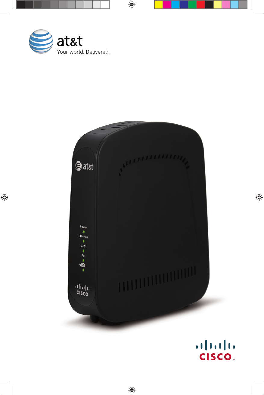
Welcome
Congratulations on purchasing the AT&T 3G MicroCell™. The MicroCell provides voice and data
service to AT&T 3G wireless phones and devices within a home or small business. The MicroCell
is secure and delivers maximum cellular signal strength within its coverage area – it’s like having
your own mini cell tower in your home or office for personalized coverage.
What’s Inside This Guide
This guide provides information and instructions for installing and operating the MicroCell. It
includes these topics:
• Getting Started
• Installation
• Activate Your Account
• MicroCell Status
• Device Status
• Operation
• Troubleshooting
• Antenna Descriptions
• Limited Hardware Warranty Terms
• FCC Compliance
• Radiation Exposure Statements
6
OCTOBER 24, 2008 DRAFT
Page 7
OCTOBER 24, 2008 DRAFT
Getting Started
Before You Begin
There are three things you must have before you can operate the MicroCell:
• Broadband service over DSL or Cable*
• Broadband modem or network router
• Computer with Internet access to register your device
Please verify these requirements before going any further.
Unpack
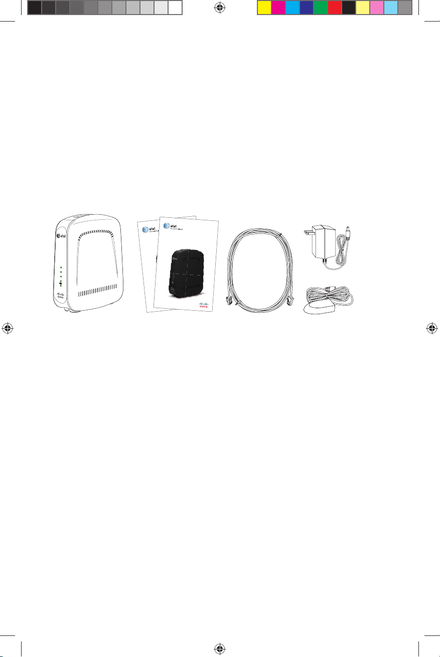
Remove the contents of the MicroCell package and verify that you received the following:
User Guide
AT&T 3G MicroCell™
Getting Started Guide
AT&T 3G MicroCell™
AC
Power
Adapter
Power
Ethernet
GPS
PC
GPS
Antenna
Extension
AT&T 3G
MicroCell
™
User Guide and
Getting Started Guide
Ethernet
Cable
(Packaged
Separately)
If anything is missing or appears to be damaged, contact Customer Support at 800.331.0500
for assistance.
* Downstream speeds of at least 1.5 Mbps and upstream speeds of at least 384 Kbps are recommended for best performance.
There are no restrictions on broadband service providers.
OCTOBER 24, 2008 DRAFT
7
Page 8

OCTOBER 24, 2008 DRAFT
Installation
The MicroCell is a plug-n-play device that installs in minutes. Connecting the MicroCell to your
pre-existing equipment is straight forward, but be sure to read the cabling instructions carefully
before making connections.
About Ethernet Cabling
There are two Ethernet cabling options for installing your device. Which one is right for you,
depends on the equipment setup you have.
• Option A: DSL/Cable Service with Router – You have DSL/Cable service, a broadband modem, and
a network router that supports a PC network. See page 9 for Ethernet cabling instructions.
• Option B: DSL/Cable Service without Router – You have DSL/Cable service and a broadband
modem that supports a single PC. See page 10 for Ethernet cabling instructions.
8
OCTOBER 24, 2008 DRAFT
Page 9

OCTOBER 24, 2008 DRAFT
5
DSL/Cable Service with Network Router
If a network router is part of your Internet equipment setup, the MicroCell should be installed
between the modem and network router.
Ethernet Cabling Procedures
• Place the MicroCell upright, near the modem, network router, and AC outlet.
• Turn off the modem, network router, and PC.
• Disconnect the Ethernet cable from the modem, while leaving the other end connected to the
network router.
• Reconnect the Ethernet cable to the black connector marked PC on the MicroCell.
• Find the Ethernet cable that shipped with the MicroCell. Connect one end to a free port on
the DSL/Cable modem and the other end to the yellow connector marked Ethernet on the
MicroCell.
• When you have finished cabling the system, turn on the modem first, the router second, and then the PC.
Note: Wait a few moments between turning on each device. This power-up sequence may be
critical for older devices.
Note: It is essential for the router to be connected to the PC port to ensure the best quality of
service on the MicroCell.
PC
ANT
PC
Ethernet
Reset
Power
AT&T 3G
MicroCell
Network
Router
™
OCTOBER 24, 2008 DRAFT
DSL/Cable
Modem
T1382
9
Page 10

OCTOBER 24, 2008 DRAFT
DSL/Cable Service without Network Router
If a network router is not part of your internet equipment setup, the MicroCell should be connected
between the modem and the PC.
Ethernet Cabling Procedures
• Place the MicroCell upright, near the modem and AC outlet.
• Disconnect the Ethernet cable from the modem, while leaving the other end connected to the
PC.
• Reconnect the Ethernet cable to the black connector marked PC on the MicroCell.
• Find the Ethernet cable that shipped with the MicroCell. Connect one end to the modem and the
other end to the yellow connector marked Ethernet on the MicroCell.
• When you have finished cabling the system, turn on the modem and the PC.
Note: It is essential for the PC to be connected to the PC port to ensure the best quality of
service on the MicroCell.
PC
ANT
10
PC
Ethernet
Reset
Power
AT&T 3G
MicroCell
™
OCTOBER 24, 2008 DRAFT
DSL/Cable
Modem
T13827
Page 11

OCTOBER 24, 2008 DRAFT
Power Cabling
Power cabling for the MicroCell is the same, no matter what your equipment configuration is.
The MicroCell uses house current from a 120VAC outlet.
• Connect one end of the AC adapter to the rear panel connector marked AC adapter.
• Connect the other end to the AC outlet.
That completes installation. The device is now ready to be registered.
ANT
PC
Ethernet
Reset
Power
AT&T 3G
MicroCell
AC Power
Adapter
™
Power
Outlet
T13830
OCTOBER 24, 2008 DRAFT
11
Page 12
OCTOBER 24, 2008 DRAFT
Activate Your Account
You must register your AT&T 3G MicroCell™ online before your service can be activated. Please
go to att.com/3GMicroCell, which will walk you through the following steps.
• Login and navigate to the Welcome page. It will provide helpful information on what you will
need to activate your service. Select “Set Up Your Device.”
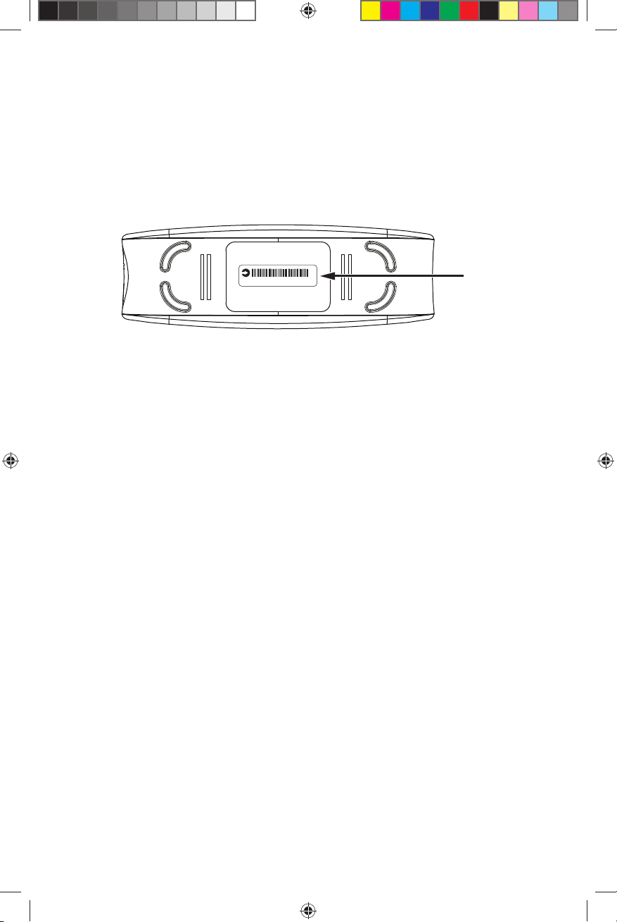
Step 1: Enter the serial number located on the bottom of your device. Please note that the serial
number is case sensitive. Select “Next.”
SN: ABCDEFGHIJKLMNO
Serial
Number
T13865
Step 2: Enter a nickname for your device, your email, and the street address where your device is
installed. This sets the location for E911 service*. Select “Next.”
Step 3: Set up your Approved User List. Enter the wireless numbers you would like to grant access to
your MicroCell. You can add more numbers at anytime, up to 10 in all. Select “Next.”
Step 4: Confirm AT&T 3G MicroCell™ Device Set Up Information—Review your account
information for accuracy, and Terms & Conditions. Select “Submit.”
Congratulations! You have completed your online registration.
• Visit att.com/3GMicroCell anytime to manage your device settings.
• After registering your device, it can take 10-30 minutes to activate. Service is available when
all MicroCell status LEDs turn green. If the Power LED stays red or if the 3G LED is still flashing
after 30 minutes, see Troubleshooting on page 16 for additional information.
*E911 Service: AT&T 3G MicroCell™ service is not available when either electrical service or your
broadband service is unavailable. You will not be able to access E911 service using your wireless
device unless you have service on AT&T’s wireless network from your home. The MicroCell unit
includes a GPS device that enables the unit to identify its location. The MicroCell will not work
until it has identified its location. If the MicroCell is moved to a new location, it is important that
instructions for updating the device location be followed to enable E911 service to function
properly.
12
OCTOBER 24, 2008 DRAFT
Page 13
OCTOBER 24, 2008 DRAFT
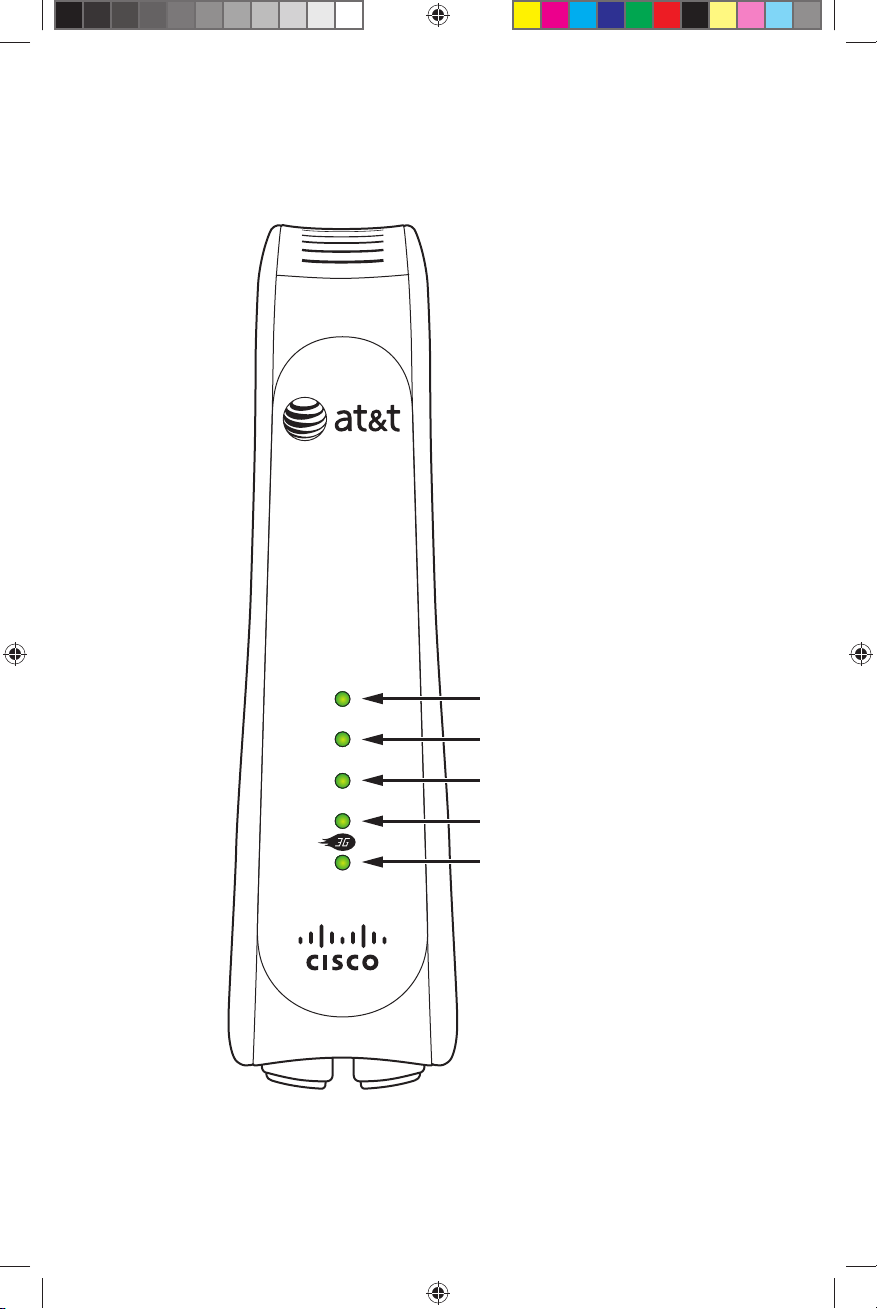
MicroCell Status
This diagram identifies the status LEDs on the MicroCell front panel.
T13822
Power
Ethernet
GPS
PC
OCTOBER 24, 2008 DRAFT
Power Status LED
Ethernet Status LED
GPS Status LED
PC Status LED
3G Status LED
13
Page 14

OCTOBER 24, 2008 DRAFT
This table describes how the status LEDs operate.
LED Indicator Color/State Description
Off No power.
Power
Ethernet
(Broadband
Connection)
GPS
PC
(PC/Router
Connection)
3G
(MicroCell
Connection)
Red/Steady*
Green/Steady Power is on and there are no faults.
Off* No connection.
Green/Steady Ethernet link.
Off Initial state.
Green/Flashing*
Green/Steady GPS ready.
Off
Green/Steady Ethernet activity.
Off No configuration and no MicroCell service.
Green/Flashing*
Red/Flashing*
Green/Steady MicroCell service available.
Power was just applied and the MicroCell is
initializing. If it persists, a fault has occurred.
Searching for GPS signal (part of first-time
authentication).
No connection. This is valid if you do not have a
have a PC or router, i.e., you only use the device for
MicroCell service.
Initialization is in process. Flashes may be short or
medium in length.
Fault condition(s) present that impact operation.
No MicroCell service.
*If any condition marked with an asterisk persists after 30 minutes, first see Troubleshooting on
page 16 for additional information. If you are still unable to resolve the problem, contact Customer
Support at 800.331.0500 for assistance.
Device Status
3G devices registered to access AT&T 3G MicroCell™ service on your MicroCell will display this
alpha tag when service is available:
AT&T MicroCell
If you do not see this alpha tag on your device, you are either out of range of the MicroCell or
your device isn’t registered (see Approved User List), or your MicroCell is not functioning properly
(see Troubleshooting on page 16 for additional information). If you are unable to resolve the
problem, contact Customer Support at 800.331.0500 for assistance.
14
OCTOBER 24, 2008 DRAFT
Page 15

OCTOBER 24, 2008 DRAFT
Operation
Performance Highlights
Here are some performance highlights for AT&T 3G MicroCell™ service using the MicroCell:
• Supports AT&T 3G wireless phones and devices
• Supports up to four simultaneous calls
• Supports hand out to the macro network
• Supports UMTS bands 2 & 5 (1900 MHz and 850 MHz)
What Happens When You Start Up the MicroCell?
Authentication
At startup, the MicroCell connects to the AT&T network using your Internet service. Then the AT&T
network authenticates the MicroCell and its location. The process takes from 10 to 30 minutes
to complete. If authentication succeeds, AT&T 3G MicroCell™ service is granted. If authentication
fails, service is denied.
GPS Satellite Link
First-time authentication in a new location requires a GPS (Global Positioning System) link with
the MicroCell.
• If the GPS link succeeds, authentication continues.
• If the GPS link fails, authentication is terminated. A failed GPS link is indicated by a flashing
green GPS LED on the front panel.
What Should You Do About a Failed GPS Link?
A GPS link will fail because of low signal strength at the MicroCell.
If the 3G LED is also flashing, authentication has failed. See Troubleshooting on page 16 for
steps you can take to fix the problem.
Note: You can still receive AT&T 3G MicroCell™ service when the GPS link is down as long as
the MicroCell has previously completed authentication. However, if you move your MicroCell to a
new address, it will need a GPS link again in order to complete authentication and receive AT&T
3G MicroCell™ service.
OCTOBER 24, 2008 DRAFT
15
Page 16

OCTOBER 24, 2008 DRAFT
Troubleshooting
Your AT&T 3G MicroCell™ has been engineered to provide continuous service without intervention
on your part. Occasionally, though, hardware faults and broadband service interruptions can occur
that disrupt the operation of the MicroCell. For these occasions, there are remedial troubleshooting
steps you can take to find the source of the problem and restore operation.
Note: When you suspect any disruption of service, always look at the MicroCell front panel status
LEDs first.
Hardware Problems
If… Then…
The MicroCell is not getting AC power.
• Make sure the AC adapter is securely connected between the
The Power LED
is off.
The Power LED
is red.
The GPS LED is
flashing after
30 minutes.
MicroCell power connector and AC outlet or power strip (see
the power cabling diagram on page 11).
• Make sure there are no faults in the power strip or in the
building’s power system.
A hardware fault on the MicroCell has occurred.
• Recyle power on the MicroCell (disconnect and reconnect power
to the unit) to restart initialization.
• If the Power LED stays red, contact Customer Support at
800.331.0500 for assistance.
The MicroCell cannot detect a GPS signal.
• This condition usually occurs because the MicroCell is too far
from a window, or is in a windowless room. This is a problem
if the MicroCell has not previously completed first-time
authentication (see GPS Satellite Link on page 15 for more
information).
• To fix:
1. Disconnect power and Ethernet cabling.
2. Move the MicroCell to a window.
3. Reconnect power and wait 10-30 minutes for the GPS link.
4. When the GPS LED turns to steady green, the MicroCell has
the link it needs to continue with first-time authentication.
5. Allow the process to continue until the 3G LED turns to steady
green. Then move the unit back to its original position and
re-cable.
Note: You must re-connect power within 20 minutes or the
MicroCell will lose the GPS data and the entire procedure will
need to be repeated.
• An alternative solution is to install the optional GPS antenna
extension (see Antenna Descriptions on page 18 for more
information and installation instructions).
16
OCTOBER 24, 2008 DRAFT
Page 17

Hardware Problems, continued
If… Then…
There is no physical connection between the MicroCell and the
broadband modem.
The Ethernet LED
is off.
• Make sure an Ethernet cable is securely connected between
the broadband modem and the MicroCell rear panel connector
marked Ethernet (see the Ethernet Cabling diagrams on pages
9 and 10).
OCTOBER 24, 2008 DRAFT
The PC LED
is off.
The 3G LED is off.
The 3G LED is green/
flashing (short pulses).
The 3G LED is green/
flashing (even pulses).
The 3G LED is
red/flashing.
There is no physical connection to the PC network.
• Make sure the PC or network router is connected to this port
(see the Ethernet Cabling diagrams on pages 9 and 10).
There is no configuration. In this case the Power LED may also be
red.
• To fix, recycle power on the MicroCell to restart initialization.
• If the condition does not clear, contact Customer Support at
800.331.0500 for assistance.
Configuration is in process.
• If this condition persists, the ISP is not responding.
• To fix, recycle power on the broadband modem and wait several
minutes for the condition to clear.
• If the condition does not clear, contact your ISP for assistance.
Configuration has completed, but, a connection has not been opened
with the AT&T Network.
• If the condition persists, recycle power on the MicroCell and wait
for the condition to clear.
• If the condition doesn’t clear, contact Customer Support at
800.331.0500 for assistance.
Faults are present on the MicroCell that impact service.
• The Power LED may be red. If so, take steps to clear this condition.
• GPS LED may be flashing. If so, take steps to clear this condition.
OCTOBER 24, 2008 DRAFT
17
Page 18

Service Problems
If… Then…
The PC network
performance declines.
OCTOBER 24, 2008 DRAFT
Traffic across the MicroCell has risen to a critical level.
• Check for unusually heavy data requests (video downloads are
likely suspects) and limit them, if possible.
• If the decline is chronic, consider upgrading service.
A 3G device is unable
to access the AT&T 3G
MicroCell
Callers are having
trouble making calls
on the AT&T 3G
MicroCell
™
service.
™
service.
The device may not be registered (see Activate Your Account on
page 12 and follow the instructions on how to access your account
and register 3G devices).
The MicroCell may be serving a full load of calls.
The MicroCell can support up to four simultaneous calls.
Antenna Descriptions
The MicroCell has one antenna for cellular signals and another for GPS signals. If GPS signal
strength is too low, a port for connecting an optional GPS antenna extension is also available.
All three are described below:
Cellular Antenna
The cellular antenna is mounted inside the MicroCell enclosure and is for transceiving cellular
traffic with registered 3G devices. The maximum range of the AT&T 3G MicroCell™ is approximately
5000 square feet. Actual range will be limited by the density of obstructions.
GPS Antenna
The GPS (Global Positioning System) antenna is mounted inside the MicroCell enclosure and is
for receiving GPS signals. It cannot be adjusted, but has enough gain in most instances to detect
signals in any room with a window.
If the GPS link is unreliable (indicated by a flashing GPS status LED), try the following procedure:
• Move the MicroCell closer to a window.
• Recycle power on the MicroCell to restart authentication.
• You’ll know if the effort was successful if the GPS status LED turns to steady green.
If this procedure fails, try installing the optional GPS antenna extension.
18
OCTOBER 24, 2008 DRAFT
Page 19

OCTOBER 24, 2008 DRAFT
GPS Antenna Extension Installation
• Plug one end of the device into the GPS antenna extension connector and place the other end
as close as possible to the nearest window.
• Recycle power on the MicroCell to restart authentication.
• If the extension is successful, the GPS status LED will turn to steady green in 10 to 30 minutes. You
must then allow authentication to continue until the 3G status LED turns to steady green.
• Disconnect the GPS antenna extension when you’re done and store it in a safe place.
If this procedure fails, contact Customer Support at 800.331.0500 for assistance.
ANT
PC
Ethernet
Reset
Power
Reset Button
GPS Antenna
Extension
AT&T 3G
MicroCell
™
T13884
Note: Pressing the Reset button restores the MicroCell to its factory default settings. Do not press
the Reset button unless you have been asked to by Customer Support.
OCTOBER 24, 2008 DRAFT
19
Page 20

OCTOBER 24, 2008 DRAFT
AT&T Warranty Terms
20
OCTOBER 24, 2008 DRAFT
Page 21

OCTOBER 24, 2008 DRAFT
OCTOBER 24, 2008 DRAFT
21
Page 22

FCC Compliance
OCTOBER 24, 2008 DRAFT
United States FCC Compliance
This device has been tested and found
to comply with the limits for a Class B
digital device, pursuant to part 15 of the
FCC Rules. These limits are designed to
provide reasonable protection against such
interference in a residential installation. This
equipment generates, uses, and can radiate
radio frequency energy. If not installed and
used in accordance with the instructions,
it may cause harmful interference to radio
communications. However, there is no
guarantee that interference will not occur
in a particular installation. If this equipment
does cause harmful interference to radio or
television reception, which can be determined
by turning the equipment OFF and ON, the
user is encouraged to try to correct the
interference by one or more of the following
measures:
• Reorient or relocate the receiving antenna,
if applicable.
• Increase the separation between the
equipment and receiver.
• Connect the equipment into an outlet on
a circuit different from that to which the
receiver is connected.
• Consult the cable company or an
experienced radio/television technician
for help.
Any changes or modifications not expressly
approved by Cisco Systems, Inc., could
void the user’s authority to operate the
equipment.
The information shown in the FCC Declaration
of Conformity paragraph below is a
requirement of the FCC and is intended to
supply you with information regarding the
FCC approval of this device. The phone
numbers listed are for FCC-related questions
only and not intended for questions regarding
the connection or operation for this device.
Please contact your cable service provider
for any questions you may have regarding
the operation or installation of this device.
Declaration of Conformity
This device complies with Part 15 of FCC
Rules. Operation is subject to the following
two conditions: 1) the device may not cause
harmful interference, and 2) the device must
accept any interference received, including
interference that may cause undesired
operation.
AT&T 3G MicroCell™
Model: MicroCell
Manufactured by: Cisco Systems, Inc.
5030 Sugarloaf Parkway
Lawrenceville, Georgia 30044 USA
Telephone: 770-236-1077
Canada EMI Regulation
This Class B digital apparatus complies with
Canadian ICES-003.
Cet appareil numérique de la class B est
conforme à la norme NMB-003 du Canada.
20060628 FCC Standard
Software and Firmware Use
The software described in this document is
protected by copyright law and furnished to
you under a license agreement. You may only
use or copy this software in accordance with
the terms of your license agreement.
The firmware in this equipment is protected
by copyright law. You may only use the
firmware in the equipment in which it is
provided. Any reproduction or distribution of
this firmware, or any portion of it, without our
express written consent is prohibited.
Disclaimer
Cisco Systems, Inc. assumes no responsibility
for errors or omissions that may appear in this
guide. We reserve the right to change this
guide at any time without notice.
22
OCTOBER 24, 2008 DRAFT
Page 23
OCTOBER 24, 2008 DRAFT
Radiation Exposure Statements
Note: This transmitter must not be co-located or operated in conjunction with any other antenna
or transmitter. This equipment should be installed and operated with a minimum distance of 7.9
inches (20 cm) between the radiator and your body.
United States
This system has been evaluated for RF exposure for humans in reference to ANSI C 95.1 (American
National Standards Institute) limits. The evaluation was based on evaluation per ANI C 95.1 and
FCC OET Bulletin 65C rev 01.01. The minimum separation distance from the antenna to general
bystander is 7.9 inches (20 cm) to maintain compliance.
Canada
This system has been evaluated for RF exposure for humans in reference to ANSI C 95.1 limits.
The evaluation was based on evaluation per RSS-102 Rev 2. The minimum separation distance
from the antenna to general bystander is 7.9 inches (20 cm) to maintain compliance.
OCTOBER 24, 2008 DRAFT
23
Page 24

OCTOBER 24, 2008 DRAFT
Cisco Systems, Inc. 678.277.1000
5030 Sugarloaf Parkway, Box 465447
Lawrenceville, GA 30042 www.scientificatlanta.com
Cisco, Cisco Systems, the Cisco logo, the Cisco Systems logo, and Scientific Atlanta are registered trademarks or trademarks of Cisco Systems, Inc. and/or its
affiliates in the United States and certain other countries.
AT&T, the AT&T logo, and AT&T 3G MicroCell are trademarks of AT&T Intellectual Property.
All other trademarks mentioned in this document are the property of their respective owners.
Product and service availability is subject to change without notice.
© 2008 Cisco Systems, Inc. All rights reserved.
October 2008 Printed in United States of America Part Number 4011762 Rev A
OCTOBER 24, 2008 DRAFT
 Loading...