

Page 1

Gemtek Technology Co., Ltd.
WX-1516
Hot Spot Access Point
User's Manual
Apr. 20, 2003 (Draft 1.0)
1
Page 2

Contents
4
4
4
4
5
6
6
7
7
8
8
8
9
9
10
11
11
11
12
12
12
13
14
14
14
15
15
15
15
16
17
17
18
18
18
1
1.1
1.2
1.3
1.4
1.4.1
1.4.2
1.4.3
1.4.4
2
2.1
2.2
2.3
2.4
2.5
2.6
2.6.1
2.6.2
2.7
2.8
2.8.1
2.8.2
3
3.1
3.2
3.3
3.4
3.4.1
3.4.2
3.4.3
3.4.4
3.4.5
3.4.6
3.4.7
3.4.8
Getting started . . . . . . . . . . . . . . . . . . . . . . . . . . . . . . . . . . .
Introduction . . . . . . . . . . . . . . . . . . . . . . . . . . . . . . . . . . . . . . . . . . . . .
Contents of this manual . . . . . . . . . . . . . . . . . . . . . . . . . . . . . . . . . . . . .
Wireless networking basics and advantages . . . . . . . . . . . . . . . . . . . . .
Adding Access Points to your (network) environment . . . . . . . . . . . . . .
Connecting an Access Point directly to a computer . . . . . . . . . . . . . . . .
Extending a wired network with one or more Access Points . . . . . . . .
Creating a wireless network . . . . . . . . . . . . . . . . . . . . . . . . . . . . . . . . .
Creating a gateway . . . . . . . . . . . . . . . . . . . . . . . . . . . . . . . . . . . . . . .
Installing the Access Point . . . . . . . . . . . . . . . . . . . . . . . .
Introduction . . . . . . . . . . . . . . . . . . . . . . . . . . . . . . . . . . . . . . . . . . . . .
Access Point environment . . . . . . . . . . . . . . . . . . . . . . . . . . . . . . . . . .
Physical installation of the Access Point . . . . . . . . . . . . . . . . . . . . . . .
Desktop installation . . . . . . . . . . . . . . . . . . . . . . . . . . . . . . . . . . . . . . .
Wall mount installation . . . . . . . . . . . . . . . . . . . . . . . . . . . . . . . . . . . . .
Connecting the Access Point . . . . . . . . . . . . . . . . . . . . . . . . . . . . . . . .
Power adapter . . . . . . . . . . . . . . . . . . . . . . . . . . . . . . . . . . . . . . . . . . .
Ethernet port . . . . . . . . . . . . . . . . . . . . . . . . . . . . . . . . . . . . . . . . . . . .
LEDs . . . . . . . . . . . . . . . . . . . . . . . . . . . . . . . . . . . . . . . . . . . . . . . . . .
The reset button . . . . . . . . . . . . . . . . . . . . . . . . . . . . . . . . . . . . . . . . . .
Unlocking the Access Point . . . . . . . . . . . . . . . . . . . . . . . . . . . . . . . . .
Resetting to the default factory settings . . . . . . . . . . . . . . . . . . . . . . . .
Connecting to the Access Point . . . . . . . . . . . . . . . . . . .
Introduction . . . . . . . . . . . . . . . . . . . . . . . . . . . . . . . . . . . . . . . . . . . . .
When to configure the Access Point . . . . . . . . . . . . . . . . . . . . . . . . . .
Starting the Web Interface . . . . . . . . . . . . . . . . . . . . . . . . . . . . . . . . . .
Using KickStart . . . . . . . . . . . . . . . . . . . . . . . . . . . . . . . . . . . . . . . . . . .
Installing KickStart . . . . . . . . . . . . . . . . . . . . . . . . . . . . . . . . . . . . . . . .
Launching KickStart . . . . . . . . . . . . . . . . . . . . . . . . . . . . . . . . . . . . . . .
Select wireless ethernet device . . . . . . . . . . . . . . . . . . . . . . . . . . . . . .
Change IP settings . . . . . . . . . . . . . . . . . . . . . . . . . . . . . . . . . . . . . . . .
Static IP settings . . . . . . . . . . . . . . . . . . . . . . . . . . . . . . . . . . . . . . . . .
Set Gateway address . . . . . . . . . . . . . . . . . . . . . . . . . . . . . . . . . . . . . .
Changing IP settings . . . . . . . . . . . . . . . . . . . . . . . . . . . . . . . . . . . . . .
Ready to start the Web Interface . . . . . . . . . . . . . . . . . . . . . . . . . . . . .
2
Page 3

3.5
19
19
21
21
21
22
24
25
26
27
28
28
29
29
30
32
33
33
33
34
34
35
35
36
37
38
39
45
46
47
3.6
4
4.1
4.2
4.3
4.4
4.5
4.6
4.7
4.8
4.8.1
4.8.2
4.9
4.9.1
4.9.2
5
5.1
5.2
5.3
5.4
5.5
5.6
5.6.1
5.6.2
5.6.3
5.6.4
5.7
5.8
6
Launching the Web Interface directly . . . . . . . . . . . . . . . . . . . . . . . . . .
Contents of the Web Interface . . . . . . . . . . . . . . . . . . . . . . . . . . . . . . . .
Basic configuration . . . . . . . . . . . . . . . . . . . . . . . . . . . . . .
Introduction . . . . . . . . . . . . . . . . . . . . . . . . . . . . . . . . . . . . . . . . . . . . . .
IP addressing . . . . . . . . . . . . . . . . . . . . . . . . . . . . . . . . . . . . . . . . . . . .
Connecting an Access Point directly to a computer . . . . . . . . . . . . . . .
Extending a wired network with one or more Access Points . . . . . . . . .
Creating a wireless network . . . . . . . . . . . . . . . . . . . . . . . . . . . . . . . . .
Creating a gateway . . . . . . . . . . . . . . . . . . . . . . . . . . . . . . . . . . . . . . . .
Using a DHCP server . . . . . . . . . . . . . . . . . . . . . . . . . . . . . . . . . . . . . .
Adding multiple Access Points to a network . . . . . . . . . . . . . . . . . . . . .
Connecting Access Points via Ethernet links . . . . . . . . . . . . . . . . . . . .
Connecting Access Points via wireless links . . . . . . . . . . . . . . . . . . . . .
Network Setup in general . . . . . . . . . . . . . . . . . . . . . . . . . . . . . . . . . . .
WAN Connection . . . . . . . . . . . . . . . . . . . . . . . . . . . . . . . . . . . . . . . . . .
LAN settings . . . . . . . . . . . . . . . . . . . . . . . . . . . . . . . . . . . . . . . . . . . . .
Advanced configuration . . . . . . . . . . . . . . . . . . . . . . . . . .
Introduction . . . . . . . . . . . . . . . . . . . . . . . . . . . . . . . . . . . . . . . . . . . . . .
Settings Summary . . . . . . . . . . . . . . . . . . . . . . . . . . . . . . . . . . . . . . . . .
Event reporting/logging . . . . . . . . . . . . . . . . . . . . . . . . . . . . . . . . . . . . .
Identifying the Access Point . . . . . . . . . . . . . . . . . . . . . . . . . . . . . . . . .
Wireless Settings . . . . . . . . . . . . . . . . . . . . . . . . . . . . . . . . . . . . . . . . . .
Security . . . . . . . . . . . . . . . . . . . . . . . . . . . . . . . . . . . . . . . . . . . . . . . . .
Security against unauthorized network access . . . . . . . . . . . . . . . . . .
Security against eavesdropping . . . . . . . . . . . . . . . . . . . . . . . . . . . . . .
Security against unauthorized configuration . . . . . . . . . . . . . . . . . . . . .
Firewall . . . . . . . . . . . . . . . . . . . . . . . . . . . . . . . . . . . . . . . . . . . . . . . .
Port forwarding . . . . . . . . . . . . . . . . . . . . . . . . . . . . . . . . . . . . . . . . . . .
Upgrading the Access Point firmware . . . . . . . . . . . . . . . . . . . . . . . . . .
Troubleshooting . . . . . . . . . . . . . . . . . . . . . . . . . . . . . . . .
Federal Communication Commission Interference tatement …………....51
R&TTE Compliance tatement ………………………………………….… .……52
3
Page 4

1 Getting started
1.1 Introduction
Thank you for purchasing your 11 Mbps WLAN Access Point.
The package you have received contains the following items:
˙user manual
˙11 Mbps WLAN Access Point
˙power adapter
˙CD containing configuration software and this manual
1.2 Contents of this manual
Table 1-1 Contents of this manual
Chapter When to read:
This chapter (Getting Started) Read this chapter for general information on wireless networks.
Chapter 2: ‘Installing the
Access Point’ on page 8
Chapter 3: ‘Connecting to the Access
Point ’on page 14
Chapter 4: ‘Basic
Configuration’ page 20
Chapter 5: ‘Advanced
Configuration’ on page 31
Chapter 6: ‘Trouble shooting’ on page
43
Read this for information on how to install and connect the Access
Point to your (network) environment.
Read this chapter when you want to connect to an Access Point to
configure it.
Read this chapter when you want to configure the Access Point for
use in common situations (the ones listed in section 1. 4: ‘Adding
Access Points to your (network) environment’).
Read this chapter when you want to make full use of the Access
Point’s advanced capabilities.
Read this chapter when the Access Point does not function
properly.
1.3 Wireless networking basics and advantages
A wireless network connects computers to each other using radio
technology. This offers you the freedom to move around the area
and work anywhere within range of an Access Point. Such a wireless
network is called a WLAN (Wireless Local Area Network).
Access Points can be connected to a wired (Ethernet) network. This
allows wireless clients to communicate with computers on the wired
network. This type of network is called a LAN (Local Area Network).
An Access Point can also act as a gateway. You can connect the
4
Page 5

Access Point to your internet connection (for example a cable modem
or ADSL modem), and use the wireless LAN to connect your
computers to the internet. The internet, or any other network outside
the gateway, is called a WAN (Wide Area Network).
1.4 Adding Access Points to your (network) environment
Where to place and how to connect an Access Point depends
entirely on your specific (network) environment. The
following sections give some guidelines on how to add Access
Points to your environment.
An Access Point can be used to:
˙connect to a single computer (see section 1.4.1)
˙extend an existing wired network (see section 1.4.2)
˙create a wireless network (see section 1.4.3)
˙create a gateway to the internet (see section 1.4.4)
These are not the only ways you can use an Access Point. You
can adapt these basic scenarios for use in your network
environment.
The scenarios listed below are described in more detail in
chapter 4: ‘Basic configuration’
The Access Point also has a number of advanced functions.
These are not required for the Access Point to function, but
are optional. These functions are described in chapter 5:
‘Advanced configuration’.
5
Page 6
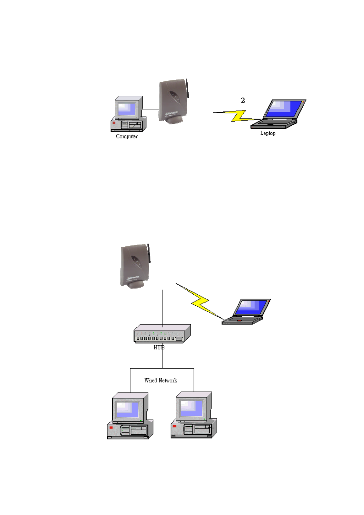
1.4.1 Connecting an Access Point directly to a computer
You can connect an Access Point directly to your computer.
Figure 1-2 Connecting an Access Point directly to a computer
You need to use a crossover cable to connect the Access Point
directly to your computer.
1.4.2 Extending a wired network with one or more Access Po ints
You can extend existing wired networks with wireless capability by
adding Access Points to them.
Figure 1-3 Adding an Access Point to a wired network
6
Page 7
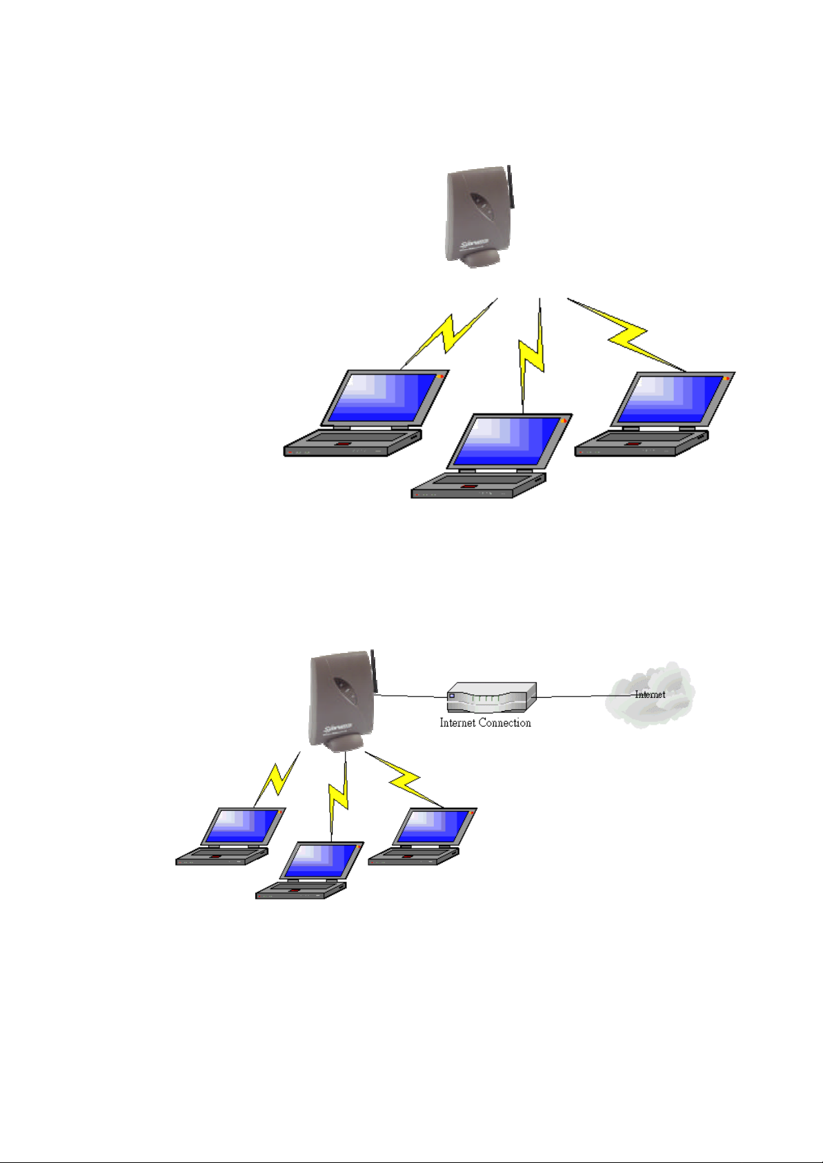
1.4.3 Creating a wireless network
You can use an Access Point to set up a wireless network.
Figure 1-4 Wireless network
1.4.4 Creating a gateway
You can use an Access Point to set up a gateway to the internet.
Figure 1-5 Wireless network with internet gateway
7
Page 8

2 Installing the Access Point
2.1 Introduction
This chapter describes the physical installation of an Access Point.
Table 2-1 Overview of this chapter
Section Describes
2.2 Where to install an Access Point
2.3, 2.4, 2.5 How to install an Access Point.
2.6 How to connect the AccessPoint.
2.7 Explanation of the LEDs.
2.8 How to unlock/reset the Access Point.
2.2 Access Point environment
When you install an Access Point, you must consider the following
items:
˙connection to a power outlet
.
˙connection to the network
˙environment of the Access Point (heat/humidity)
˙range of the Access Point
8
Page 9
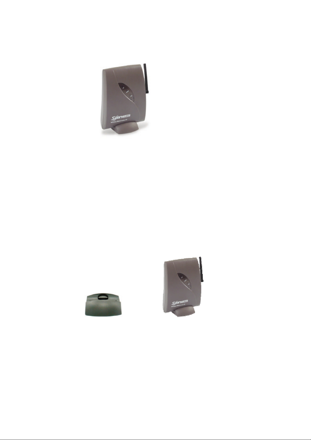
2.3 Physical installation of the Access Point
For best performance, install the Access Point in a vertical position.
Figure 2-1 The Access Point
The Access Point can be installed in 2 different ways:
˙on a desktop
˙mounted to a wall
The stand is used for desktop placement.
2.4 Desktop installation
Determine where you want to place the Access Point. Make sure you
have a clear area on a desktop.
You can insert the Access Point into the stand as shown in Figure 2-2.
Figure 2-2 Access Point for desktop use
No mounting materials are requir ed
9
Page 10
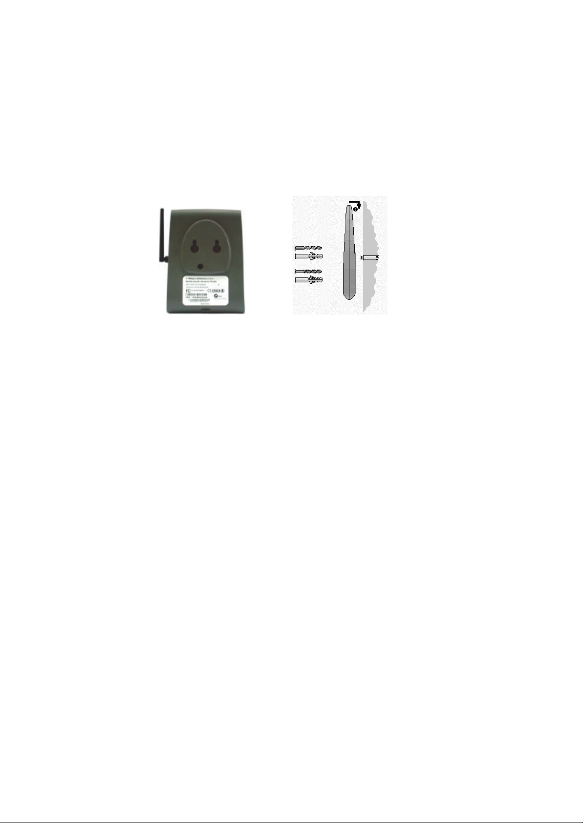
2.5 Wall mount installation
Note: Before you start drilling holes into a wall, make sure that part
of the wall is clear of electricity, water and gas pipes.
The wall mount package contains two screws and plugs to fasten the
Access Point to the wall.
1
○
Figure 2-3 Mounting the Access Point on a wall
Step by step wall mount installation:
1. Determine the position of the screws. The screws must be 5 cm apart
to fit the keyholes at the back of the Access Point.
2. Drill the holes in the wall (at the appropriate size for the plugs).
3. Insert the plugs into the holes.
4. Fasten the screws into the plugs, and leave about 3 mm of space
between wall and screw head.
5. Attach the Access Point to the screws: there are two keyholes ○1 in
the back of the Access Point. The screwheads fit into the large half of
the keyholes. Once the screwheads are inside the keyholes, the
Access Point can drop ○2, locking the screwheads into the small half
of the keyholes.
10
Page 11
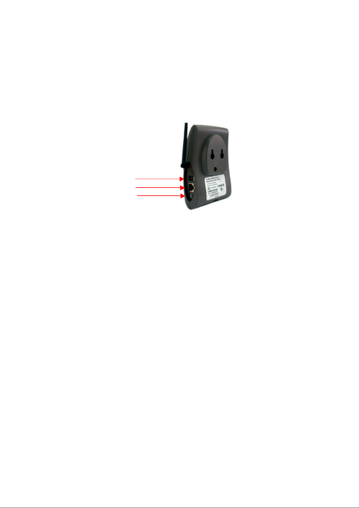
2.6 Connecting the Access Point
Your Access Point is now ready to be connected to a power outlet and
to your wired network.
You can find the power input and the Ethernet port on the left hand
side of the Access Point.
Power
Ethernet Port
Reset
Figure 2-4 Connecting the Access Point
2.6.1 Power adapter
The Access Point package contains a power adapter. To connect it:
1. Plug it into the Access Point.
2. Plug the power cord into the adapter.
3. Plug the power cord into a power outlet.
4. Check the power LED (the middle of the three LEDs). If it is ON,
you are connected properly.
2.6.2 Ethernet port
The Ethernet port (an RJ45 socket) can be found next to the power
connector on the Access Point.
For a wired connection, attach the Ethernet cable to the Access Point
and connect the cable on the other end to either a hub in the network,
or a computer.
If you want to connect to an Access Point via a wired connection, it
must be connected correctly:
˙if the Access Point is connected to a hub or switch, a ‘Normal’ (not
a crossover) cable must be used
˙if the Access Point is connected directly to a computer, a crossover
11
Page 12
cable must be used
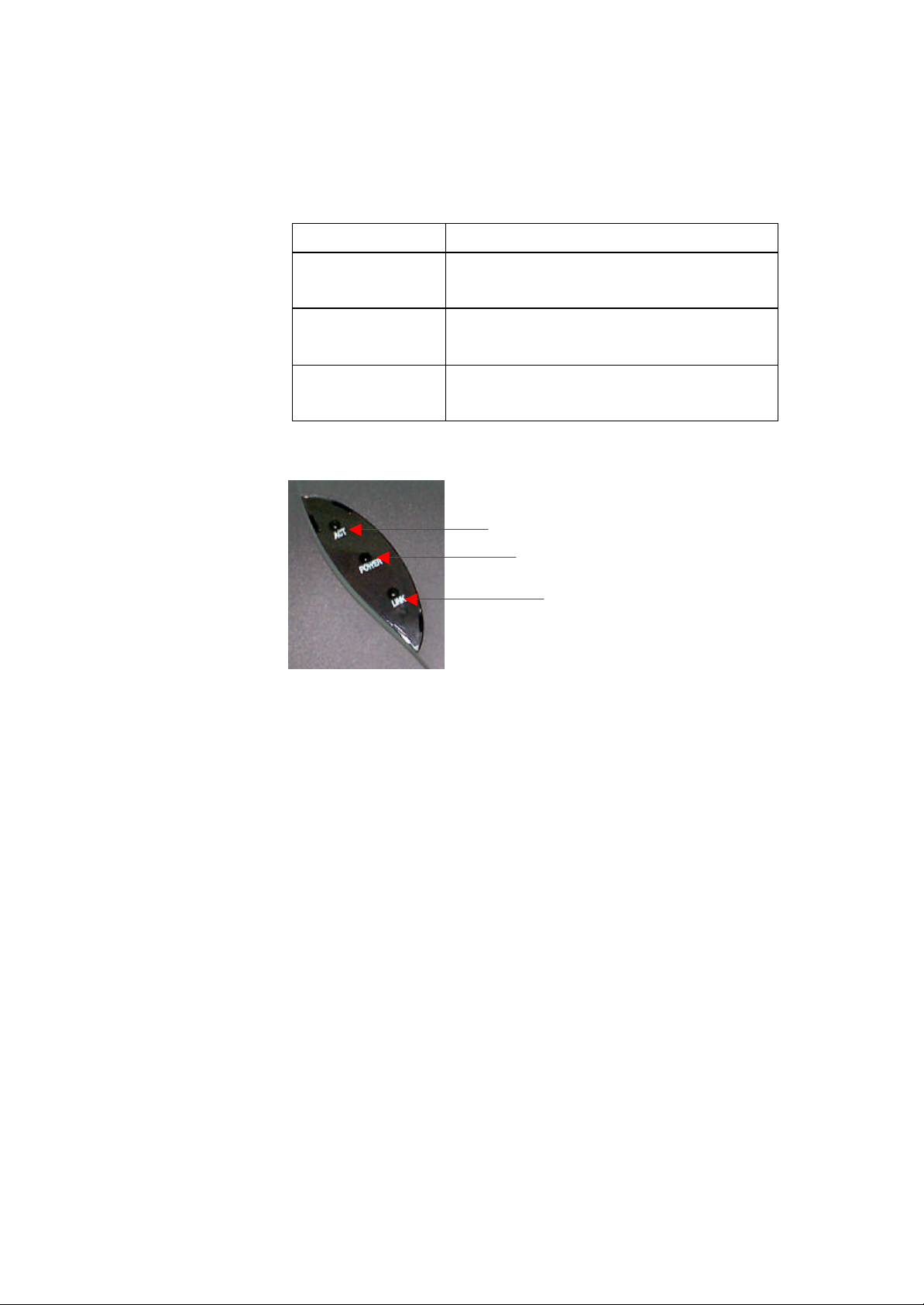
2.7 LEDs
The Access Point has three LEDs
Table 2-2 LEDs
LED LED Function
Link The link LED is on when the Access
Power The power LED is on when the Access
Point is connected to a wired network.
Point is connected to the electricity net.
ACT
(Radio signal)
Figure 2-5 shows the LEDs.
Figure 2-5 Access Point LEDs
2.8 The reset button
The unlock/reset button is found beneath the power and Ethernet
ports. It is a small hole that gives access to a pushbutton switch.
You can use this button in two ways: to unlock or to reset the
The ACT LED blinks when the Access
Point is active.
ACT
Power
Link
Access Point. Unlocking makes the Access Point accessible for
configuration changes. Resetting removes all settings you made.
2.8.1 Unlocking the Access Point
Doing this unlocks the Access Point (i.e. the Lock Access Point
setting) and removes the WCS (Write Community String) password.
These settings are described in section 5.6.3: ‘Security against
unauthorized configuration’.
1. Insert the end of a paperclip into the hole.
2. Press the button until the Radio LED (the one on the right) goes
from blinking to being on constantly. This takes about one
second.
12
Page 13

3. Release the reset button when the LED is o n constantly.
You can now use the Web Interface to manage the Access Point
again.
2.8.2 Resetting to the default factory settings
If you press the reset button for more than 5 seconds, the Access
Point will be reset to the default factory settings.
All changes you made to the configuration will be lost.
1. Insert one end of a paperclip into the hole for the reset button
and keep it pressed for more than five seconds. After about one
second, the Radio LED (the one on the right) goes from
blinking to being on constantly. After about five seconds, the
LED goes off.
2. Release the reset button when the LED has gone off.
All settings are deleted. You will need to reconfigure the Access
Point.
13
Page 14

3 Connecting to the Access Point
3.1 Introduction
The Access Point is a ready to use device. It is delivered with default
settings which allow you to use its basic functions without
configuring it.
Whether you need to configure the Access Point or not, depends
entirely on how you use the Access Point in your network
environment. Section 3.2: ‘When to configure the Access Point’
discusses the consequences of configuring the Access Point.
You configure the Access Point via Web pages that are built into the
Access Point. These are accessible via any Web browser. The
KickStart application helps you access this Web Interface.
Table 3-1 Overview of this chapter
Section Description
3.2 When to configure the Access Point
3.3-3.4 Starting the Web Interface
3.5 Launching the Web Interface manually
3.6 Contents of the Web Interface
3.2 When to configure the Access Point
Configuring the Access Point means installing settings with respect to
the use of radio channels, security, identification, etc.
Out of the box, the Access Point is configured so you can use it as a
basic Access Point (a “Hub” for your wireless network).
In scenarios like section 1.4.1: ‘Connecting an Access Point directly
to a computer’ where there’s no gateway, the Access Point will
probably function without additional configuration. If it doesn’t, you
need to change the IP address settings.
14
Page 15

Not configuring your Access Point will make your network accessible
to anyone. Once your network is up and running, we recommend you
read section 5.6: ‘Security’ and secure your network.
When you want to use the more advanced functions (e.g. use the
Access Point as a gateway to the internet), you need to change the
configuration.
3.3 Starting the Web Interface
The first time you want to access the Web Interface, you need to use
KickStart to find it. For subsequent access, you can go to the Web
Interface directly (see section 3.5) and you don’t need KickStart.
Tip: you can bookmark the web address for the Web Interface for even
easier access.
You also need to use KickStart after you have reset the Access Point to
factory defaults.
3.4 Using KickStart
KickStart helps you start the Web Interface: it finds all Access Points in
your network and it points your Web browser to the Web Interface of
the Access Point you selected.
If your network uses DHCP or Auto IP to assign IP addresses,
KickStart retrieves the address assigned to the Access Point.
If your network uses static IP addresses, KickStart allows you to
change the IP address settings for an Access Point.
3.4.1 Installing KickStart
You can install KickStart on any PC in the network to which the
Access Point will be connected. Follow the instructions of the
installation wizard.
3.4.2 Launching KickStart
Launch KickStart via the Start menu. The application starts up.
When you click Next, KickStart will search for all Access Points
within range, whether they have been configured properly or not.
15
Page 16
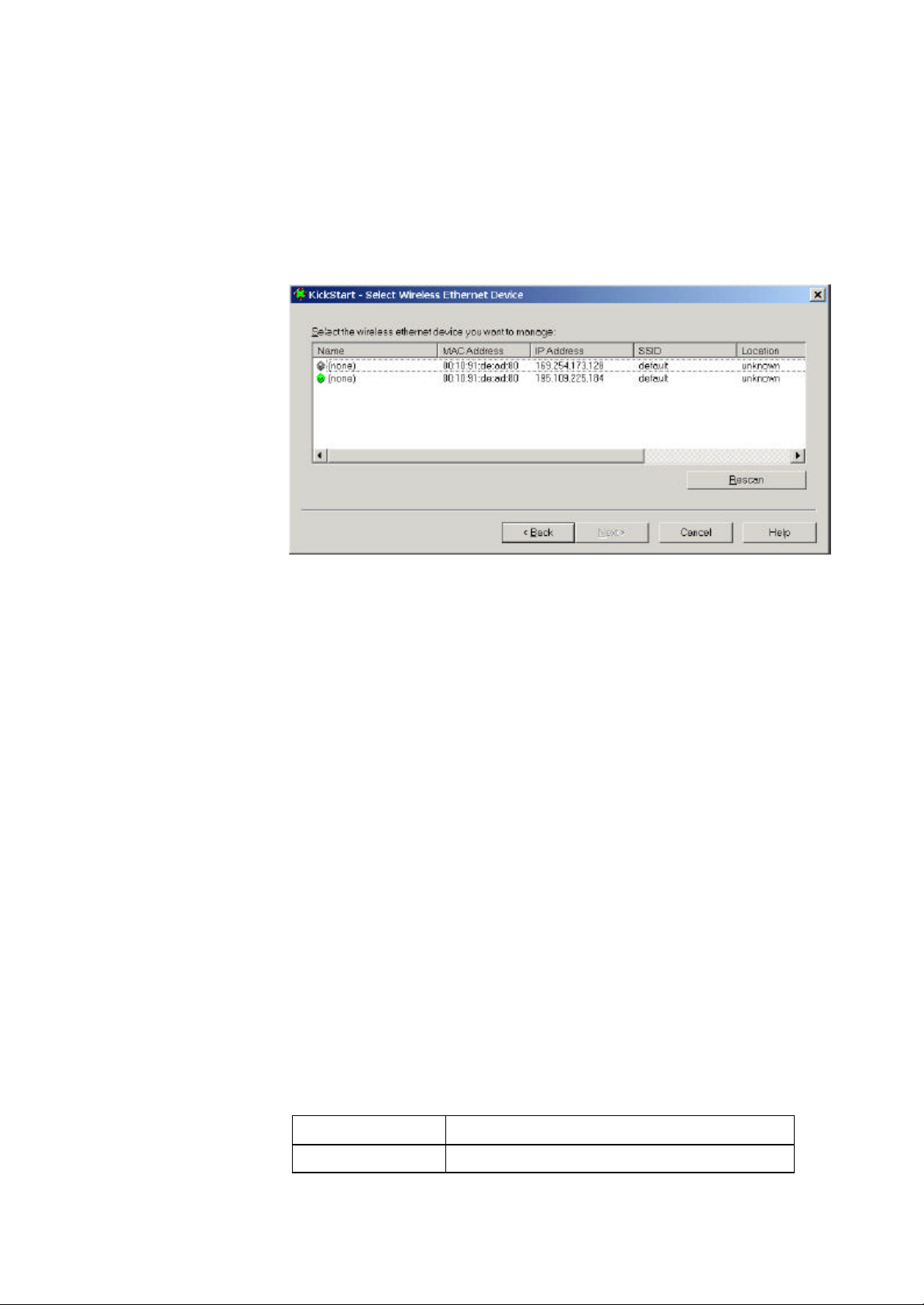
3.4.3 Select wireless ethernet device
In the ‘Select wireless ethernet device’ dialog, select the Access
Point you want to configure from the list. Once you have selected
an Access Point, click Next to continue.
Figure 3-1 KickStart: ‘Select wireless ethernet device’ dialog
If the Access Point you are looking for does not appear in the list,
click Rescan. KickStart will search for Access Points again. For
example, use this to find Access Points that have just been
switched on or reset. These devices may take up to a minute to
find an IP address, and they won’t appear in the list until then.
If the device that you want to manage is not in the list and is not
found after clicking the Rescan button, go to chapter 6:
‘Troubleshooting’.
An Access Point may appear twice in the list: you? l see two
items with the same MAC address, but different IP addresses. In
this case, select the one with the green icon.
The columns in the list contain the properties of all detected
wireless devices. Table 3-2 lists these properties:
Table 3-2 Description of the device data
Column Description
Name The name of the Access Point. This cannot
16
Page 17

be changed. The icon that precedes the
name can be gray or green.
A gray icon means that the Access Point’s IP
address needs to be changed: it is not in the
same subnet as your computer. For more
information on subnets.
A green icon means the Access Point’s IP
address does not need to be changed.
MAC address Every Ethernet device has a unique address
that is permanently linked to that device. It
cannot be changed. On most wireless
devices, the MAC address is printed on its
type label.
IP address
SSID The SSID is also known as Service Set ID.
Location
Contact The name of the contact person for the
3.4.4 Change IP settings
In the ‘Change IP Settings’ dialog you can select to use either
dynamic or static IP settings.
In order to access a TCP/IP network, a
device must have an IP address in addition
to its MAC address.
This is the name of your wireless network.
The location of the Access Point.
See section 5.4: ‘Identifying the Access
Point’ on how to edit this field.
Access Point.
See section 5.4: ‘Identifying the Access
Point’ on how to edit this field.
Select Dynamic IP settings when you install the Access Point in a
network with an external DHCP server or Auto IP.
Select Static IP settings when you want to configure the IP
settings manually. You also need to do this if you want to use the
DHCP server that is built into the Access Point.
Click Next to continue to the next screen.
17
Page 18

˙If you selected the option Use dynamic IP settings, you will
continue to the ‘Changing IP settings ’ dialog directly. see section
˙If you selected the option Use static IP settings, you will
continue to the ‘Set IP address of Wireless Device’ dialog, see
section 3.4.5.
3.4.5 Static IP settings
If you selected the option Use static IP setting in the ‘Change IP
Settings’ dialog, you will enter the Set IP Address of Wireless
Device’ dialog.
Figure 3-2 KickStart: IP settings
Here you can either manually insert an IP address and Subnet mask,
or you can click Suggest to let the system find suitable IP settings.
Click Next to continue to the Set Gateway address dialog.
3.4.6 Set Gateway address
In the ‘Set Gateway of Wireless Device’ dialog you can set the
Gateway address of the Access Point. A gateway is used to connect
your network to the internet.
Setting a gateway address is only necessary if you use another router
in your network. If you use the gateway that is built into the Access
Point, you do not need to set this address.
Click Next to continue to the Changing IP settings dialog.
3.4.7. Changing IP settings
KickStart will install the proper IP settings of the device.
If it cannot install the proper IP settings, a warning is given. With the
Back button you can return to the Change IP settings dialog (see
18
Page 19

section 3.4.4) where you can select another method for installing the
IP settings.
If the IP settings were set successfully, the Next button is activated.
Click Next to continue to the Ready to start the Web Interface dialog.
3.4.8 Ready to start the Web Interface
If you click Finish in this screen, KickStart will launch a Web
browser and open the Web Interface for the Access Point you have
chosen. You can now configure the Access Point. Chapters 4: ‘Basic
Configuration’ and 5: ‘Advanced configuration’ tell you more about
this. When you use KickStart to find an Access Point that already has
correct IP settings, KickStart will go directly from the ‘Select wireless
ethernet device’ dialog to this page.
3.5 Launching the Web Interface directly
When you know the IP address of an Access Point, you can
manually open the Web Interface in a web browser, just as you
would open any other Web page.
1. Open a web browser.
2. Insert the IP address of the Access Point on the address bar as
follows (a sample IP address is used in the example):
http://192.168.0.1/
Tip: you can bookmark the web address for the Web Interface for
easier access.
3.6 Contents of the Web Interface
With the Web Interface application, you can configure the Access
Point. The settings are divided into pages. These pages are listed in
the frame on the left side of the browser window.
19
Page 20

Figure 3-3 The Web interface
Basic configuration is described in chapter 4: ‘Basic configuration’
Advanced settings are described in chapter 5: ‘Advanced
Configuration’.
20
Page 21

4 Basic configuration
4.1 Introduction
An Access Point can be used in a variety of ways. This chapter guides
you through common scenarios, and gives general information on the
basic configuration of the Access Point.
The Access Point can be used to:
˙connect to a single computer (section 4.3)
˙extend an existing wired network (section 4.4)
˙create a wireless network (section 4.5)
˙create a gateway to the internet (section 4.6)
At the end of the chapter, you? l find more general information about:
˙Using a DHCP server (section 4.7)
˙Adding multiple Access Points to a network (section 4.8)
The scenarios don’t cover every possible use of the Access Point. With
the information in Network Setup in general (section 4.9) you can
configure the Access Point for situations that haven’t been covered by
the scenarios.
In all scenarios, there is one important piece of information you need: the
IP addressing method for the network. The IP addressing section tells
you more about that.
4.2 IP addressing
Each computer and Access Point in your network has an address so
other computers can talk to it. This address is called an IP address.
21
Page 22

There are three ways for assigning IP addresses to your computers and
Access Points:
1. Auto IP
2. DHCP
3. static IP addresses
For now, these are the most important differences:
1. With Auto IP, the computers automatically select an IP address. This
is convenient, because you don’t have to do anything. But it can take a
while for the computers to find an unused address.
2. With DHCP, a server gives each computer its address. You will have
to set up the DHCP server (one is built into the Access Point), but
once set up, it takes care of all addressing issues.
3. If you use static addresses, you’ll have to give each computer an
address manually. This is more work than the other methods. Only
use static addressing if you really need it.
In general, Auto IP and DHCP are the easiest to use. In an existing
network, you may want to keep the existing addressing method.
4.3 Connecting an Access Point directly to a computer
You can connect an Access Point directly to a computer 1, and use it to
make a wireless connection from a laptop computer 2.
Figure 4-1 Connecting an Access Point directly to a computer
Install the components of your network:
1. Install a network card in the computer 1 and install the software for the
card.
2. Install the Access Point.
Note: You need to use a crossover cable to connect the Access Point to
the computer.
3. Connect the Access Point to the computer, using the crossover cable.
4. Prepare the wireless client(s): install their network card and software.
22
Page 23

Configure the Access Point from the computer 1. In this example, we will
use Auto IP.
5. Use KickStart (see chapter 3: ‘Connecting to the Access
Point’) to connect to the Access Point.
In your Web browser, the Web Interface opens.
6. Go to the Network Setup page.
7. Make sure the LAN settings radio button is set to Dynamic.
8. On your computer, open the network settings:
on a Windows 98 computer: open the Network control panel.
9. Find the TCP/IP properties:
on a Windows 98 computer: select TCP/IP, then click Properties.
10. Make sure the IP address settings are set to Obtain an IP
address automatically.
11. Repeat steps 8. to 10. for each computer on the network.
12. To secure your network, we recommend you configure these security
settings:
- To prevent unauthorized access to your WLAN, you can use an
Access Control List, see section 5.6.1.1: ‘MAC Address based
Authorization’. In this list, enter the MAC address of
the network cards that are allowed access to your WLAN.
- To prevent unauthorized changes to your configuration, change
the Write Community String password, see section
5.6.3: ‘Security against unauthorized configuration’.
This password will be requested when a client accesses the web
interface.
For even tighter security, you can use the other features described in
section 5.6: ‘Security’
If you want to use a DHCP server instead of Auto IP, see section
4.7: ‘Using a DHCP server ’
23
Page 24

4.4 Extending a wired network with one or more Access Points
When you want to extend a wired network with wireless capability, you
can connect Access Points to it.
Figure 4-2 Adding an Access Point to a wired network
To add the first Access Point to a network:
1. Make sure the wired network is completely functional.
24
Page 25

2. Install the Access Point and connect it to your wired network.
Configure the Access Point from a computer in your existing network:
3. Use KickStart (see chapter 3: ‘Connecting to the Access Point’.) to
connect to the Access Point.
In your Web browser, the Web Interface opens.
4. Go to the Network Setup page.
5. If the network uses Auto IP or DHCP: set the LAN settings radio
button to Dynamic.
If you want to use the DHCP server in the Access Point: see section
4.7: ‘Using a DHCP server.’
6. Prepare the wireless client(s): install their network card and software.
To add more Access Points: see section 4.8: ‘Adding multiple Access
Points to a network.’
4.5 Creating a wireless network
You can use an Access Point to set up a wireless network.
Figure 4-3 Creating an all-wireless network
Install the components of the network:
1. Prepare one computer (install wireless network card and software).
2. Install the Access Point.
Configure the Access Point from the computer you just installed. In
this example, we will use Auto IP.
3. Use KickStart (see chapter 3:’Connecting to the Access
Point’) to connect to the Access Point.
In your Web browser, the Web Interface opens.
4. Go to the Network Setup page.
25
Page 26

5. Set the LAN settings radio button to Dynamic.
6. On your computer, open the network settings:
on a Windows 98 computer: open the Network control panel.
7. Find the TCP/IP properties:
on a Windows 98 computer: select TCP/IP, then click Properties.
8. Make sure the IP address settings are set to Obtain an IP address
automatically.
9. Prepare all other computers (install wireless network card and
software).
10. Repeat steps 6. to 8. for each computer on the network.
If you want to use a DHCP server instead of Auto IP, see section
4.7: ‘Using a DHCP server.’
4.6 Creating a gateway
You can use an Access Point to set up a gateway to the internet.
Figure 4-4 Creating a wireless network with a gateway
Install the components of the network:
1. Prepare one computer (install wireless network card and software).
2. Install the Access Point.
3. Connect the Access Point to your internet connection (for example a
cable modem or ADSL modem) via the Ethernet port.
Configure the Access Point from the computer you just installed. In this
example, we will use the DHCP server built into the Access Point:
4. Use KickStart (see chapter 3: ‘Connecting to the Access
Point’) to connect to the Access Point.
26
Page 27

In your Web browser, the Web Interface opens.
5. Go to the DHCP server page.
6. Select the Enable DHCP radio button to start the DHCP server.
7. Click Apply.
8. Go to the Network Setup page, and edit these LAN Settings:
9. Set the LAN address to Static.
10. Make sure the IP address is in the range of the DHCP server.
11. In the Gateway Address edit box, enter the LAN IP address of the
Access Point.
12. Check the WAN Connection check box.
13. The WAN settings (the Connection Type radio buttons and the
settings to their right) depend on information you get from your
Internet Service Provider (ISP).
- If your ISP instructs you to ‘use DHC P’ select the Dynamic radio
button.
- If your ISP gives you IP settings, select the Static IP radio button and
enter the IP address, subnet mask and gateway
address the ISP gave you.
- If your ISP gives you PPPoE information, select the PPPoE radio
button and enter the user name, password and Service name the ISP
gave you. If your ISP didn’t give you a Service name, leave that edit
box empty.
14. Check the NAPT check box. This switches Network Address Port
Translation on. NAPT is also known as Internet Connection Sharing.
15. Make sure the Share Ethernet check box is unchecked.
16. Click Apply.
17. On your computer, open the network settings:
on a Windows 98 computer: open the Network control panel.
18. Find the TCP/IP properties:
on a Windows 98 computer: select TCP/IP, then click Properties.
19. Make sure the IP address settings are set to Obtain an IP address
automatically.
20. Prepare all other computers (install wireless network card and
software).
21. Repeat steps 17. to 19. for each comput er on the network.
4.7 Using a DHCP server
A DHCP server contains a list of IP addresses (the DHCP range) that
27
Page 28

can be used on the network. When a client wants to access the network,
the DHPC server checks its list, and gives the client an IP address that is
not in use by another client.
You can have only one DHCP server on your network.
To configure the internal DHCP server in the Access Point:
1. Go to the DHCP server page.
2. Select the Enable DHCP radio button to start the DHCP server.
3. In the Subnet Min and Subnet Max edit boxes, enter IP
addresses: these are the upper and lower bounds of the DHCP
range. If default values have been supplied, you can use these.
The DHCP range must be in the same subnet as the Access Point’s own
LAN address.
4. In the Gateway Address edit box, enter the LAN IP address of the
Access Point.
5. Click Apply.
6. Go to the Network Setup page, and edit these LAN Settings:
7. Set the LAN address to Static.
8. Make sure the IP address is in the range of the DHCP server.
9. Click Apply. You may lose the network connection to the Access Point. If
that happens, reboot your computer.
Optionally, you can add reservations. A reservation is an IP address that will
always be used by the same computer (identified by MAC address).
To add a reservation:
1. Go to the DHCP server page.
2. Click Add. A new window opens.
3. In the MAC address edit box, enter the MAC address of the computer
you want to reserve an address for.
4. In the IP address to reserve edit box, enter the IP address you want to
reserve for that computer.
5. Click OK. The reservation is added to the list.
4.8 Adding multiple Access Points to a network
When you want to extend the range of your network, you can add more
Access Points. When you have multiple Access Points in your network,
you need to connect them to each other. You can do this in two ways:
˙connect the Access Points to a wired Ethernet
˙connect the Access Points via wireless links
When adding Access Points, you must consider the placement of the Access
28
Page 29

Points. Ideally, you’ll want to be able to access the network in the entire
area (e.g. your office building). An Access Point ’s range depends on its
environment: an Access Point that is surrounded by reinforced-concrete
walls has less range than one that hangs in an open space.
You may need to experiment with Access Point placement to optimize
coverage.
4.8.1 Connecting Access Points via Ethernet links
You can link Access Points via a wired Ethernet network just like you
would link computers via such a network. This solution is suitable for larger
networks.
Once you have added the first Access Point, do the following for each
Access Point you want to add:
1. Install and connect the Access Point to your network.
Configure the Access Point from a computer in your network:
2. Use KickStart (see chapter 3: ‘Connecting to the Access
Point’) to connect to the Access Point you just added.
In your Web browser, the Web Interface opens.
3. Go to the Wireless settings page.
4. The Access Point must use a radio channel that does not interfere with
other Access Points in range. Radio channels 1, 6 and 11 do not interfere
with each other, so these are the best to choose here. Set the radio channel.
5. If you want clients to be able to move their connection from one Access
Point to another (‘roaming’, the SSID must be the same on all Access
Points.
4.8.2 Connecting Access Points via wireless links
With the Wireless Distribution System (WDS) you can link Access Points via
a wireless link. This way you can extend the range of your network without
having to use cables to link the Access Points.
You can use up to eight links per Access Point.
To use WDS:
1. Go to the Wireless Settings page.
2. Click Add, then enter the MAC address of an Access Point you want to
add to the WDS.
3. If you want to add more Access Points: repeat step 2. until you have added
all Access Points to the WDS.
4. Check the Radio channel: all Access Points in a WDS must use the same
29
Page 30

radio channel.
5. If you want clients to be able to move their connection from one Access
Point to another (‘roaming’, the SSID must be the same on all Access
Points.
6. Repeat steps 1.-5. for all other Access Points in the WDS.
4.9 Network Setup in general
The scenarios don’t cover every possible use of the Access Point. With the
information in this section you can configure the Access Point for S ituations
that haven’t been covered by the scenarios.
Network setup is done on the Network setup page. This page is divided into
two areas: the upper area is for the WAN connection (this is your link to the
internet), the lower one is for the LAN connection (these settings govern
how the Access Point appears on your own network).
30
Page 31

Figure 4-5 Network setup page
4.9.1 WAN Connection
You only need to configure this part of the page to use the Access Point as a
gateway.
1. Check the WAN Connection check box. The settings depend on
information you get from your Internet Service Provider (ISP).
- If your ISP instructs you to “Use DHCP” select the Dynamic radio
button.
- If your ISP gives you IP settings, select the Static IP radio button and
enter the IP address, subnet mask and gateway address the ISP gave you.
- If your ISP gives you PPPoE information, select the PPPoE radio button
31
Page 32

and enter the user name, password and Service name the ISP gave you.
If your ISP didn’t give you a Service name, leave that edit box empty.
2. Check the NAPT check box. This switches Network Address Port
Translation on. NAPT is also known as Internet Connection Sharing.
3. The Share Ethernet option can be used for sharing the single ethernet port
for both WAN and LAN, in a situation like this:
Figure 4-6 Using the Share Ethernet option
When the Share Ethernet option is OFF, only traffic that has a destination
outside your subnet (i.e. traffic destined for the internet) will be forwarded
from the wireless LAN to the Ethernet port. Use this setting if the Ethernet
port is only connected to your internet connection (e.g. ADSL modem).
When the Share Ethernet option is ON, all traffic from the wireless LAN
will be forwarded to the Ethernet port and vice versa.
This is useful if the Ethernet port is connected via a hub to both your
internet connection and to clients on your LAN.
If you use this option, both LAN and WAN traffic will pass through the
Ethernet port. In order to prevent your LAN traffic from ‘leaking’ onto the
internet, you must use PPPoE for the WAN connection (this depends on
your ISP).
If you ISP doesn’t offer PPPoE, you can only use the Share Ethernet option
if you use static IP addressing on your LAN. In this configuration, your
LAN traffic will ‘leak’ onto the internet.
If you want to use DHCP and the WAN connection doesn’t use PPPoE, you
32
Page 33

can’t use the Access Point as a gateway: you need a separate gateway.
4.9.2 LAN settings
If your network has a DHCP server (other than this Access Point) or uses
Auto IP, select the Dynamic radio button.
If your network uses static IP addressing, select the Static IP radio button
and enter the IP, subnet, and gateway addresses for the Access Point.
If you want to use the DHCP server in this Access Point, you need to set the
LAN settings to Static IP. See section 4.7: ‘Using a DHCP server. ’
5 Advanced configuration
33
Page 34

5.1 Introduction
Once your network is up and running, you can configure a number of
advanced settings. These are not required for the Access Point to function,
but are optional. The options are:
Table 5-1 Configuration options
Section Feature
5.2 Settings Summary: a quick overview of essential
settings
5.3
5.4 Identifying the Access Point: information that
5.5 Wireless Settings: how to make multiple Access
5.6 Security: how to protect your network
5.7 Port forwarding: allows you to reach computers on
5.8 Upgrading the Access Point firmware
5.2 Settings Summary
This page contains a summary of the settings of the Access Point. You
cannot change any of the settings on this page. Table 5-2 shows you
how these settings can be changed.
Event reporting/logging: keeping track of what
happens to the Access Point
helps you find a specific Access Point (handy if
you have a lot of them)
Points cooperate
your network from the internet
Table 5-2 Web Interface page: Settings Summary
Setting How to change the setting
SSID See section 5.5: ‘Wireless Settings.’
IP address Either use KickStart (section 3.4: ‘Using
KickStart’) or edit the LAN settings on the
Network Setup page (section 4.9: ‘Network Setup
in general’)
Security against
Eavesdropping
method
See section 5.6.2: ‘Security against
Eavesdropping.’
Access Control See section 5.6.1: ‘Security against unauthorized
network access.’
Firewall See section 5.6.4: ‘Firewall.’
34
Page 35

WAN Connection See section 4.9: ‘Network Setup in general. ’
DHCP Server See section 4.7: ‘Using a DHCPserver’
5.3 Event reporting/logging
The Access Point keeps a log of important events. Go to the Event
reporting page to access it. The event log contains the following
information:
˙Report level: shows how important the event (or how critical the error)
is
˙ID: an internal number for the event
˙Description: description for the event
˙Count: the number of times this event has occurred
˙Occurrence: when this event has occurred, in months, days a hours:
minutes since the Access Point was started
Click Reset eventlog to remove all entries.
5.4 Identifying the Access Point
You have a number of options for identifying the Access Point. This is
especially useful when you have multiple Access Points in your
network.
To access the identity data of the Access Point, go to the Identity page.
You can use the first two fields on this page to identify the Access Point
for yourself. These fields do not influence t he behavior of the Access
Point.
˙Location: This field can be used to indicate the physical location of
the device (for example: 2nd floor, room 3).
˙Contact: This field can be used to indicate the person responsible for
the device, this can be an E-mail address (for example:
someone@company.com).
When you have entered or changed your data, click Apply to apply the
changes to the Access Point.
The following fields cannot be changed (they are factory-set or
controlled by the Access Point’s firmware):
˙MAC address: the MAC address of the Access Point.
˙Access Point Type: information on your type of Access Point.
˙Firmware Version: the version number of the software that controls
the Access Point.
35
Page 36

5.5 Wireless Settings
On this page you can configure items such as the network name (SSID)
of the device and the radio channel.
Table 5-3 Web Interface page: Wireless Settings
Option Description
SSID Every wireless network has a network name (also
Radio Channel This is the channel that the Access Point uses to
called SSID, or Service Set IDentification). Only
Access Points and wireless clients that share the
same SSID are able to communicate with each
other . Your networking client allows you to
choose to which network you connect. The
network names you see there are SSIDs.
transmit and receive information.
The channel that you select here is restricted to
the channels that can be used within your
Regulatory Domain.
Regulatory
Domain
High Rate Switching this option ON improves performance
Peer AP's for
Wireless
Distribution
System (WDS)
5.6 Wireless Settings
The Access Point gives you a number of options to provide security for
your network:
˙Security against unauthorized network access:
This is the organization that certifies the Access
Point for use in your country. It determines which
radio channels can be used to transmit and
receive signals. This is a factory setting and
cannot be changed.
slightly but will break backward compatib ility
with some older products.
With WDS, you can link Access Points via a
wireless link instead of using Ethernet cables.
See section 4.8.2: ‘Connecting Access Points via
wireless links’.
this allows you to control who can access the network.
˙Security against eavesdropping:
this is encryption, to prevent people from reading the traffic on the
network.
36
Page 37

˙Security against unauthorized configuration:
this is to prevent people from changing the settings of the Access
Point.
˙Firewall:
this allows you to block unwanted traffic from the network.
5.6.1 Security against unauthorized network access
This allows you to control access to the network. There are two ways to
do this:
˙MAC Address based: This will only allow the clients you specify to
access the network.
˙Port based: In order for a client to access the network, it must be
authenticated by a RADIUS server on your network.
To configure this, open the Unauthorized network access page.
To select a security method, select its radio button. Select None for no
authorization (anyone will have access to your network).
5.6.1.1 MAC Address based authorization
With this option you can create a list of clients (an ‘Access Control List’
that have access to the network. All other clients will be denied access.
The client is identified by the MAC address of his network card. The
MAC address consists of six groups of two digits each (e.g.
00:10:91:00:00:00).
If you have multiple Access Points, you will need to create this list for
every Access Point through which a network card may access your
network.
Follow these steps to add a client to the list:
1. Click on the button Add client...: a new dialog opens.
2. In the field MAC Address, enter the MAC address of the client that
you want to allow access to.
3. Click OK. The client is now added to the list.
To delete a client from the list:
1. Click Delete: a new dialog opens in which the list is displayed.
2. Select the MAC address(es) of the client(s) that you want to remove
from the list.
3. Click OK. The list is updated.
5.6.1.2 Port based authorization
With this option you use a RADIUS server to handle access control.
37
Page 38

RADIUS (“Remote Authentication Dial In User Service? ” is a standard
for user authentication. The RADIUS server contains a database with
users and their access rights. When a user wants to use the Access Point,
the Access Point contacts the RADIUS server to see if this is permitted.
Port-based security uses the 802.1x standard.
When you use a RADIUS server, the only thing you need to do on the
Access Point is to tell it where to find the RADIUS server.
To be able to use port-based security, you also need clients that support
port-based security / 802.1x: both the operating system (Windows XP,
some Linux variants) and the network card must support it.
To add a RADIUS server:
1. Click Add to add a RADIUS server.
2. In the window that appears, enter the following data:
- IP Address: the IP address of the RADIUS server.
- UDP Port: the UDP port number of the RADIUS server.
- Secret: the password for access to the RADIUS server.
3. Click OK. The server is now added to the list.
You can add more than one RADIUS server. The first server in the list
will be used by default, the second will be used if the first is not
available, etc.
Checking the Require reauthentication check box forces the Access
Point to check all connected clients with the RADIUS server at the
nterval you specify.
To delete a RADIUS server from the list:
1. Click Delete.
2. Select the RADIUS server that you want to remove from the list.
3. Click OK. The list is updated.
.
5.6.2 Security against eavesdropping
The Access Point provides encryption to secure the data flow from and
to the Access Point. This can be configured on the Eavesdropping
page. These are your choices:
˙Open System: when you select this option, data is not encrypted.
˙WEP: when you select this option, you activate WEP security. When
you select this, the ‘Enter the WEP Settings ’ dialog appears, see
below.
38
Page 39

5.6.2.1 Change WEP settings
When you select the WEP radio button or click the ‘Change
Settings’ link, the ‘Enter the WEP Settings’ dialog appears. To change
the settings:
1. Select the WEP mode: 64 bit or 128 bit. This is the length of the
key you’ll need to enter. For WEP 64-bit, the key is 10 characters
long. For WEP 128-bit, the key is 26 characters long. The longer
the key, the harder it is to crack the encryption.
2. Enter a password:
- WEP 64: the key must contain exactly 10 characters.
For example: 02f4e621ac
- WEP 128: the key must contain exactly 26 characters.
For example: 02f4e621ac29183ac6b4f9a3e1
Only the following (hexadecimal) characters are allowed in the key:
- 0 to 9
- a to f
3. Click OK.
5.6.3 Security against unauthorized configuration
To prevent unauthorized people from making changes to the Access
Point’s configuration, you can install a password, the Write
Community String (WCS). When you set a WCS, you can only
make changes to the Access Point if you supply the correct WCS.
You can also lock the Access Point; when the Access Point is locked,
no one can change its configuration. You need to press the Reset
button on the Access Point itself to unlock it. This increases security:
only people who can physically access the Access Point, will be able
to change its configuration.
To configure this, go to the Unauthorized configuration page.
To set the WCS:
1. Click Change Password.
A window opens.
2. Enter the WCS (twice).
3. Click OK. The change is applied.
4. The next time you want to access the configuration pages, a
dialog asking for a user name and password appears. Leave the
‘User name ’ field empty, and in the ‘Password’ field, enter the
39
Page 40

WCS you just chose.
If you forget the WCS, or if you want to have access without
supplying the password, you need to unlock the Access Point, see
below.
To lock the Access Point:
1. Click Lock Access Point.
A warning appears: ‘Are you sure you want to lock the Access
Point’?
2. Click OK to lock the Access Point.
No more configuration changes to the Access Point are allowed.
To unlock the Access Point so that the configuration changes are
allowed again:
1. Insert the end of a paperclip into the reset hole.
2. Press the button until the network LED (the red one on the right)
goes from blinking to being on co nstantly. This takes about one
second.
3. You can now use the Web Interface to manage the Access Point
again.
This also removes the WCS password.
5.6.4 Firewall
A firewall allows you to prevent unwanted network traffic from
going through the Access Point between LAN and WAN. This is
useful to protect your network if you connect it to the internet. The
firewall tests each traffic packet: the characteristics of a packet are
compared to rules you create.
A rule consists of a set of conditions that describe what the packet
must look like, and a target: a description of what to do with these
packets.
If a packet meets the conditions of the rule, it is processed according
to the rule’s target. If it does not meet the conditions, the rule is not
applied. The packet will be tested against the next rule.
When the packet doesn’t satisfy any rule, default policies will be
applied. The default policies allow you to accept or block the packet.
To configure the firewall, go to the Firewall page. This is t he basic
configuration procedure:
1. Set the Default policies.
2. Create Rules.
40
Page 41

3. Test the firewall.
4. Set the firewall to Enabled.
The following sections first describe configuration in general, and
then give an example of a common firewall configuration.
5.6.4.1 Default policies
The default policies allow you to accept or block all traffic for each
traffic chain (direction). The directions are:
˙Input: all traffic with the Access Point as destination.
˙Output: all traffic with the Access Point as origin.
˙Forward: all traffic between LAN and WAN that passes through
the Access Point to another destination.
Figure 5-1 Traffic directions
For each of these directions you can select one of these settings:
˙Accept sends the traffic through;
˙Discard blocks the traffic.
5. Once you have set the default policies, click Apply.
5.6.4.2 Rules
A rule consists of a set of conditions that describe what the packet
must look like, and a target: a description of what to do with these
packets.
The conditions you can specify are:
˙the traffic chain:
the direction in which the traffic flows through the Access Point
˙the source and destination IP address
˙the source and destination port number
˙for TCP traffic: flags.
These are settings within the packet that define the packet’s
41
Page 42

purpose.
To create a rule:
1. Click Add to create a rule.
2. Select the Chain type.
3. In the Enter Rule Number edit box, enter a number. This will be
used to identify the rule (the Id column in the list of rules), and
the order in which rules are applied.
4. Click OK to continue to the next page.
5. Check the Rule Enabled check box.
6. Select the Target from the drop-down menu: this tells the
firewall what to do with the traffic that meets the conditions in
this rule. Your choices are:
- Accept: traffic will be allowed.
- Drop: traffic will be stopped, with no response to the sender.
- Reject: traffic will be stopped, and a response will be returned
to the sender.
- Continue: the traffic packet will be counted, and testing will
continue with the next rule. Use this if you only want to count
packets.
You can now enter the conditions for the rule.
7. In the Source address/mask area, enter the IP address for the
source. You can enter an address range by giving the network
(lowest) address and the net mask. Select the All radio button to
get the range of ‘all IP addresses ’.
8. In the Destination address/mask area, enter the IP address for
the destination. You can enter an address range by giving the
network (lowest) address and the net mask. Select the All radio
button to get the range of ‘all IP addresses’.
9. In the Protocol area, select the type of traffic you want to be
affected by the rule. If you select TCP or UDP, you can click
Advanced to select a specific po rt number or port number range.
To set a port range, enter the first and last port number in the
range into the edit boxes. If you selected the TCP protocol, you
can also select specific flags.
5.6.4.3 Test the firewall
Once you have completed configuration, you need to test the
42
Page 43

settings before using them: with the firewall it is possible to
block all traffic on the network, making it unusable. To test the
settings, click Test Settings.
The firewall will be activated for 15 seconds. If you ca n reach
the Access Point, you’ll see a new Web page that allows you to
activate the firewall. If the settings you made are so restrictive
that you can’t reach the Access Point, you won’t see this page.
Wait for the firewall to switch off, and change the settings so you
can reach the Access Point.
This test only makes sure you can reach the Access Point. The
test result doesn’t say anything about other traffic types.
5.6.4.4 Example: limit management access to the Access Point
In this example, the firewall is used to limit management access
(i.e. access to the web interface, for changing the configuration).
To do this, you need two rules:
˙one to limit access to the web interface (via HTTP)
˙one to limit access via SNMP. The Simple Network
Management Protocol is a standard for managing network
components. The Access Point can be configured via SNMP.
These are the rules:
˙i10: incoming HTTP (tcp/80) traffic is only allowed from IP
address 192.168.10.254:
43
Page 44

Figure 5-2 Example: Firewall rule i10
˙i20: incoming SNMP (udp/161) traffic is only allowed from all
hosts in the subnet 192.168.10.0/24.
44
Page 45

Figure 5-3 Example: Firewall rule i20
The default policy for incoming traffic is 'Discard'. This blocks
all other traffic.
Figure 5-4 Firewall example 1
45
Page 46

5.7 Port forwarding
You can use Port Forwarding to allow the outside world to reach
other computers on your network. Port Forwarding is only used if
you use the Access Point as a gateway.
TCP/IP traffic packets have a port number that is an indication of
what type of traffic it is. For each service you want to make
available, you must create a Port Forwarding rule that says where
to send the traffic to.
This rule contains the port number of the traffic, and the IP address
of the destination.
1. Click Add to create a rule.
2. Enter the following data:
- Source port: the port number that is used to access the service
from the internet.
- Protocol: the kind of traffic (TCP and/or UDP) you want to
forward.
- Destination IP: the address of the host on your network that
provides the service.
- Destination port: the port number of the host that provides the
service.
3. Click OK.
For example: to make your Web server available you set a rule
with:
Source port = 80
Protocol = TCP
Destination IP = the address of your Web server.
Destination port = 80.
To delete a rule:
1. Click Delete.
A list of rules appears.
2. Check the check box for the rule(s) you want to delete.
3. Click OK.
46
Page 47

5.8 Upgrading the Access Point firmware
You can upgrade the firmware in the Access Point. New firmware
versions may become available to add features to the Access Point
or to solve problems.
The following procedure assumes the new firmware is already
present on your co mputer.
To upgrade the firmware:
1. Make sure the firmware version you are about to install is
newer than the version currently running on the Access Point:
on the Identity page, check the firmware version.
2. Click the firmware upgrader link at the top of the browser
window. A new window opens.
3. Click Browse to browse to the new firmware file.
4. Click Upgrade.
The upgrade process begins. This may take a few minutes.
Do not switch off the power from the Access Point while the
upgrade is in progress.
47
Page 48

6 Troubleshooting
KickStart does not find my Access Point
Possible cause: the Access Point is not powered up.
Solution:
1. Make sure the power LED is on.
2. Make sure the Access Point is connected to its power adapter
and the adapter is plugged in.
3. Make sure the power is switched on at the plug.
KickStart does not find my Access Point, I am attempting to connect from a
wireless client
Possible cause: the client cannot make connection.
Solution: a wireless client is not (yet) co nnected to the Access
Point. Refer to the manual of the wireless client on how to
connect
Possible cause: The Access Point is not in range of the WLAN
card in your computer.
Solution:
1. Check the connection indication of your client.
2. Move closer to the Access Point.
KickStart does not find my Access Point, I am attempting to connect from a
wired client
Possible cause: you are using an incorrect cable.
Solution:
˙If the Access Point is connected to a hub, a "normal" (not a
crossover) cable must be used.
˙If the Access Point is connected directly to a computer, a
crossover cable must be used.
After configuring the Access Point with an IP address I cannot access the web
interface
Possible cause: your laptop may have an incorrect IP address.
Solution: if you have enabled the DHCP server on the Access
Point, reboot your laptop to give it a correct IP address.
48
Page 49

Browser starts but window stays empty
Possible cause: your browser uses a proxy server to connect to
the Web Interface.
Solution: reconfigure the proxy settings in your browser. To do
this in Internet Explorer:
1. Go to Tools -> Internet Options... -> Connections -> LAN
Settings.
2. Enable "Bypass Proxy Server for local address”
After configuring the Access Point with an IP address one of the computers on
the network comes up with a message that says “There is an IP address conflict
with another system on the network”
Solution: change the IP address to one that is not currently being
used.
Other people are using my Access Point to connect to my network and read
sensitive information
Solution:
˙To prevent unauthorized access to your WLAN, you can use
an Access Control List, see section 5.6.1.1: ‘MAC Address
based authorization’. In this list, enter the MAC address of the
network cards that are allowed access to your WLAN.
˙To prevent unauthorized changes to your configuration, you
should change the Write Community String password, see
section 5.6.3: ‘Security against unauthorized configuration’.
This password will be requested when a client accesses the
web interface.
˙It is also possible to enable Port Based security if this is
supported in your network environment, see 5.6.1.2: ‘Port
based authorization’.
I want to use another make of network card in combination with my Access
Point and use WEP 64-bit security. I'm not able to connect to the Access Point
or the network.
Solution: WEP uses hexadecimal passwords which are long and
hard to remember. To make it easier to use WEP, on some
products you can use human-readable passwords (with all
alphanumerical characters) that are five characters long. This
49
Page 50

feature is not standardized, so it may not work on your network.
If this is the case, make sure you enter the same hexadecimal
WEP password both on the client and the Access Point.
50
Page 51

Federal Communication Commission Interference Statement
This equipment has been tested and found to comply with the limits for a Class
B digital device, pursuant to Part 15 of the FCC Rules. These limits are
designed to provide reasonable protection against harmful interference in a
residential installation. This equipment generates, uses and can radiate radio
frequency energy and, if not installed and used in accordance with the
instructions, may cause harmful interference to radio communications.
However, there is no guarantee that interference will not occur in a particular
installation. If this equipment does cause harmful interference to radio or
television reception, which can be determined by turning the equipment off and
on, the user is encouraged to try to correct the interference by one of the
following measures:
- Reorient or relocate the receiving antenna.
- Increase the separation between the equipment and receiver.
- Connect the equipment into an outlet on a circuit different from that
to which the receiver is connected.
- Consult the dealer or an experienced radio/TV technician for help.
FCC Caution: To assure continued compliance, any changes or modifications
not expressly approved by the party responsible for compliance could void the
user's authority to operate this equipment.
This device complies with Part 15 of the FCC Rules. Operation is
subject to the following two conditions: (1) This device may not cause
harmful interference, and (2) this device must accept any interference
received, including interference that may cause undesired operation.
IMPORTANT NOTE:
FCC RF Radiation Exposure Statement:
This equipment complies with FCC RF radiation exposure limits set forth for an
uncontrolled environment. This equipment should be installed and operated
with a minimum distance of 20 centimeters between the radiator and your body.
This transmitter must not be co-located or operating in conjunction with any
other antenna or transmitter.
51
Page 52

R&TTE Compliance Statement
This equipment complies with all the requirements of the DIRECTIVE
1999/5/EC OF THE EUROPEAN PARLIAMENT AND THE COUNCIL of 9
March 1999 on radio equipment and telecommunication terminal Equipment
and the mutual recognition of their conformity (R&TTE).
The R&TTE Directive repeals and replaces in the directive 98/13/EEC
(Telecommunications Terminal Equipment and Satellite Earth Station
Equipment) As of April 8, 2000 .
Safety
This equipment is designed with the utmost care for the safety of those who
install and use it. However, special attention must be paid to the dangers of
electric shock and static electricity when working with electrical equipment. All
guidelines of this manual and of the computer manufacturer must therefore be
allowed at all times to ensure the safe use of the equipment.
EU Countries intended for use
The ETSI version of this device is intended for home and office use in Austria,
Belgium, Denmark, Finland, France (with Frequency channel restrictions),
Germany, Greece, Ireland, Italy, Luxembourg, The Netherlands, Portugal,
Spain, Sweden and United Kingdom.
The ETSI version of this device is also authorized for use in EFTA member
states Iceland, Liechtenstein, Norway and Switzerland.
EU Countries Not intended for use
None.
Potential restrictive use
France: Only channels 10,11,12, and13
52
 Loading...