

Gemstar Communications GSPS-ACT-02 Technical Manual
Technical Manual
Radio-Frequency Identification (RFID)
Package Reporting and Tracking System
Gemstar Communications Inc.
760 Pacific Road, Unit 7, Oakville, Ontario L6L 6M5

Section i - Notice Gemstar Communications Inc.
Notice
Copyright © 1999 Gemstar Communications Inc. ("Gemstar").
The information herein is provided without liability to any user. While every effort
has been made to verify the accuracy and completeness of this information,
Gemstar makes no guarantee as to its accuracy or applicability for any particular
use. In every instance, it is the user's responsibility to determine the suitability of
this product for their application. Gemstar reserves the right to revise product
hardware, software, or documentation without obligation to notify any person or
organization. Nothing contained herein shall be construed as a recommendation
to use any product in violation of patents or other rights of third parties. The sale
of any Gemstar product is subject to all Gemstar Terms and Conditions of Sale
and Sale Policies, copies of which can be provided upon request.
This document contains proprietary information which is protected by copyright.
All rights are reserved. No part of this document may be copied or reproduced in
any form without the express written permission of Gemstar.
Trademarks
Product names mentioned in this manual may be trademarks, and they are used
for identification only.
User Comments
In order for us to maintain the quality of our publications, we invite our customers
to forward comments or suggestions to help us improve the effectiveness of this
manual.
Part Number 1020050, Revision 0
First Printing: August, 1999 Printed in Canada
Revision 0 11-May-00 Page i

Section ii - Table of Contents Gemstar Communications Inc.
Table of Contents
Notice.....................................................................................................................i
Table of Contents..................................................................................................ii
System Overview ................................................................................................. 1
System Description........................................................................................... 1
Technical Summary.......................................................................................... 2
Use and Purpose .......................................................................................... 2
Radio Frequencies........................................................................................ 4
RF Power Output and Field Strength............................................................ 4
Time Lines/Duty Cycle..................................................................................4
Regulatory Approval Label Diagram................................................................. 6
Component Description........................................................................................ 9
Lettermail Tag................................................................................................... 9
Tag Function................................................................................................. 9
Tag Model Numbers.................................................................................... 10
Tag Diagnostic Lights.................................................................................. 10
Tag Test Procedure .................................................................................... 10
Tag Schematic Diagram & Parts List .......................................................... 11
Activator.......................................................................................................... 12
Activator Function ....................................................................................... 12
Activator Model Numbers............................................................................ 12
Activator Diagnostic Lights.......................................................................... 13
Activator Schematic Diagram & Parts List................................................... 13
MicroCell......................................................................................................... 14
MicroCell Function ...................................................................................... 14
MicroCell Model Numbers........................................................................... 14
MicroCell Diagnostic Lights......................................................................... 15
MicroCell Schematic Diagram & Parts List.................................................. 15
On-Site Controller........................................................................................... 16
On-Site Controller Function......................................................................... 16
OSC Model Numbers.................................................................................. 16
OSC Diagnostic Lights................................................................................ 17
Maintenance Procedures ................................................................................... 18
Principles of Operation ................................................................................... 18
Installation Guide............................................................................................ 18
Installation Checklist ................................................................................... 18
Installation Procedures................................................................................ 20
Performance Specifications............................................................................ 25
Tag.............................................................................................................. 25
Activator...................................................................................................... 25
MicroCell..................................................................................................... 25
Revision 0 11-May-00 Page ii

Section ii - Table of Contents Gemstar Communications Inc.
On-Site Controller ....................................................................................... 26
Host Computer Requirements..................................................................... 26
Notice to Users............................................................................................... 26
Technical Support........................................................................................... 28
Service Standards....................................................................................... 28
Troubleshooting .......................................................................................... 29
Index .................................................................................................................. 30
Revision 0 11-May-00 Page iii

Section 1 - System Overview Gemstar Communications Inc.
System Overview
System Description
The Gemstar Package Reporting and Tracking System (“PackRAT”)
provides Postal authorities with service performance and quality
measurement data on the entire postal
process. This technical manual describes the
Radio Frequency Identification (RFID) system,
its components and other information
necessary for its regulatory approval,
installation and operation. The specifications
contained in this document pertain to the
Gemstar GSAM-LMT Model RFID System.
The key to the system is a flexible electronic device known as a
“Lettermail Tag” which fits in a standard #9 envelope and actually travels
the same route through the postal system as any other piece of mail.
Lettermail Tag
A radio-transmitting device called an Activator is installed in each defined
work area of a plant. Activators broadcast a signal that “wakes up” the
otherwise dormant Tag when it enters a processing area for the first time.
The Tag then transmits a string of data including its own unique ID and the
ID of the Activator that triggered it. In this way, the
Tag identifies itself, its location, and the time it
was present in that area. It actually transmits this
information every three minutes to build a record of
its movement and in case moving equipment
temporarily blocks the transmission.
Monitoring units called “MicroCells” (also called
“Readers” and similar in appearance to Activators)
detect the signals from these Tags immediately and
store the information. Typically there are many
MicroCells at each site to ensure complete
coverage of the plant.
Activator /MicroCell
“polls” all of the MicroCells to download the information they have stored.
The On-Site Controller is connected by dedicated telephone line to the
host computer, the “Server”, located at Gemstar’s facilities in Oakville,
Ontario.
The On-Site Controller (OSC) is the marshalling
component of the RFID system and it routinely
Revision 0 11-May-00 Page 1
Section 1 - System Overview Gemstar Communications Inc.
The Server monitors the status of the RFID
system and routinely collects data from
On-Site Controllers across the Postal
System, typically every two hours. The
Tag data is stored in a database from
which useful information can be extracted
to measure the processes the Tag has
experienced. In effect, there is a time
profile recording the movement of a typical
piece of mail through postal facilities
equipped with an RFID System.
The PackRAT software application
provides a user-friendly interface for Quality
Assurance, Performance Evaluation and Operations personnel to analyze
the processes in their jurisdiction. A wide variety of reports are available
to interpret the data, which can also be exported to database or
spreadsheet files.
It is easy to appreciate that the PackRAT RFID system provides
invaluable insight into the in-process environment of the demanding postal
system, enabling maximization of productivity and profits.
Use and Purpose
Process Function
On-Site Controller
Technical Summary
The Gemstar Package Reporting and Tracking System tracks and records
the movement of electronic Tags through postal plants equipped with the
RFID system. A brief summary of the process function of the system
follows.
• The battery-powered Tag is normally in the Sleep State, passively
“listening” for an activation signal every 30 seconds.
• Each work area of an RFID-equipped plant has its own dedicated ACpowered Activator that continuously transmits an activation signal
containing its own ID number.
• When a Tag “hears” an activation signal, it enters the Transmit State
and immediately transmits a data string containing its own ID number,
the ID number of the Activator, and the current time. It continues in the
Revision 0 11-May-00 Page 2

Section 1 - System Overview Gemstar Communications Inc.
Transmit State as long as the same Activator is detected during the
listening period, transmitting this data string every 3 minutes.
• When a Tag hears a signal from a different Activator (indicating
movement to a different work area), it immediately transmits the new
data string and starts its 3-minute cycle again.
• One of the ever-listening AC-powered MicroCells located throughout
the plant receives the Tag transmissions and stores the data in onboard memory. All of the MicroCells are connected by Local Area
Network (LAN) wiring.
• One AC-powered On-Site Controller is also connected to the LAN at
the plant. The On-Site Controller routinely downloads the stored data
from the MicroCells, relieving their limited memory.
• The Server, at a central location, routinely connects to the On-Site
Controllers across the system via dedicated telephone landlines. The
Server downloads the collected data along with information relating to
the status of the RFID System at each site.
• The collected data is entered into a database file, which is available for
download (with user restrictions) to Client computers via telephone
modem dial-up service.
• Client computers upload user-defined Mail Tests (designed to track the
Tags) to the Server and they are stored in the same system-wide
database.
• PackRAT software enables users at Client computers to extract reports
and export data from the system-wide database, enabling users to
draw conclusions about the postal process.
• When a Tag fails to hear a signal from the previously heard Activator, it
enters the Time-out State for one hour after the last activation signal is
received. The Tag continues to transmit its data string during the
Time-out State. This waiting period is to minimize anomalies caused by
activator transmissions being blocked locally by moving equipment and
containers.
• If an Activator is not detected during the Time-out State, the Tag
returns to the Sleep State.
Purpose
Tag transmission strings are collected in a database stored in the central
Server. These transmission strings define a Lettermail Tag’s position in
time and space within any facility equipped with the RFID System.
Collectively, the Tag transmission strings provide a Tag’s history as it is
processed through the postal system.
Analysis of this data can be compared to National Service Performance
Standards to gauge how typical mail pieces pass or fail planned process
Revision 0 11-May-00 Page 3

Section 1 - System Overview Gemstar Communications Inc.
targets. These plans can designed be for in-plant processes (one facility)
and/or inter-plant processes (through a larger segment of the postal
system).
The PackRAT software application running on client computers provides a
convenient and easy-to-use interface with the database to allow users to
extract meaningful information based on the plans they have entered.
Radio Frequencies
All RF components transmit and receive in the unlicensed 902-928 MHz
frequency spectrum.
Lettermail Tag
Lettermail Tags transmit on a fundamental frequency of 904.512 MHz.
Activator
Activators transmit on a fundamental frequency of 916.500 MHz.
Further data to be provided by UltraTech.
RF Power Output and Field Strength
Further data to be provided by UltraTech.
Time Lines/Duty Cycle
Lettermail Tag
Transmission Characteristics – Transmit State and Time-out State
Lettermail Tags operate on a 3-minute (3 min) cycle, commencing
immediately upon receipt of an Activator’s unique signal. The duration of
the Lettermail Tag transmission is 6 microseconds (6 µsec) continuously
from the beginning of each cycle.
Power transmission on the fundamental frequency of 904.512 MHz has
been measured at a peak level of 87.63 dBµV/m.
New Lettermail Tag cycles can start before expiry of the nominal 3-minute
period if the Tag detects an activation signal from a different Activator.
Revision 0 11-May-00 Page 4

Section 1 - System Overview Gemstar Communications Inc.
New Activators can only be detected during the listening period, which
takes place every 30 seconds (30 sec) after the commencement of a cycle
for a duration of 500 microseconds (500 µsec).
60 minutes (20 cycles) after receipt of the last activation signal, Tags enter
the Sleep State and do not transmit.
Transmission Characteristics - Sleep State
The Lettermail tag does not transmit in Sleep State.
Activator
Transmission Characteristics
Activators transmit continuously a signal containing the unique ID of that
Activator.
Power transmission on the fundamental frequency of 916.500 MHz has
been measured at a peak level of 87.63 dBµV/m.
Revision 0 11-May-00 Page 5

Section 1 - System Overview Gemstar Communications Inc.
2½” (64mm)
Regulatory Approval Label Diagram
The following notice label is typical of the type that must be attached to
each component of the AICS:
1½” (38mm)
TDMA Activator
Model No. GSPS--ACT-02
FCCID: N6OGSPS-ACT-02
IC Certification No.
IF FOUND PLEASE RETURN TO:
GEMSTAR COMMUNICATIONS
760 Pacific Road Unit 7
Oakville Ontario L6L 6M5
Tel: 905 847 3832
This device complies with Part 15 of the FCC Rules.
Operation is subject to the following two conditions: (1)
this device may not cause harmful interference and (2)
this device must accept any interference received,
including interference that may cause undesired
operation.
Made in Canada
Revision 0 11-May-00 Page 6
Section 1 - System Overview Gemstar Communications Inc.
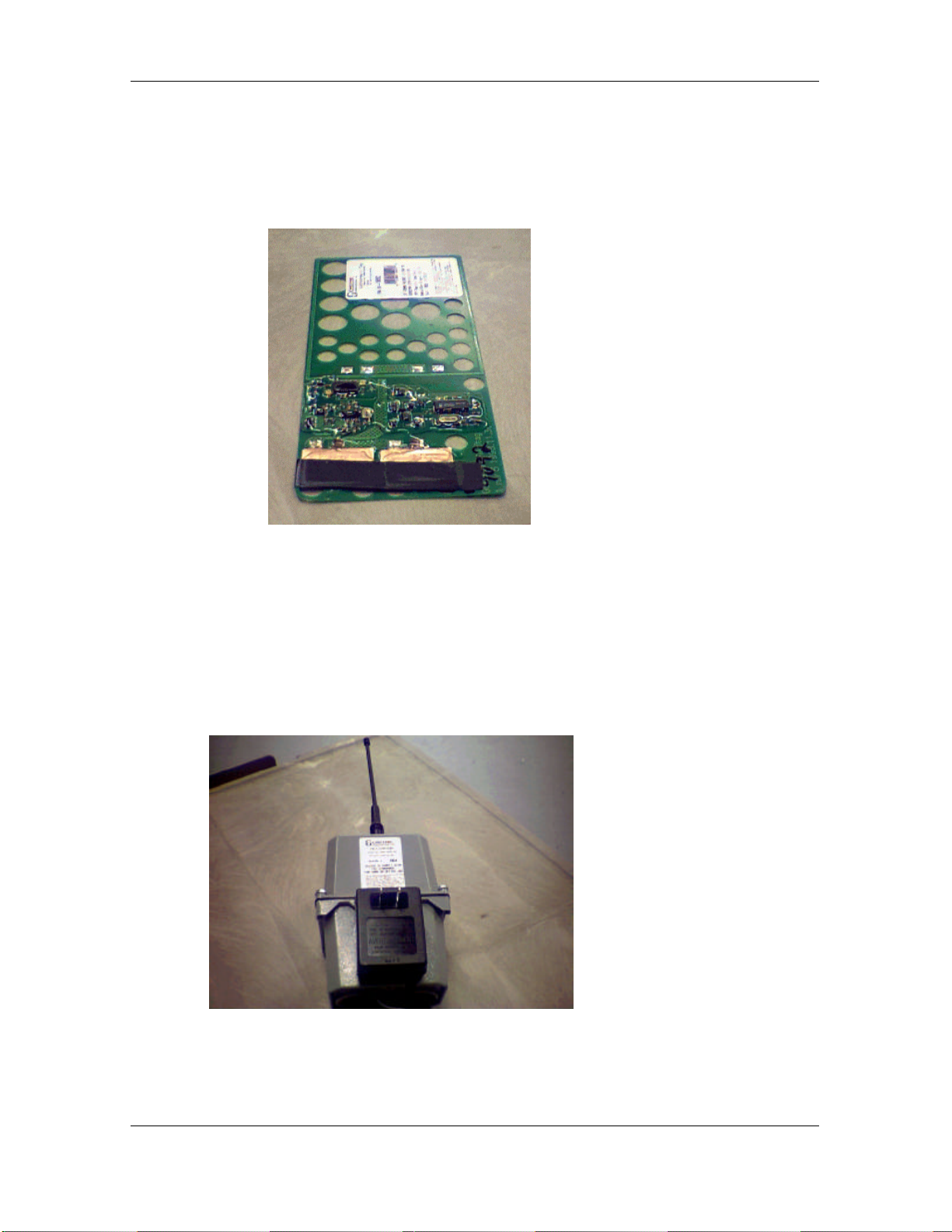
The following illustrations show where on the equipment the labels are to
be attached:
The Tag notice
label is affixed on
the perforated
section of the
circuit board on
the side of the
electronic
components
The Activator
notice label is
located on the
embossed
section of the
upper case,
above the AC/DC
transformer.
Revision 0 11-May-00 Page 7
 Loading...