

Page 1

ULS-100/10
Ultrasonic Liquid Level Switches
Instruction Bulletin No. 146077
General Description
The ULS-100/10 Series Liquid Level Detection System is an ideal, low cost, ultrasonic liquid
level detection system for many applications. It operates in a broad spectrum of viscous to
light liquids.
Principle of Operation
The ULS-100/10 Series operates using ultrasonic sound wave propagation. Ultrasonic sound
waves are greatly attenuated when transmitted through air. Conversely, when liquid is
present, transmission of the sound waves is greatly enhanced. The electronic control unit
generates electrical signals that are converted to bursts of ultrasonic energy at the sensor. The
ultrasonic bursts are transmitted across the liquid sensing gap. Upon receipt of a valid signal,
the solid-state electronics generate a data enable condition, indicating liquid is present. This
signal energizes a relay to provide a contact closure or a 4 mA/20 mA, 2-wire current output.
GEMS
Model No.
ULS-100
ULS-10
1. Standard sensor for contact type point level: 316 stainless steel.
2. Different sensor materials include Monel, Hastalloy, Titanium, Teflon,
Kynar, CPVC, PVC or any special metal, alloy. Consult Factory.
Mounting
Type
Integral
Remote
Integral
Remote
Model Description
Input Power
115 VAC/230 VAC
24 VDC/12 VDC
115 VAC/230 VAC
24 VDC
Notes:
Output
10 Amp DPDT
" "
10 Amp DPDT
2-wire 4/20mA
Function
Standard Point
Level
Standard Point
Level
3. 3/4" NPT is standard, different NPT and flanges are optional.
4. Standard length of sensor is 1". Extension up to 120" is available.
Page 2

Installation
General
The unit is easy to install. The sensor, with its integral electronics control unit, can be mounted
in any position or orientation desired. Remote-mounted electronics are also possible.
Make sure that all wiring, conduit and electrical fittings conform to local Electrical Codes for
the location selected.
Visual Inspection
Unpack the control unit and sensor assemblies. Visually inspect them for any damage. Advise Factory immediately if either assembly is damaged.
Preliminary Operational Check
Before installing the unit, a simple operational check-out should be performed:
1. Fill a container with liquid.
WARNING: In a hazardous environment, never open housing cover or connect
power leads without first disconnecting electrical power at the source.
2. Open the control unit housing cover and connect power to the control unit. (See Wiring
Diagram - Page 5.)
3. Apply power from the source.
4. Place the sensor in the liquid. Relay should energize. If current source, current will
change from 4 mA (dry) to 20 mA (wet).
5. Remove sensor from the liquid. Relay will deenergize. System is functioning properly.
6. Disconnect power to the control unit.
7. Proceed to final installation.
If the system does not function, notify the Factory immediately.
- 2 -
Page 3
Final Installation
Invasive Contact Type
Follow the instructions below:
1. Drill a suitable hole in the vessel or pipe wall and tap for 3/4" NPT. In thin walled
vessel or material not suitable for threading, weld or braze a bushing to accept the
sensor.
2. Screw the sensor in the threaded section and make sure that there is a good seal. Use a
pipe compound or sealing tape to avoid excessive tightening. Do not overtighten.
3. Run the power and control wiring cables to the electronics control unit.
Observe all applicable electrical codes and proper wiring procedures.
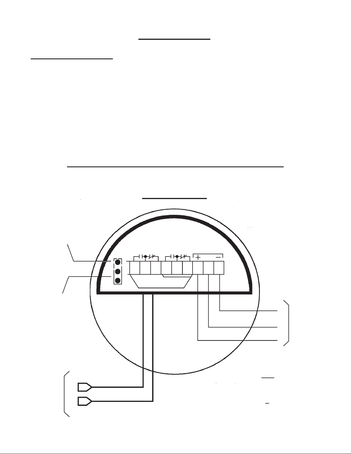
Wiring Diagram
Model ULS-100
Jumper
High Level
Fail Safe
Jumper
Normal
Position
Coaxial
Cable To
Sensor
J1
J2
CNCNOCNCL1
NO
DPDT
SPDT
POWER
L2 G
115 AC
50/60 HZ
Note
24V DC or 12V DC
Connect Positive (+) to L1 - Terminal
Connect GND ( ) to G - Terminal
- 3 -
Page 4

Wiring Diagram
Model ULS-10
Coaxial
Cable To
Sensor
Note
- Two-Wire Unit
- 4-20mA Output
9V DC to
42V DC
}
- 4 -
Page 5

Specifications and Dimensions
(ULS-10 and ULS-100 Models)
Model ULS-10
Repeatability - 2mm Typical
Delay (On) - 0.5 Seconds (Standard)
Input Power - 115 VAC, 230 VAC, 50/60 Hz AC (Standard)
12 VDC & 24 VDC optional
Outputs - 10A DPDT Relay (Standard)
Two-Wire (4mA - Dry, 20mA - Wet)
Housing - Cast aluminum
Nema Ratings - 4 and 7; Watertight and Explosionproof;
Class I, Group C & D; Class II, Group E, F & G; and
Class III, Division 1 & 2
Sensor Materials - 316 Stainless Steel (Standard)
Sensor Mounting - 3/4" NPT (Standard)
(Flanges mounting available)
Temperature Ratings
Sensor: -40°F to 300°F
Electronics: -20°F to 170°F
Pressure Rating - Up to 1000 psig
Weight - 1 Lb. Approx.
1/4"
4"
L1 =
3-3/4"
3/4" NPT
Threaded Hub
3/4" NPT
Thread
2-1/2"
7/8"
Model ULS-100
Repeatability - 1mm Typical
Accuracy - 0.5 Seconds, Other options available
Input Power - 115 VAC, 230 VAC, 50/60 Hz
12 VDC & 24 VDC optional
Output - 10A DPDT
Integral Housing - Cast aluminum; remote housing
optional
Nema Ratings - 4 and 7; Watertight and Explosionproof;
Class I, Group C & D; Class II, Group E, F & G; and
Class III, Division 1 & 2
Sensor Materials - 316 Stainless Steel; Other metals,
Teflon and Kynar are optional
Sensor Mounting - 3/4" (19mm)Std;
(Flanges and other sizes optional)
Temperature Ratings
Sensor: -40°F to 300°F (-40°C to 149°C)
Electronics: -20°F to 170°F (-29°C to 77°C)
Pressure Rating - Up to 1000 psig (68 bar)
Plastics: Up to 100 psig (6.8 bar)
Weight - 1 Lb (0.45kg) Approx.
4"
A
1-1/2"
3-3/4"
3/4" NPT
Flange
Optional
7/8"
- 5 -
Page 6

Intrinsically Safe Installation
(Model ULS-10)
Hazardous Location
Class I, II, III, Division 1
Groups A, B, C, D, E, G
Entity Parameters:
Vmax = 36 VDC
Imax = 150 mA
Ci = 0 uF
Li = 54 uH
+
-
Non-Hazardous Location
Associated
Equipment
Ca, La, Vac, Isc
(See Note 2)
Vmax
Control
Equipment
Cable
Barriers
Safe Ground
F.M.R.C. Approved Barriers
Notes
1. Control equipment must not use or generate
more than 250V.
2. Vmax
Ca
La
³ Vac, Imax ³ Isc
³ Ccable + Ci
³ Lcable + Li
- 6 -
Page 7

Maintenance
Electronics are constructed with solid-state components and epoxy-potted. Periodically, check
and clean the sensor when used with liquids which cause a coating build-up on the sensor. No
other maintenance is required.
Cleaning
If the pipe or vessel to which the unit is mounted is to be steam-cleaned or cleaned with abrasive detergents, remove the entire unit before cleaning by:
(1) Disconnecting the power at source;
(2) Opening the housing cover;
(3) Removing power and control wiring cables;
(4) Unthreading the sensor.
To reinstall, follow installation procedures.
System Malfunction
Should the system malfunction, notify the Factory immediately.
- 7 -
Page 8

Warranty
All components of GEMS systems are warranted to be free from defects in material and workmanship for a period of one year from the date of shipment to the original purchaser. This warranty
applies to general purchaser and to components installed, serviced and operated according to
GEMS' instruction manual.
GEMS will repair or replace, at its option, FOB at its plant or any other location designated, any
part which proves to be defective in manufacture or workmanship.
All claims must be made within the Warranty period. No claims outside of the Warranty period
will be honored.
Warranties are not applied to any components which have been damaged by improper installation,
use exposure to unusual atmospheric conditions or components which have been misused, abused,
damaged by neglect or accident. This warranty shall not apply to any components which have been
altered or repaired without the prior written consent of GEMS.
GEMS assumes no responsibility or liability for any labor or material or back charges, without
written authorization. Any products returned must be with prior written authorization.
THE FOREGOING IS IN LIEU OF ALL OTHER WARRANTIES, EXPRESS OR IMPLIED, INCLUDING ANY
WARRANTIES OF MERCHANTABILITY AND/OR FOR FITNESS FOR PARTICULAR PURPOSE AND GEMS
ASSUMES NO OTHER LIABILITIES EXPRESS OR IMPLIED. GEMS SHALL NOT BE LIABLE FOR NORMAL
WEAR AND TEAR, NOR FOR DIRECT, INCIDENTAL OR CONSEQUENTIAL DAMAGES. IN NO EVENT SHALL
GEMS LIABILITY EXCEED THE PRICE OF ITS PRODUCT AT THE TIME OF PURCHASE.
Important Points!
Product must be maintained and installed in strict accordance with
the National Electrical Code and GEMS product catalog and
instruction bulletin. Failure to observe this warning could result in
serious injuries or damages.
An appropriate explosion-proof enclosure or intrinsically safe
interface device must be used for hazardous area applications
involving such things as (but not limited to) ignitable mixtures,
combustible dust and flammable materials.
Pressure and temperature limitations shown on individual catalog
pages and drawings for the specified level switches must not be
exceeded. These pressures and temperatures take into consideration possible system surge pressures/temperatures and their
frequencies.
Life expectancy of switch contacts varies with applications.
Contact GEMS if life cycle testing is required.
Ambient temperature changes do affect switch set points, since
the specific gravity of a liquid can vary with temperature.
Level switches have been designed to resist shock and vibration;
however, shock and vibration should be minimized.
Liquid media containing particulate and/or debris should be
filtered to ensure proper operation of GEMS products.
Electrical entries and mounting points may require liquid/vapor
sealing if located in an enclosed tank.
Selection of materials for compatibility with the media is critical to
the life and operation of GEMS level switches. Take care in the
proper selection of materials of construction; particularly wetted
materials.
P/N 146077
Rev. H
Level switches must not be field repaired.
Physical damaged sustained by the product may render it
unserviceable.
Gems Sensors Inc.
One Cowles Road
Plainville, CT 06062-1198
tel: 860-747-3000
fax: 860-747-4244
www,gemssensors.com
 Loading...