

Page 1
(100 mm)
Flow Set Point Switching – RFS Types
Combines visual confirmation of flow
with dynamic, electronic switch operation
Easy, adjustable switch point calibration:
a local LED signals when set point is reached
RotorFlow® Switches build an extra level of reliability and
protection into your equipment. By principle of operation,
the rotor cannot be deceived into indicating a positive
flow situation when no flow actually exists. Once
set to a desired actuation point, RotorFlow
will switch to a “no-flow” condition should
the rotor stop for any reason.
Typical Applications
Protect expensive electronic
equipment from coolant flow
failure on...
• Semiconductor
Processing Equipment
• Lasers • Medical Equipment
• X-Ray and Other High Power Tubes
• Robotic Welding Equipment
File No. E45168
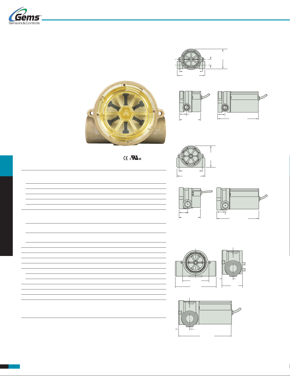
Dimensions
Polypropylene Bodies
2.37˝
(60.2 mm)
.64˝ (16.3 mm)
2.50˝ (63.5 mm)
3.06˝ (77.7 mm)
VDC VAC
.80˝
(20.3 mm)
2.38˝ (60.5 mm)
Brass and Stainless Steel Bodies - .25˝ and .50˝ Port
2.37˝
(60.2 mm)
.80˝ (20.3 mm)
4.50˝ (114.3 mm)
FLOW SENSORS – ELECTRONIC
Specifications
Wetted Materials
Body Brass, 316 Stainless Steel or Polypropylene
(Hydrolytically Stable, Glass Reinforced)
Rotor Pin Ceramic
Rotor PPS Composite, Black
Lens Polysulfone
O-Ring Viton® (Alloy Bodies); Buna N (Polypropylene Body)
Low Flow Adaptor Glass Reinforced Polypropylene
Operating Pressure, Maximum
Brass or Stainless Steel Body 200 PSIG (13.8 bar) @ 70°F (21°C),
100 PSIG (6.9 bar) Max. @ 212°F (100°C)
Polypropylene Body 100 PSIG (6.9 bar) @ 70°F (21°C),
40 PSI (2.8 bar) Max. @ 180°F (82°C)
Operating Temperature,
Brass or Stainless Steel Body -20°F to 212°F (-29°C to 100°C)
Polypropylene Body -20°F to 180°F (-29°C to 82°C)
Electronics 150°F (65°C) Ambient
Viscosity, Maximum 200 SSU
Input Power 24 VDC or 115 VAC
Relay Contact Ratings (SPDT) 1 Amp, 24 VDC Resistive; 0.3 Amp, 110 VAC
Current Consumption No Load Load (Relay Energized)
24 VDC 20mA 35mA
115 VAC 45mA 95mA
Repeatability 2% Maximum Deviation
Set Point Accuracy (Factory Set) ± 5%
Set Point Differential 15% Maximum
Electrical Termination 20 AWG PVC-Jacketed, 24˝ Cable. Color Codes:
Red = +VAC/VDC, Black = Ground,
White = N.O. Contact, Brown = N.C. Contact,
Green = Common
Note:
1. Optional pulsed output available with RFS. Consult factory.
1
2.50˝ (63.5 mm)
3.01˝ (76.4 mm)
VDC VAC
.87˝
(22.1 mm)
2.32˝ (58.9 mm)
1/4˝ PORTS = .80˝ (20.3 mm)
1/2˝ PORTS = .87˝ (22.1 mm)
4.50˝ (114.3 mm)
Brass and Stainless Steel Bodies - .75˝ and 1.00˝ Port
VDC
2.50˝
(63.5 mm)
3.94˝
1.06˝
(26.9 mm)
2˝
(50.8 mm)
VAC
1.06˝
(26.9 mm)
4.76˝
(120.9 mm)
F -2
Visit www.GemsSensors.com for most current information.
RFS Type / p1of2 / 30-JUL-14
Page 2

1/2" STRAIN
12
PSI PSI
110
RFS TYPE
Switch Set Point Calibration With LED Signal (RFS Type)
With the unit installed in the line and power supplied, complete the following steps to
calibrate switch actuation point with proper flow rate. A small flat-blade screwdriver is
the only tool required.
1. Adjust liquid flow in the line to the rate at which switch actuation is desired.
ILLUMINATED WHEN
CLOSED. AIDS FIELD
2. Insert screwdriver into opening on backside of housing and fit blade into the
potentiometer adjustment screw inside.
3. If LED is not illuminated, slowly turn screwdriver counterclockwise and stop as
soon as LED illuminates.
4. If LED is illuminated, turn screwdriver clockwise until LED light goes out. Then,
slowly turn screwdriver counterclockwise and stop as soon as LED illuminates.
How To Order
Specify Part Number based on desired body material, port size and input power rating.
Material
Body
Port Size
Polypropylene
115 VAC 155876
115 VAC 155886
115 VAC 156266
Brass
115 VAC 156269
115 VAC 180396
115 VAC 181689
9/16-18** 0.1 to 1.0 0.5 to 5.0
115 VAC 165074
Stainless 24 VDC 165077
Steel
24 VDC 181691
24 VDC 181693
* With use of Low Flow Adapter supplied. See Page F-8 for more information.
** Straight thread with O-ring seal.
– Stock Items.
Special Requirements:
GEMS caters to OEM needs with special configurations for potable water and
enhanced chemical capabilities. Consult factory for further details.
For higher pressure/temperature ratings, stainless face plates are available.
Consult factory.
Flow Ranges – GPM
NPT
Low Range* Standard Range
.25˝ 0.1 to 1.0 0.5 to 5.0
.50˝ 1.5 to 12.0 4.0 to 20.0
.25˝ 0.1 to 1.0 0.5 to 5.0
.50˝ 1.5 to 12.0 4.0 to 20.0
.75˝ – 5.0 to 30.0
1.00˝ – 8.0 to 60.0
.50˝ 1.5 to 12.0 4.0 to 20.0
.75˝ – 5.0 to 30.0
1.00˝ – 8.0 to 60.0
Input
Power
Part
Number
24 VDC 155425
24 VDC 155485
24 VDC 156265
24 VDC 156268
24 VDC 180395
24 VDC 181688
24 VDC 165073
115 VAC 165078
115 VAC 181692
115 VAC 181694
High Resolution Black Rotor
PPS composite. Each of the six rotor
arms is magnetized. A PTFE loaded
bushing ensures long life.
Pressure Drop-Typical
Standard
Flow Range
Units
Low Flow
Range Units
High Flow
Units
LED INDICATOR IS
RELAY SWITCH IS
CALIBRATION
PSI
RELIEF HOLE
CABLE
OUTPUT
SET POINT
ADJUSTMENT
9
1/4˝
Ports
6
3
0
0 1 2 3 4 5 10 15 20 25
9
6
1/4˝ Ports
3
0
0
.1 .2 .3 .4 .5 .6 .7 .8 .91.0 2 3 4 5 10 15
12
9
3/4˝
6
Ports
3
0
0
10 20
30
1/2˝ Ports
Flow Rate – GPM
Flow Rate – GPM
506070
40
Flow Rate – GPM
1/2˝ Ports
1.0˝ Ports
80 90
FLOW SENSORS – ELECTRONIC
100
RFS Type / p2of2 / 30-JUL-14
Visit www.GemsSensors.com for most current information.
F-3
 Loading...