

Page 1
RFO/RFA-2500 Series Continuous Output
RotorFlow® Sensors
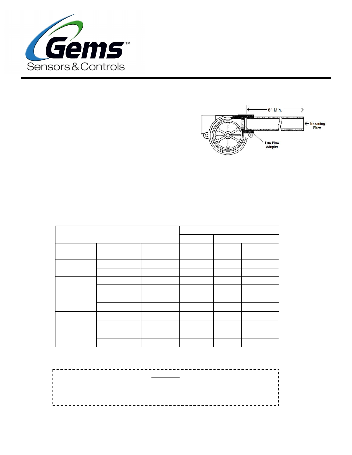
RotorFlow units monitor dynamic fluid flow. The rotor reacts to
turbulence, pulsation, entrained air, and other flow anomalies
induced in the flow stream by other process hardware. For
optimum performance, install RotorFlow units where nominal
flow conditions exist, with ports located at the top. Incoming
flow may be placed to either port. A minimum of 8" of straight
pipe on the inlet side is recommended.
(RFO) and voltage output (RFA) are determined by the velocity
of the monitored fluid acting on the sensor rotor. Input piping
with an orifice smaller than that of the sensor input will affect
sensor output.
Note:
Frequency output
Instruction Bulletin No.
157258
Rev. J
Low Flow Applications
A low flow adapter is supplied with all RotorFlow units. It is used to produce accurate response at low flow
rates. Fit the adapter as shown above, in the port selected for incoming flow.
Body
Material
Polypropylene
Brass
Stainless
Steel
*Note: Other low flow ranges are available, Please consult the Factory.
9/16 - 18 J514
Port Size
NPT
.25"
.50"
.25"
.50"
.75"
1.0"
1/2" NPT
.75"
1.0"
Part Number
RFO
155421
155481
156261
156262
194761
194762
165071
165075
194763
194764
Flow Range - GPM
Standard
High
0.5 - 5.0 0.1 - 1.0 152147
4.0 - 20.0 1.5 - 12.0 151832
0.5 - 5.0 0.1 - 1.0 152147
4.0 - 20.0 1.5 - 12.0 151832
5.0 - 30.0
8.0 - 60.0
0.5 - 5.0 0.1 - 1.0 152147
4.0 - 20.0 1.5 - 12
5.0 - 30.0
8.0 - 60.0
Range
See Flow Range Chart below.
Low*
Range
N/A
N/A
N/A
N/A
Low Flow
Adapter
Part Number
N/A
N/A
151832
N/A
N/A
WARNING
When determining chemical compatibility of materials of construction, the flow media
and application-associated environmental conditions should be carefully considered
Page 2
Installation
RotorFlow Sensors connect to piping via NPT mating thread forms. The following guidelines are provided to assist
with installation for a leak-free seal, without damage to the unit.
1) Apply pipe thread sealant to male pipe threads.
2) Thread RotorFlow unit onto male pipe thread until hand-tight.
3) Tighten pipe 1 to 1-1/2 additional turns.
4) If improper seal results, continue turning pipe into unit in 1/4 turn increments.
Do not exceed one additional turn on plastic versions.
Recommended pipe Sealants: (a) Permatex® “No More Leaks” (b) Teflon® Thread Tape.
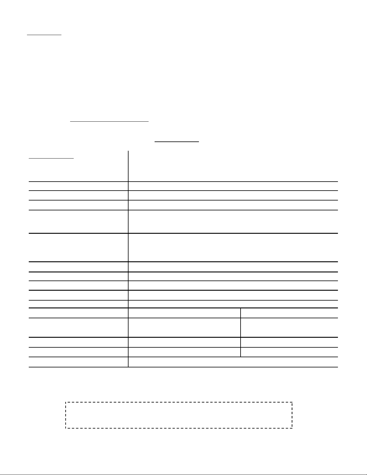
Specifications
Wetted Materials
Operating Pressure, Max.
Brass/Stainless Steel Body
Polypropylene Body
Operating Temperature, Max.
Electronics (All Bodies)
Viscosity, Max. 200 SSU
Input Power RFO: 4.5 to 24 VDC/12mA RFA: 24 VDC (±10%)/22mA
Output Signal
Body
Rotor Pin
Rotor
Lens
O-Ring
Brass Body 212°F (100°C)
Stainless Steel Body 212°F (100°C)
Polypropylene Body 180°F (82.2°C)
RFO: Frequency Pulses Proportional to Flow Rate
Stainless Steel, Brass or Polypropylene
(Hydrolytically Stable, Glass-Reinforced)†
Ceramic
PPS/Teflon Composite; Black
Polysulfone
Buna N or Viton
200 PSIG at 70°F/80 PSIG @ 212°F
100 PSIG at 70°F/40 PSIG @ 212°F
150°F (65.5°C) - Ambient
RFA: 0 - 10 VDC.
Proportional to Flow Rate
Current Source Output, Max. RFO: 70mA (Max) RFA: 10mA (Max)
Frequency Output Range RFO: ~15 Hz to 225 Hz
Electrical Termination Red (+) VDC, Black (-) Ground, White - Signal Output
†
Hydrolytically Stable, glass-reinforced, Polypropylene is
UL-recognized to UL746B at a relative temperature index of 65°C
A RotorFlow Repair Kit is available, including the following replacement parts:
lens, O-ring, shaft, and rotor. Consult Factory to order.
Page 3

This product is suitable for Class I and Class II applications only, per the requirements of standard EN60730 and any additional specific
requirements for a particular application or medium being sensed. Class I compliance of metal bodied units requires a ground connection
between the metal body and the earthing system of the installation. Class I compliance of plastic bodied units in contact with a conductive
medium requires that the medium be effectively earthed so as to provide an earthed barrier between the unit and accessible areas. For Class
III compliance, a supply at safety extra-low voltage (SELV) must be provided. Please consult the Factory for compliance information on
specific part numbers.
Filtration and Cleaning:
RotorFlow sensor, accumulation is easily cleared by removing the lens from the body. The lens is removed by turning
its center rib 45° counter-clockwise and then pulling it out. To reinstall the lens, simply reverse the process. Pressure
must be relieved from the system prior to sensor clean-out.
150 micron filtration is recommended. However, should foreign particles enter the
Signal Output (RFO):
in an on/off pulse of the DC voltage supplied to the unit.
It is compatible with all digital logic families. Input
voltage range is 4.5 to 24 VDC. Frequency of the output
pulse is proportional to the flow rate and ranges from
approximately 15 Hz at low flow to 225 Hz at high flow.
See example below:
Low Flow
Output signal for RFO types
Electrical Data:
connected via a multi-conductor, PVC-jacketed
24” cable. Color codes are shown below:
RFO: 4.5 VDC to 24 VDC (Max)
RFA: 24 VDC ± 10%
+ VDC Red
Ground Black
Signal Output White
Input power and output are
High Flow
Signal Output (RFA)
Note: Consult Factory for flow
rate/frequency curves.
Output signal for RFA types is a voltage
output from 0-10 VDC and is proportional
to the flow rate.
Panel Mounting
Any RotorFlow sensor may be panel mounted using holes integrated into the bodies:
Plastic (Polypropylene) Bodies
self-tapping screws.
replaced with standard machine screws if reinstallation should be required.
Note:
: Two (2) mounting ears are provided at the body centerline to receive #8
ANSI T Type 23 self-tapping screws are recommended. They may be
Page 4

Brass and Stainless Steel Bodies:
Two (2) mounting holes are provided on the body centerline, as shown
below.#8-32 UNC - 2B screws are required for mounting.
Plastic. Brass, Stainless Steel
1/4”, 1/2”, 9/16”-18
Important Points!
Product must be maintained and installed in
strict accordance with the National Electrical
Code and Gems product catalog and instruction
bulletin. Failure to observe this warning could
result in serious injuries or damages.
The pressure and temperature limitations
shown on the individual catalog pages and
drawings for the specified flow swit c hes mu s t
not be excee d e d. T h ese p r essures an d
temperatures take into consideration possible
system surge pressures/temperatures and
their frequencies.
Selection of materials for compatibility with the
media is critical to the life and operation of
GEMS flow switches. Take care in the proper
selection of materials of construction,
particularly wetted materials.
Life expectancy of switch contacts varies with
applications. Contact GEMS if life cycle testing
is required.
Brass/Stainless Steel
3/4” & 1”
Ambi ent temperature changes do affect switch
set points, since the specific gravity of a liquid can
vary with temperature.
Flow switches have been designed to resist shock and
vibration; however, shock and vibration should be
minimized.
Filter liquid media containing particulate and/or
debris to ensure the proper operation of our
products.
Electrical entries and mounting points in an
enclosed tank may require liquid/vapor sealing.
Flow switches must not be field-repaired.
Physical damage sustained by the product may
render it unserviceable.
Gems Sensors & Controls
Telephone: 1-800-378-1600 | Email: info@gemssensors.com | www.GemsSensors.com
| One Cowles Road | Plainville, CT 06062-1198
 Loading...