

Page 1
Model LS-750
Steel Tank Sensor
Instruction Bulletin No. 157728
Environmental Products
These Sensors may not be compatible with indicating
and alarm equipment supplied by other manufacturers
Note: LS-750 sensors are non-voltage producing devices and do not contain energy storing
components. However, since primary use is in hazardous locations, an appropriate intrinsically safe interface device is required.
With its compact size, the Gems LS-750 single float, liquid level sensor is ideally suited for use in steel doublewall tanks. It requires no calibration, and is easy to install and maintain. When positioned vertically at the bottom
of a steel tank’s stand pipe, it reliably senses the presence of a liquid. It detects hydrocarbons and water as low
as 3/4" from the bottom of a tank or sump. The LS-750 sensor features an epoxy-encapsulated design providing
an environmental seal, that makes it a fine choice for harsh environments. An integral slosh shield guards the
float from debris; thereby assuring dependable service.
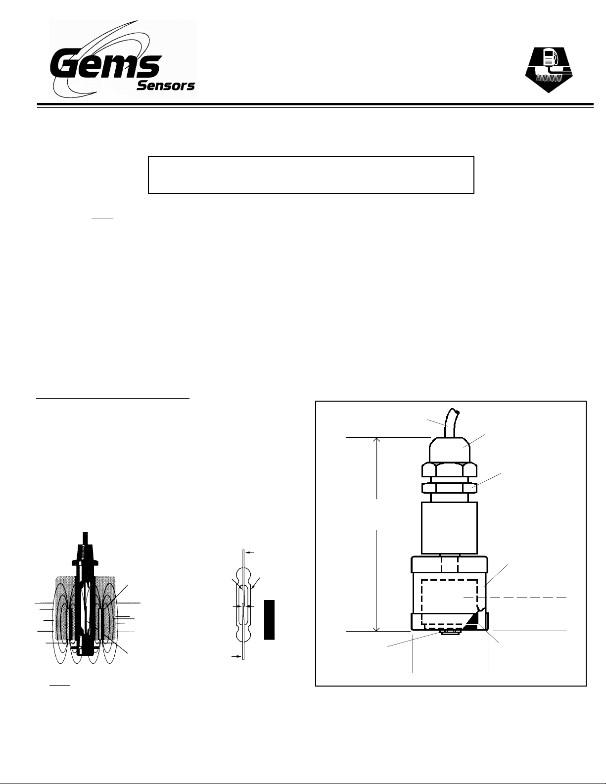
Sensor Operating Principle
Gems LS-750 liquid level sensor operates on a direct, simple
principle. A float is equipped with powerful, permanent magnets. As the float rises or lowers with liquid level, it actuates a
magnetic reed switch mounted within the stem. This condition either opens or closes the electrical circuit to operate an
external alarm or control circuit. When mounted vertically,
this basic design provides a consistent accuracy
of ±1/8th inch.
N
Permanent
Magnet
Float
Hermetically
Sealed Magnetic
Reed Switch
Reed
Switch
N
Envelope
S
S
Glass
S
MAGNET
N
Dimensions
3-1/2" Ref.
(88.9 mm)
Retaining Ring
Cable
!
1-7/16" Ref.
(36.5 mm)
Sealing
Nut
Liquid-Tight
Fitting
Slosh
Shield
3/4" Actuation
(19.0 mm)
Float
!
!
!
Note: Please refer to specific Gems outline drawings for
operational specifications.
Page 2
Read all instructions before beginning - Follow all safety precautions
Barricade the area
Do not allow vehicles
or unauthorized people
in the work area
Do not smoke or allow
open flames in the
work area
WARNINGS
Read the instructions and warnings carefully before installing the sensor. This unit must be installed in accordance with National Electrical Code ANSI/NPFA-70, 1990; as well as Federal, State and local codes and any
other applicable safety codes.
1. To avoid electrical shock, which could kill you, be sure AC power to monitor is off during installation.
2. The nature of the sensor is that it is a non-voltage producing device, containing limited energy-storing
components. However, since its primary use is in a hazardous location, an appropriate intrinsically safe
interface device must be used.
Dangerous environment.
Failure to install this equipment in
accordance with NFPA 30A and
NFPA 70 could result in severe
injury or death.
Read, understand and follow
NFPA 30A and NFPA 70.
Note: Failure to observe these warnings could result in serious injury and
death, as well as undetected potential environmental and health hazards.
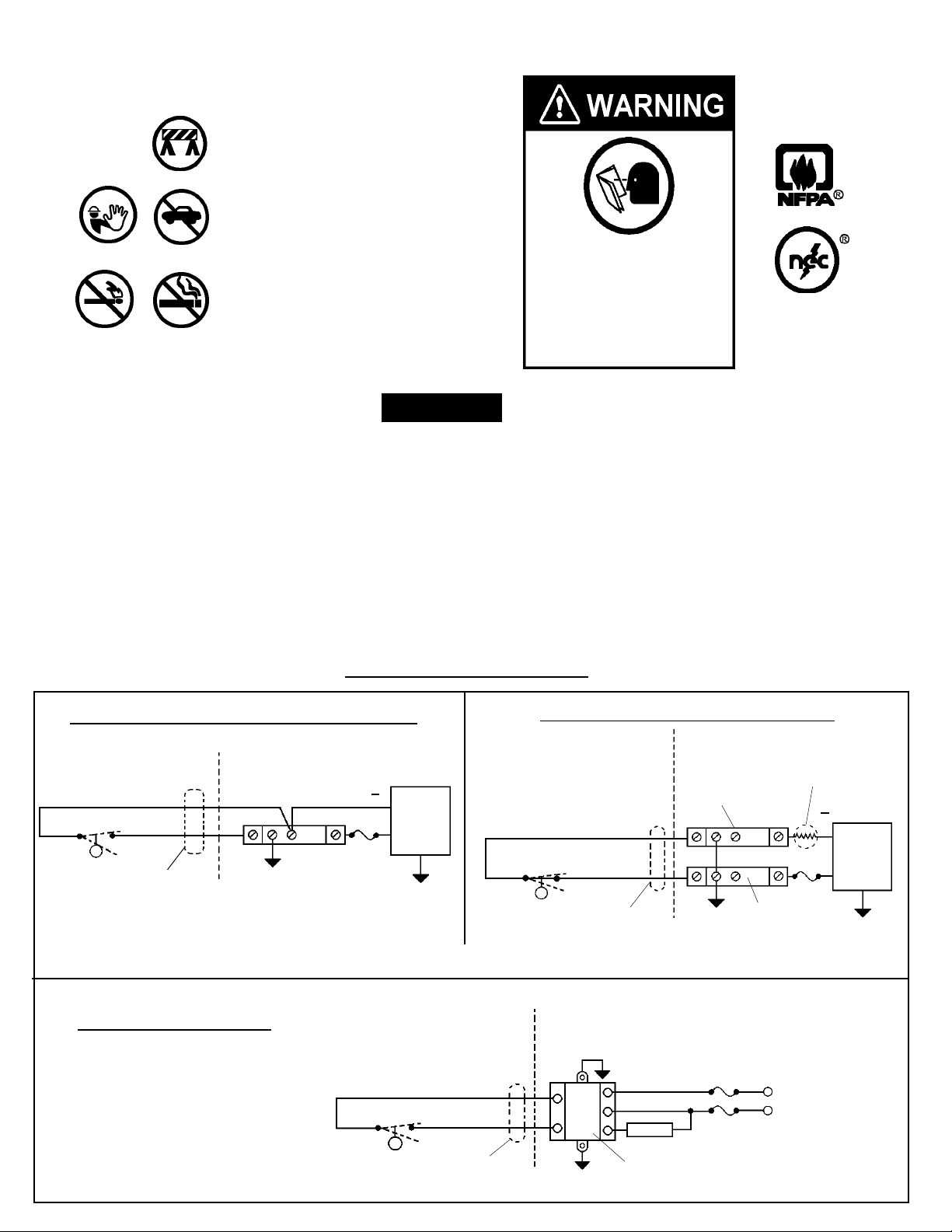
Typical Wiring Diagrams
Non-Isolated System – Single Zener Barrier
Hazardous
Area
Black
Red
N.O. Dry
or
N.C. Dry
2-Conductor
Cable
If two signal lines must be maintained at above ground potential, an individual zener barrier is required per single line.
Single Safe-Pak® Relay
Non-Hazard-
ous Area
3
21
Fuse
( )
(+)
DC
Power
Supply
Annunc.
N.O. Dry
N.C. Dry
Hazardous
Area
Safe-Pak® is an intrinsically
safe, solid-state relay.
N.O. Dry
or
N.C. Dry
Black
Red
2-Conductor
Cable
Isolated System – Dual Zener Barrier
Hazardous
Area
Black
Red
or
2-Conductor
Cable
Non-Hazard-
ous Area
Load
SAFE-PAK
Non-Hazard-
ous Area
Supply Barrier
3
2
3
2
Fuse
Fuse
1
1
Fuse
Signal
Return
Barrier
Hot VAC
Neutral VAC
Sense
Resistor
( )
Power
Supply
Annunc.
(+)
DC
Page 3

- IMPORTANT -
This manual assumes all preliminary site preparation is completed and that
field wiring from the monitor to the sensor junction box is in place.
Installation Instructions
A. Pre-installation Sensor Testing
1. Temporarily connect the two-wire sensor cable to the field wires in the sensor junction box. Turn Power on.
3. Turn the LS-750 upside down. Audible and visual indicators should alarm.
4. To remove alarm condition, turn the sensor right side up.
5. Secure the riser cap to the riser pipe.
6. Feed the sensor cable through the cord grip on the junction box.
7. Tighten the cable bushing nuts on the riser cap and junction box to ensure a watertight seal at the cable entry.
8. Using wire nuts, connect the two-wire sensor cable to the field wires in the sensor junction box.
B. Sensor Installation Instructions
1. Turn off power to the control. Note: Do not install the sensor if any liquid is present in the annular space.
Failure to comply will lead to an alarm.
2. Make sure no liquid is present in the annular space.
3. To be sure the sensor will reach the bottom of the annular space, first measure the sensor riser pipe from the
bottom of the pipe to the top. Then measure the same distance up the leader cable from its connection to the
sensing element and mark the leader cable.
4. Lower the float switch assembly into the
riser pipe until the float switch touches the
bottom of the tank.
5. Keeping the cable taut, secure the
sensor assembly in place by attaching the
grip cord.
Note: The float switch assembly should
not hang by the cable, but should rest
lightly on the bottom of the tank
supported by the cable.
Typical Installation
Weatherproof
Junction Box
Epoxy Seal
Per NFPA Spec.
To Probe
Junction Box
1/2" - 2" Dia.
Reducer
This product is suitable for Class I and Class
II applications only, per the requirements of
standard EN60730 and any additional specific
requirements for a particular application or
medium being sensed. Class I compliance of
metal bodied units requires a ground connection between the metal body and the earthing
system of the installation. Class I compliance of plastic bodied units in contact with a
conductive medium requires that the medium be effectively earthed so as to provide
an earthed
barrier between the unit and accessible areas. For Class III compliance, a supply at
safety extra-low voltage (SELV) must be provided. Please consult the Factory for compliance
information on specific part numbers.
Cable
2" Dia. Riser
STEEL
T ANK
See inset
Note: The float switch assembly should not hang by the cable, but should
rest lightly on the bottom of the tank supported by the cable.
LS-750 Sensor
must reach
bottom of tank
View of sensor
at bottom of tank
Page 4

Maintenance
Note: Please consult your state E.P.A. office or appropriate regulatory
agency regarding periodic inspection of the sensor. There are no user
serviceable parts.
WARNING
Product must be maintained and installed in strict accordance with the
National Electrical Code and the applicable GEMS technical bulletin and
instruction bulletin. Failure to observe this warning could result in serious
injuries or damages.
Warranty
Gems’ standard warranty applies
P/N 157728
Rev. B
 Loading...