

Page 1
Turbine Flow Rate Sensor
FT-330 Series - TurboFlow®
Instruction Bulletin No. 227372
Operating and Installation Instructions
Prior to installation, confirm system versus sensor specifications and media compatibility of sensor.
The system needs to be filtered to 50 microns prior to the sensor, and pulses/water hammer effects
should be minimized to prevent unit damage. Observe arr ow on bottom of unit for correct inlet and ou tlet port. Sensor can be mounted in any horizontal, vertical, or skewed orientation. Correctly installed,
the sensor works maintenanc e-free.
Installation
3/8" NPT Units:
Apply a sparse amount of thread sealant (Permatex "No More Leaks"
Insure that sealant does not en ter into the turbine and bear ing internal area. Hand-tighten unit in place.
Turn an additional 1/4 turn to provide seal. If seal leaks, turn an additional 1/4 turn until leak stops.
Do not exceed one additional turn tota l.
Specifications
®) or Teflon® tape to male threads.
WETTED MATERIALS TURBINE-PA COMPOSITE WITH 316 SS AXLE BEARING- POM HOUSING- PPE & PS BLEND
OPERATING PRESSURE 200 PSIG
BURST PRESSURE 1000 PSIG
OPERATING TEMPERATURE -4 F TO 176 F (-20 C TO 80 C)
VISCOSITY 32-81 SSU (1.8- 16 CENTISTOKES)
INPUT POWER 5 TO 24 VDC @8mA
OUTPUT SINKING OPEN COLLECTOR @ 25mA MAXIMUM
ACCURACY 2% OF READING
REPEATABILITY 1/2 % OF READING
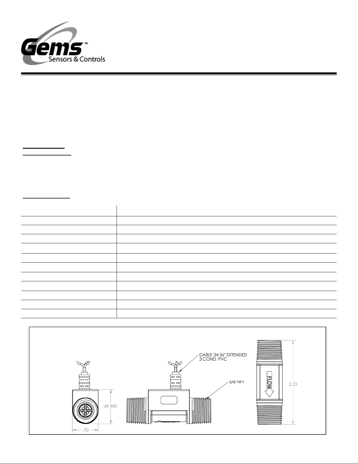
ELECTRICAL CONNECTIONS 3FT PVC JACKET 3 COND. CABLE
INLET/ OUTLET PORTS 3/8" NPT MALE
FILTER 50 MICRONS
Dimensions
Page 2
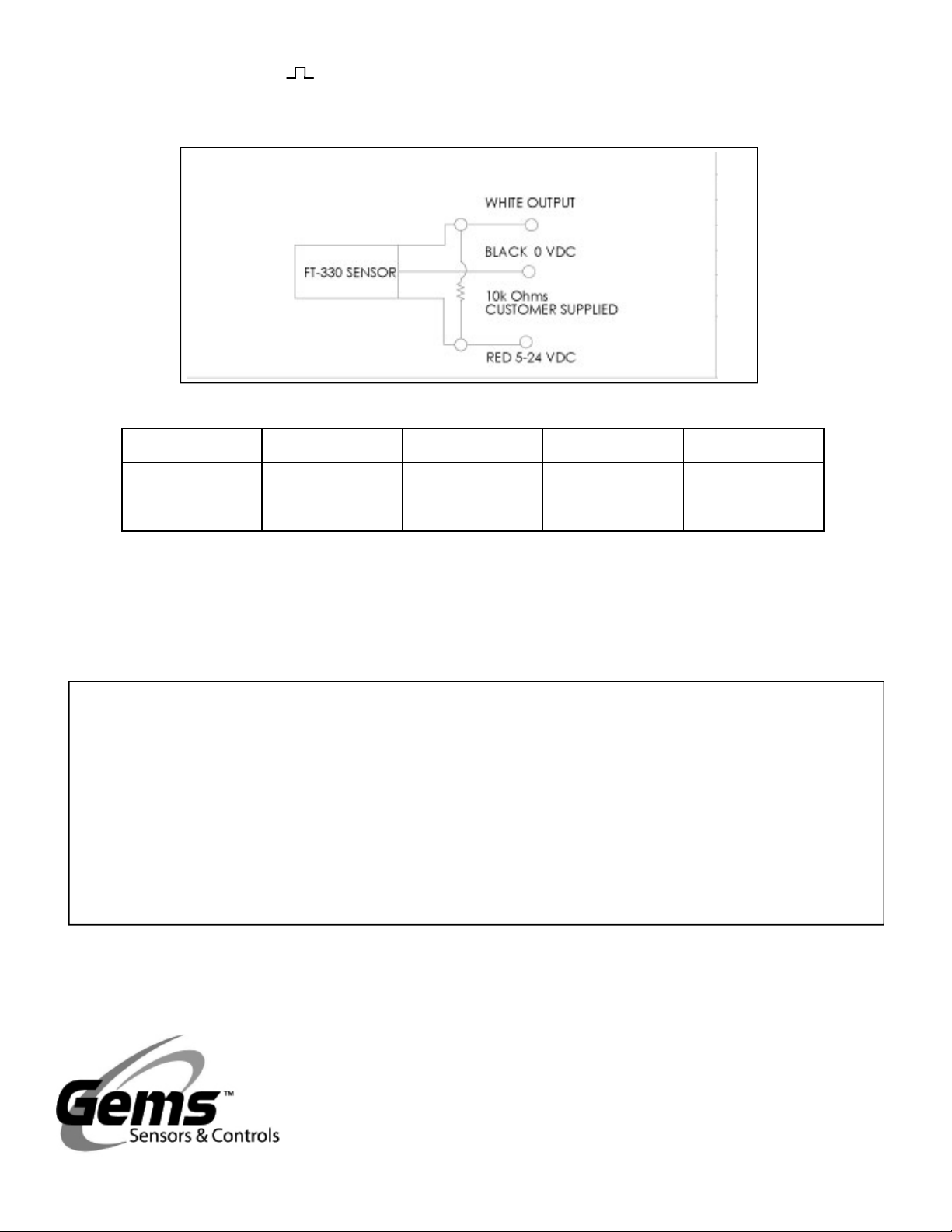
Electrical/Output Signal ( )
The output signal is a square wave signal, whose frequency varies linearly with flow rate. An external pull-up resistor
(user supplied) is required to insure that the open collector will sink less than 50 mA.
Wiring Diagram
P/N Thread Flow Range Pulses/GAL. Frequency (Hz)
226000 3/8 NPT 0.2-2 GPM 10200 34-343
226100 3/8 NPT 0.4-4 GPM ———- 28-340
The product is designed and manufactured in accordance with Sound Engineering Practice as defined by the Pressure
Equipment Directive 97/23/EC. This product must not be used as a “safety accessory” as defined by the Pressure Equipment Directive, Article 1, Paragraph 2.1.3. The presence of a CE Mark on the unit does not relate to the Pressure Equipment Directive.
Important Points!
Product must be maintained and installed in strict accordance with the National Electrical Code and GEMS technical brochure and instruction bulletin. Failure to observe
this warning could result in serious injuries or damages.
Pressure and temperature limitations shown on individual
catalog pages and drawings for the specified flow sensors
must not be exceeded.
Selection of materials for compatibility with the media is
critical to the life and operation of GEMS flow sensors.
Take care in the proper selection of materials of construc-
tion; particularly wetted materials.
Flow sensors have been designed to resist shock and
vibration; however, shock and vibration should be minimized.
Liquid media containing particulate and/or debris should
be filtered to ensure proper operation of GEMS products.
Flow sensors must not be field repaired.
Physical damage sustained by the product may render
it unserviceable.
Gems Sensors & Controls
One Cowles Road
Plainville, CT 06062
U.S.A.
Tel: 860-747-3000
Fax: 860.747.4244
Www.GemsSensors.com
Gems Sensors Ltd.
Lennox Road
Basingstoke
Hampshire RG22 4AW
U.K.
Tel. +44 (0) 1256.320244
Fax: +44 (0) 1256.473680
P/N 227372
Rev.
 Loading...