

Page 1

Piston-Type Flow Switches
Series FS-925/926 & FS-927/930
Instruction Bulletin No. 72949
Installation . . .
Unless otherwise specified at time of purchase, units are calibrated in a vertical position, with lead wires up.
Install unit in piping system, using standard pipe fitting procedures. Hold inlet fitting with wrench at installation
to prevent fitting torque accumulation. Be sure to keep thread sealing compound out of unit. Make sure that
flow is in proper direction - marked "IN" and "OUT" on housing. See wiring diagrams for electrical connections.
CAUTION: See "Switch Ratings" before connecting power.
Important Points!
Product must be maintained and installed in strict accordance with the National Electrical Code and Gems
product catalog and instruction bulletin. Failure to observe this warning could result in serious injuries or
damages.
An appropriate explosion-proof enclosure or intrinsically
safe interface device must be used for hazardous area
applications involving such things as (but not limited to)
ignitable mixtures, combustible dust and flammable materials.
*** Warning: To prevent ignition of flammable or combustible atmospheres, disconnect power before servicing.
Pressure and temperature limitations shown on individual
catalog pages and drawings for the specified flow switches
must not be exceeded. These pressures and temperatures take into consideration possible system surge pressures/temperatures and their frequencies.
Selection of materials for compatibility with the media is
critical to the life and operation of GEMS flow switches.
Take care in the proper selection of materials of construction; particularly wetted materials.
Life expectancy of switch contacts varies with applications. Contact GEMS if life cycle testing is required.
Ambient temperature changes do affect switch set
points, since the specific gravity of a liquid can vary with
temperature.
Flow switches have been designed to resist shock and
vibration; however, shock and vibration should be minimized.
Liquid media containing particulate and/or debris
should be filtered to ensure proper operation of GEMS
products.
Electrical entries and mounting points may require liquid/vapor sealing if located in an enclosed tank.
Flow switches must not be field repaired.
Physical damage sustained by the product may render it unserviceable.
CAUTION: Flow settings for FS-920 series switches are normally calibrated using water** @ +70°F on
increasing flow. If unit will be used to monitor liquids other than water, gas or air, Factory should have been
consulted at time of purchase for special calibration. All air/gas units are factory-calibrated using a special
piston. Water-calibrated units are not recommended for air/gas applications.
**
Note: Flow settings for FS-930 Viscosity Compensating type switches are calibrated in a vertical position
(lead wires up) with 300 SSU oil. Set points will be maintained within 20% of settings in a liquid viscosity
range of 40 to 2,000 SSU.
Specifications . . .
FS-925/FS-926 FS-930 FS-927
Wetted Materials
Housing
Piston
Brass Housing
Stainless Steel Housing
Spring
O-Ring
Other Wetted Parts
Pressure Rating
Operating
Proof
Burst
Operating Temperature
Brass or SS Piston
Polysulfone Piston
Repeatability
Set Point Accuracy
Set Point Differential
Switch*
Inlet/Outlet Ports
Electrical Termination
Brass or 316 SS
Polysulfone/Water - Brass/Oil or Air
316 SS
®
Viton
Epoxy
1000 PSIG
2500 PSIG
5000 PSIG
-20°F to +300°F
-20°F to +225°F
1% Maximum Deviation
±10%
15% Max.(FS-925) - 20% (FS-926)
SPDT, 20 VA
1/4" NPT
No. 18 AWG, 24" L., Polymeric Lead Wires
316 SS
Brass
Brass
15%, Max.
Brass
Brass
N/A
N/A
N/A
SS
1000 PSIG,Max.
-20°F to +200°F-20°F to +300°F
N/A
N/A
±15%
20% Max.
SPST, 20 VA
1/4" NPT
No. 18 AWG, 24" L.,
PVC Lead Wires
P/N 72949
Rev. P
Page 2
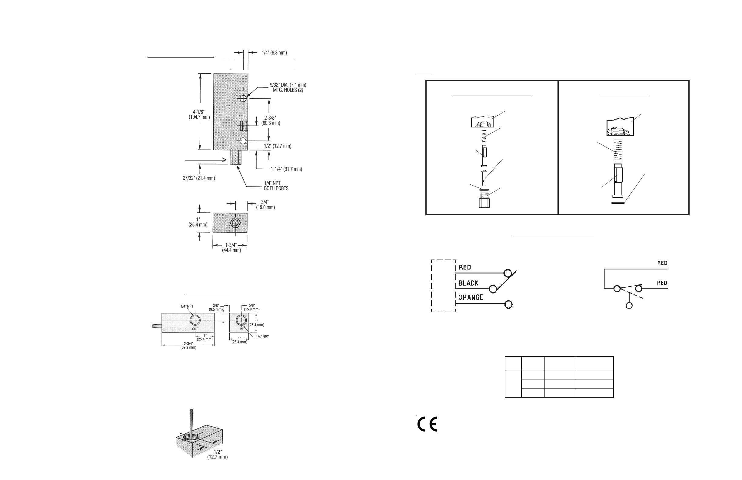
Dimensions . . .
FS-925/926/930 Series
Maintenance . . .
Accumulation of foreign debris should periodically be removed from these switches. Occasional "wipe-
down" cleaning when excessive contamination is present is all that is normally required. To clean: Remove
unit from system and disassemble as shown below. Clean all parts, reassemble and reinstall unit.
Note: 50 micron filtration is recommended.
For FS-926 the inlet fitting it torqued at the factory. Hold
fitting hex with wrench at installation to prevent additional
accumulation torque which could cause sensor malfunction.
(FS-925/FS-930)
(FS-926) 1-9/32" (32.5mm)
FS-925/926/930 Series
Housing
Spring
Piston
O-Ring
FS-925, FS-926, FS-930 Series
Low Flow Piston
(FS-926 ONLY)
Inlet
Fitting
Typical Wiring Diagrams
FS-927 Series
Housing
Spring
Retainer
Ring
Piston
FS-927 Series
FS-927 Series
Electrical Connection
(1/2" NPT Conduit)
A
C
B
Pin Connections for
Units with MS Receptacle
Switch Ratings
Max. Resistive Load
VA20Volts
0-30
120
240
This product is suitable for Class I and Class II applications only, per the requirements of standard EN60730 and any
additional specific requirements for a particular application or medium being sensed. Class I compliance of metal
bodied units requires a ground connection between the metal body and the earthing system of the installation. Class
I compliance of plastic bodied units in contact with a conductive medium requires that the medium be effectively
earthed so as to provide an earthed barrier between the unit and accessible areas. For Class III compliance, a supply
at safety extra-low voltage (SELV) must be provided. Please consult the Factory for compliance information on
specific part numbers.
Amps AC
.4
.17
.08
Amps DC
.3
.13
.06
 Loading...