

Page 1
G-11b ill
C
O
M
P
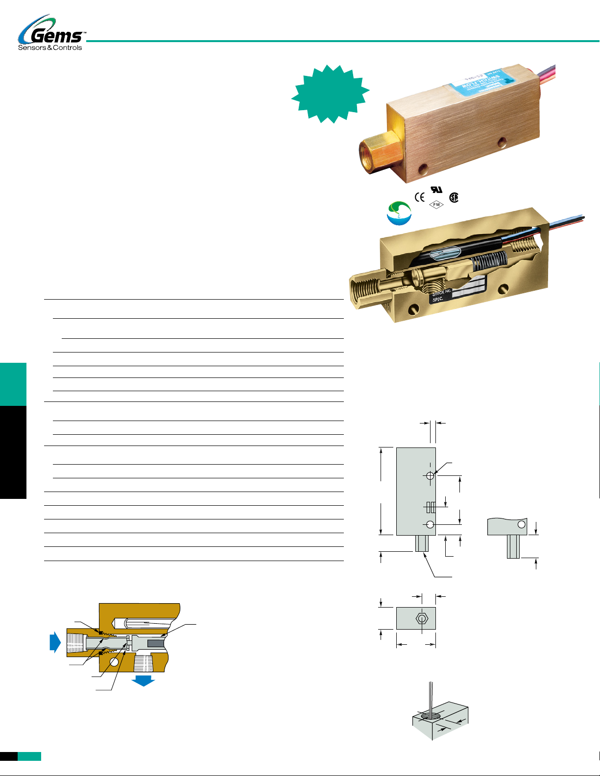
FS-925 Series – General Purpose
Flow Rate Settings: Liquids: 0.1 GPM to 1.5 GPM
Air/Gases: See Flow Settings at right
FS-926 Series – Low Flow
Port Size: 1/4˝ NPT
Primary Construction Material: Brass or Stainless Steel
Setting Type: Fixed
Flow Rate Settings: Liquids: 50-300 cc/min.
Air/Gases: See Flow Settings at right
UL Approved
Explosion-Proof
FS-925/926 Series
U.L. Recognized — File No. E31926
CSA Listed — File No. LR30200
FM Approved — File No. 1H3A2.AX
and 0A8A3AE
FLOW SWITCHES
These two series of precision-calibrated switches provides reliable and consistent
performance; repeatability is within 1%. FS-925 and FS-926 units are factory preset
for actuation at specified flow rates.
These switches provide accurate detection of excessive or insufficient flow rates
in such applications as: protecting against loss of fluid flow in hydraulic systems,
assuring proper coolant flow in semiconductor processing equipment, monitoring high
pressure lubrication systems, and ensuring proper air flow in water/waste systems.
Specifications
Wetted Materials
Housing Brass or 316 Stainless Steel
Piston
In Brass Housing Polysulfone for water; Brass for oil or air
Stainless Steel Housing 316 Stainless Steel
Low Flow Piston (FS-926) Same as Housing
Spring 316 Stainless Steel
O-Ring Viton
®
Other Wetted Parts Epoxy
Pressure Rating
Operating, Maximum 1000 PSIG (69 bar)
Proof 2500 PSIG (172 bar)
Burst 5000 PSIG (345 bar)
Operating Temperature
With Brass or S.S. Piston -20°F to +300°F (-29°C to +148.9°C)
With Polysulfone Piston -20°F to +225°F (-29°C to +107.2°C)
Repeatability 1% Maximum Deviation
Set Point Accuracy ±10%
Set Point Differential 15% Maximum
Switch* SPDT, 20 VA
Inlet/Outlet Ports 1/4˝ NPT
Electrical Termination No. 18 AWG, 24˝ L., Polymeric Lead Wires
*See “Electrical Data” on Page X-5 for more information.
Double Piston Detects Minute Flow – FS-926
An additional, lap-fitted
O-RING
BY-PASS
HOLES
METERING
ORIFICE
LOW-FLOW
PISTON
MAGNET CARRIER
PISTON
When metered bypass flow is exceeded, the resultant pressure differential displaces
the low-flow piston, moving the magnet carrier piston to actuate the reed switch.
Two large bypass holes in the piston skirt are exposed after actuation to maintain low
pressure drop.
piston is used in Gems
FS-926 Series to accurately
detect low-flow rates.
Calibration is determined
by one or more metering
holes in the end of the lowflow piston, which regulate
bypass flow, and therefore
the actuation setting.
R
o HS
®
G
T
E
M
N
A
S
I
L
Both the FS-925 and FS-926 use a spring-loaded
piston to detect positive flow with great precision. They
act upon direct fluid flow and will not show “falsepositive” flow indication as can happen with sensors
using indirect sensing methods such as pressure
measurement. The FS-926 incorporates an additional
lap-fitted piston for very low flows; see below.
Dimensions
4-1/8˝
(104.7 mm)
FS-925
27/32˝ (21.4 mm)
1˝
(25.4 mm)
1-3/4˝
(44.4 mm)
1/4˝ (6.3 mm)
9/32˝ DIA. (7.1 mm)
MTG. HOLES (2)
2-3/8˝
(60.3 mm)
1/2˝ (12.7 mm)
1-1/4˝ (31.7 mm)
1/4˝ NPT
BOTH PORTS
3/4˝
(19.0 mm)
FS-926
1 9/32˝ (32.6 mm)
Electrical Connection, 1/2˝ NPT Conduit
1/2"
(12.7 mm)
G-12
Visit www.GemsSensors.com for most current information.
FS-925/926 Series / p1of2 / 30-SEP-14
Page 2
2.0
PISTON TYPE
Flow Settings, Air (Typical)
Dependent on operating line pressure. Examples of set point ranges at a given line
pressure are shown below.
Line
Pressure
FS-925 FS-926
Min. Max. Min. Max.
5 PSIG (Minimum) 0.5 SCFM 10 SCFM 2 SCFH 15 SCFH
100 PSIG 1.5 SCFM 25 SCFM 7 SCFH 50 SCFH
Minimum 5 PSI line pressure required.
Actuation Point
Gas Calibration
Water flow units should not be used for air/gas applications: Gas flow units have a
special dash-pot piston for reliable operation. Gas calibration is dependent upon line
pressure, switch orientation, and the specific type of gas. The calibrated flow set point
is subject to change with fluctuations in line pressure.
How To Order – Standard Models – Water Calibration
Specify Part Number based on desired housing material and flow setting.
Liquids other than water: Special calibration is available from GEMS for media other
than water. Please consult factory with your requirements, including housing material
(brass or stainless steel), flow media, operating pressure, flow set point and liquid
viscosity (SSU). A lot charge will be applied for special calibrations.
Gas flow: Consult factory for available calibrations. Specify: Housing material (brass
or stainless steel), gas type, mounting orientation, operating pressure and actuation
setting (SCFM or SCFH) and normal flow rate. A lot charge will be applied for special
calibrations.
FS-925 Series – General Purpose
Flow Settings
GPM, ±10%
0.10
0.25
0.50
0.75
1.00
1.50
Part Numbers
Brass 316 S.S.
26914 26926
26915 26927
26916 26928
26917 26929
26918 26930
26919 26931
FS-926 Series – Low Flow
Flow Setting Part Numbers
cc/Min. ±10% Equiv. GPM Brass Material 316 S.S. Material
50 .013
100 .025
150 .045
200 .055
250 .065
300 .075
Notes:
1. Flow settings are calibrated using water @ +70°F on increasing flow, with units in a vertical position
(lead wires up). Consult factory regarding special flow setting calibration.
2. Temperature changes will slightly affect the standard water or gas flow settings listed. Oil flow settings
will vary with viscosity.
3. Use of 50 micron filtration is recommended.
– Stock Items.
26938 26951
26939 26952
26941 26953
26942 26954
26943 26955
26944 26956
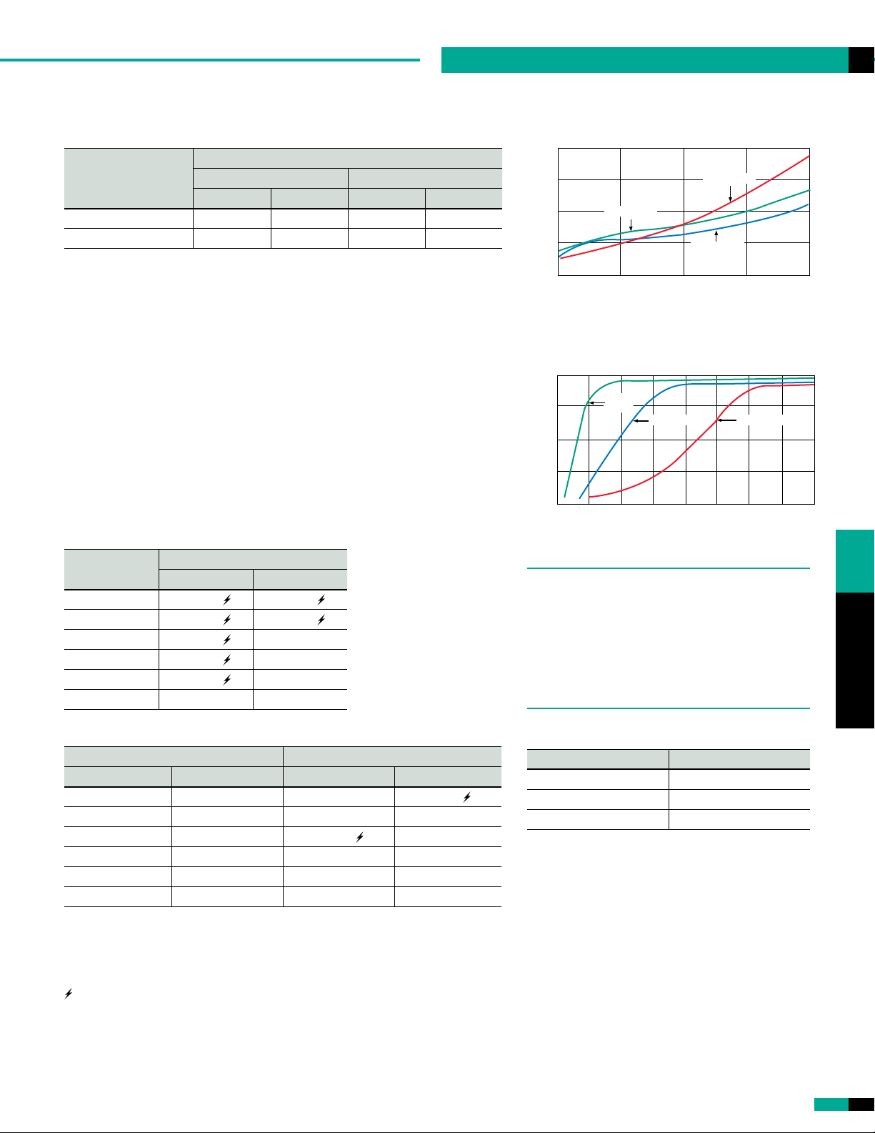
Pressure Drop - Typical
FS-925 Series
4
3
2
1
PRESSURE DROP (PSID)
0
0.05 .75
Tests conducted with units in vertical position (lead wires up) with water at
+70°F (21°C).
Part No. 26917
FLOW RATE - GPM
Part No. 26919
Part No. 26914
1.0 1.5 2
FS-926 Series
1.5
1.0
0.5
PRESSURE DROP (PSID)
0
0 10050 200150 300250 400350
Tests conducted with units in vertical position (lead wires up) with water at
+70°F (21°C).
FS-925 and FS-926 switches are U.L. Approved for
Class I, Division 2, Groups A, B, C, D hazardous
locations.
They are also available with FM-approved, explosionproof junction box for Class I, Division 1, Group
D hazardous locations. Units must be assembled
completely at GEMS.
U.L. Approved — File No. E183854
Part No.
26938
Part No. 26941
FLOW RATE - cc/Min.
Part No. 26944
Standard Wiring Color Code
Wire Color Terminal
Orange N.O.
Black Common
Red N.C.
FLOW SWITCHES
FS-925/926 Series / p2of2 / 30-SEP-14
Visit www.GemsSensors.com for most current information.
G-13
 Loading...