

Page 1
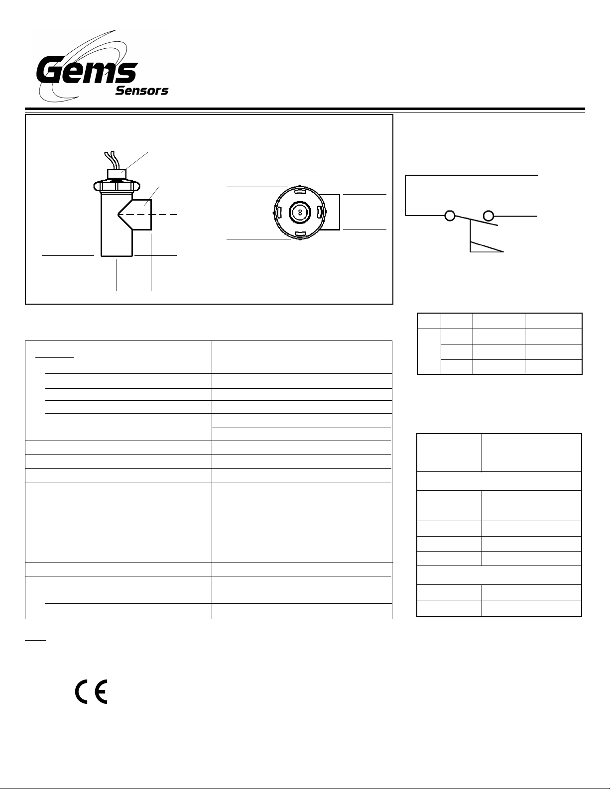
Ref. Dimensions . . .
Shuttle-Type Flow Switches
FS-500 Series
Instruction Bulletin No. 170660
Bonnet
!
3.80”
(96.5 mm)
!
!
Housing
!
1.8”
(45 mm)
!
!
1.48”
(37.5 mm)
Specifications . . .
Materials
Housing, Bonnet, Shuttle, Shuttle Cap
O-Ring
Spring
Retaining Clip
Operating Pressure, Maximum
Operating Temperature, Maximum
Set Point Accuracy
Set Point Differential
Switch (See “Switch Ratings”)
J-Box with 5A Relay
Inlet/Outlet Ports
Electric Termination
Pilot
J-Box
Top View
!
!
2.00”
(50.8 mm)
1.32”
(33.5 mm)
!
!
Polypropylene, Hydrolytically Stable
Glass-Reinforced
Viton® or Buna N
316 Stainless Steel
PH 15-7 Mo Stainless Steel
100 PSIG @ +70°F
50 PSIG @ +180°F
212°F (100°C)
± 20%
± 20%, Maximum
SPST, N.O. Pilot Duty: 20 VA,
120-240 VAC or VDC
120 VAC 50/60 Hz
Contacts: 5A-240 VAC Res.
1/3 HP - 120 VAC
5A - 28 VDC Res.
3/4” Female NPT
No. 22 AWG, 24” Zip Cord Lead Wires
6’ Cable
!!
!
!!
Typical Wiring Diagram . . .
Red
Red
SPST, N.O. at No Flow
Switch Ratings
Max. Resistive Load
VA
20
Volts
0 - 30
120
240
Amps AC
.4
.17
.08
Amps DC
Standard Models . . .
Part
Number
170231
170232
170233
170234
170235
J-Box w/5A Relay
175901
175902
Switch Actuation
Set Point on
Increasing Flow
Pilot Duty
0.25 GPM ± 20%
0.50 GPM ± 20%
1.00 GPM ± 20%
2.50 GPM ± 20%
5.00 GPM ± 20%
0.25 GPM ± 20%
0.50 GPM ± 20%
.3
.13
.06
Note: Standard units are designed with springs for positive return of the shuttle at no-flow condition. This allows the flow switch to
be mounted in any orientation, but actuation set points will vary from the stated values. Contact the Factory for further information.
This product is suitable for Class I and Class II applications only, per the requirements of standard EN60730 and
any additional specific requirements for a particular application or medium being sensed. Class I compliance of
metal bodied units requires a ground connection between the metal body and the earthing system of the
installation. Class I compliance of plastic bodied units in contact with a conductive medium requires that the
medium be effectively earthed so as to provide an earthed barrier between the unit and accessible areas. For
Class III compliance, a supply at safety extra-low voltage (SELV) must be provided. Please consult the Factory
for compliance information on specific part numbers.
Page 2
Installation ...
FS-500 flow switches are for use with metal or plastic piping systems and connect to piping via the 3/4" NPT mating
thread forms. The following guidelines are provided to assist with installation for a leak-free seal, without damage to
the unit.
1. Apply pipe thread sealant to the male pipe threads.
2. Thread the flow switch onto the male pipe thread until hand-tight.
3. Tighten pipe I to 1-1/2 additional turns.
4. If improper seal results, continue turning pipe into unit in 1/4 turn increments.
Do Not Exceed One Additional Turn
Recommended Pipe Sealants: a) Permatex® “No More Leaks” b) Teflon® Thread Tape
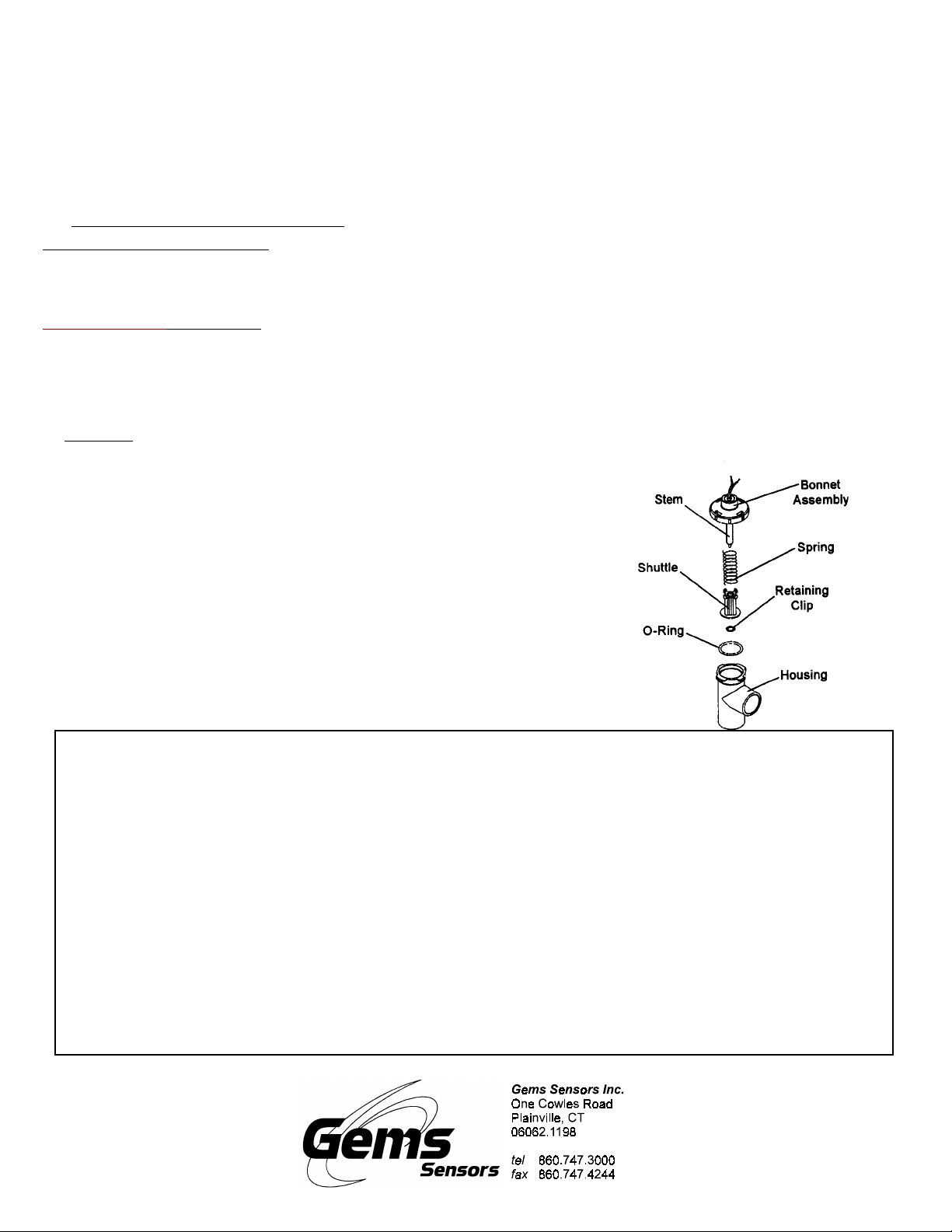
Maintenance ...
Disassembling for Cleaning: It is not necessary to remove the unit from the piping system. CAUTION: Make sure
the system is turned off and that no residual pressure remains in the piping.
1. The bonnet assembly (see diagram below) is removed by firmly grasping the housing and turning the bonnet 45°
counter-clockwise, as indicated on the top of the bonnet. This will unlock the mating tabs on the two parts.
2. The bonnet can now be pulled out of the housing. Be sure to pull on the bonnet, as damage can be done if the
lead wires are pulled.
Cleaning: Clean shuttle, stem, spring, retaining clip and inside of housing by lightly scraping and/or wiping. Check
0-ring, bonnet assembly, shuttle, and spring for damage. Consult Factory for replacement parts, if necessary.
To Reassemble Unit ...
1 . Be sure spring is properly set within clips on shuttle cap.
2. Reposition O-ring in counter-bored shoulder of housing.
3. Insert bonnet assembly into housing, allowing tabs on bonnet to clear
mating lugs on housing. Be sure bonnet stem end aligns with centering
feature in housing.
4. Bonnet assembly can be locked by firmly grasping housing and turning
bonnet 45* clockwise, as indicated on top of bonnet. This will engage
mating tabs on the two parts.
(See exploded view at right)
Important Points!
Product must be maintained and installed in strict accordance with
the National Electrical Code and GEMS product catalog and instruction bulletin. Failure to observe this warning could result in serious
injuries or damages.
An appropriate explosion-proof enclosure or intrinsically safe interface device must be used for hazardous area applications involving
such things as
dust and flammable materials.
Pressure and temperature limitations shown on individual catalog
pages and drawings for the specified flow switches must not be exceeded. These pressures and temperatures take into consideration
possible system surge pressures/temperatures and their frequencies.
Selection of materials for compatibility with the media is critical to
the life and operation of GEMS flow switches. T ake care in the proper
selection of materials of construction; particularly wetted materials.
(but not limited to)
ignitable mixtures, combustible
Life expectancy of switch contacts varies with applications. Contact GEMS if life cycle testing is required.
Ambient temperature changes do affect switch set points, since the
specific gravity of a liquid can vary with temperature.
Flow switches have been designed to resist shock and vibration;
however, shock and vibration should be minimized.
Liquid media containing particulate and/or debris should be filtered
to ensure proper operation of GEMS products.
Electrical entries and mounting points may require liquid/vapor sealing if located in an enclosed tank.
Flow switches must not be field repaired.
Physical damaged sustained by the product may render it unser-
viceable.
P/N 170660
Rev. D
 Loading...