

Page 1
Instruction Bulletin No. 205476
Flow Rate GPM
In-Line Flow Switches
FS-480 Series
Installation
All NPT threads should be installed using a suitable thread sealant (Teflon
tape or Permatex “No more Leaks”). Sealant must be kept out of unit
during installation. Ten diameters of straight run piping are recommended
upstream and downstream of the flow sensor.
The FS-480 end fitting is threaded to the body at assembly and torqued to
25 Ft. Lbs. If disassembly from a system is required, it is advisable to hold
the end fitting hex with a wrench to prevent sensor disassembly. If the
sensor should become disassembled as a result of uninstalling, retorque
the end fitting to 25 Ft. Lbs.
Specifications
Wetted Materials
Housing
Piston
Spring
O-Ring
Oper. Pressure, Max.
Operating Temperature
Required Filtration
Set Point Accuracy
Set Point Differential
Switch, See “Switch Ratings”
Inlet / Outlet
Electrical Termination
Stainless Steel
PPS Composite/Epoxy
316 Stainless Steel
Fluorocarbon
1000 PSI
-20°F to +275°F (120°C), (-28.8°C to +135°C)
100 Micron or Better
±20%, Maximum
20% Maximum
SPST , 20 VA
1/2” Tube, 1/2” & 3/4” NPT Male
No. 22 AWG, 24” to 26” PVC Cable
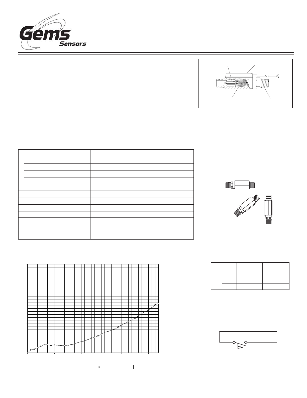
Piston
Inlet
Spring
Body
Outlet
End Fitting
FS-480 Flow Switches Can be Mounted
In Various Positions
Flow settings are based on a vertical
position (inlet port down), using water at
+70°F on increasing flow. Some variation
in set point actuation will occur in other
mounting orientations.
PSID Gems FS 480, 1GPM Setpoint
12
10
8
6
PSID
4
2
0
0123456789
Gems FS-480 P/N 204711
Switch Ratings
Max. Resistive Load
VA
20
Volts
0-30
120
240
Amps AC
.17
.08
Wiring Diagram
Normally Open
.4
Amps DC
.3
.13
.06
Page 2
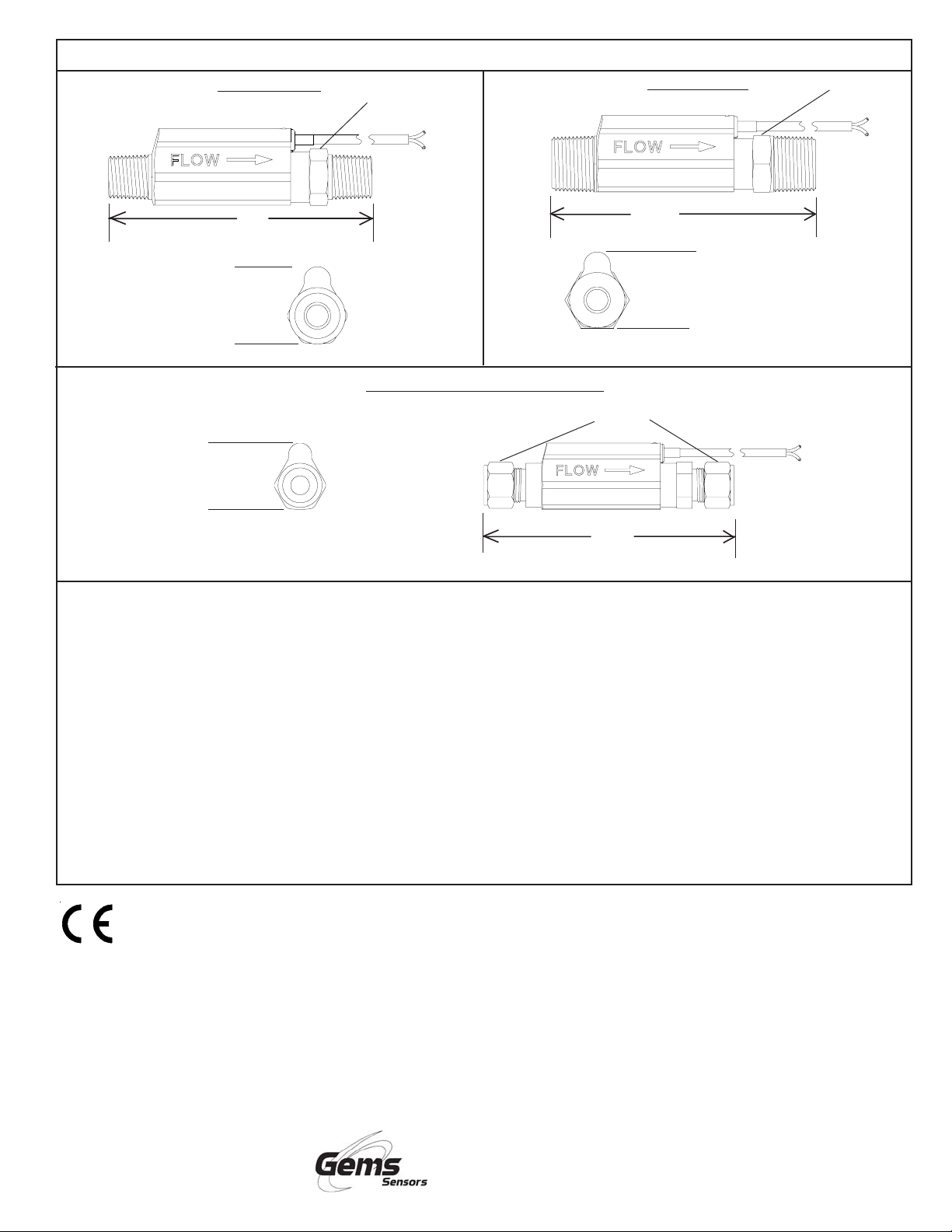
Dimensions
1/2” NPT Ports
4.94”
(125 mm)
↑
1.50”
(38 mm)
↓
↑
1.50”
(38 mm)
↓
7/8” HEX
1/2” Tube End Compression Fitting
(137 mm)
(126 mm)
7/8” HEX
5.4”
3/4” NPT Ports
4.95”
↑
1.50”
(38 mm)
↓
1 1/16” HEX
Important Points:
• Gems products must be maintained and installed in strict accor-
dance with the National Electrical Code and the applicable Gems
product instruction Bulletin that covers installation, operation and
proper maintenance. Failure to observe this information may result
in serious injury or damages.
• For hazardous area applications involving such things as, but not
limited to, ignitable mixtures, combustible dust and flammable
materials, use an appropriate explosionproof enclosure or intrinsi cally safe interface device.
• Please adhere to the pressure and temperature limitations shown
throughout this catalog for our level and flow sensors. These
limitations must not be exceeded. These pressures and tempera tures take into consideration possible system surge pressures/
temperatures and their frequencies.
• Selection of materials for compatibility with the media is critical to
the life and operation of Gems products. Take care in the proper
selection of materials of construction, testing is required.
This product is suitable for Class I and Class II applications only, per the requirements of standard EN60730 and any additional specific
requirements for a particular application or medium being sensed. Class I compliance of metal bodied units requires a ground connection
between the metal body and the earthing system of the installation. Class I compliance of plastic bodied units in contact with a conductive
medium requires that the medium be effectively earthed so as to provide an earthed barrier between the unit and accessible areas. For
Class III compliance, a supply at safety extra-low voltage (SELV) must be provided. Please consult the Factory for compliance information
on specific part numbers.
• NSF-approved sensors are made of materials approved for potable
water applications according to Standard 61.
• Stainless steel is generally regarded as safe by NSF and FDA.
• Life expectancy of switch contacts varies with application. Contact
Gems if life cycle testing is required.
• Ambient temperature changes do affect switch set points, since the
gravity of a liquid can vary with temperature.
• Our sensors have been designed to resist shock and vibration.
However, shock and vibration should be minimized.
• Filter liquid media containing particulate and/or debris to ensure the
proper operation of our products.
• Electrical entries and mounting points in an enclosed tank may
require liquid/vapor sealing.
• Our sensors must not be field-repaired.
• Physical damage sustained by product may render it unserviceable.
Return Policy
Returns are accepted on stock items up to 30 days from date of order. You must contact our Returns Department for a Return Authorization
(RA) number. Return the goods - freight prepaid - in the original container and include original packing slip. C. O. D. returns are not
accepted. Gems reserves the right to apply restocking charges.
Tel: 860-793-4357
Fax: 860-793-4563
Gems Sensors Inc.
One Cowles Road
Plainville, CT 06062-1198
Toll-Free: 1-800-378-1600
 Loading...