

Page 1
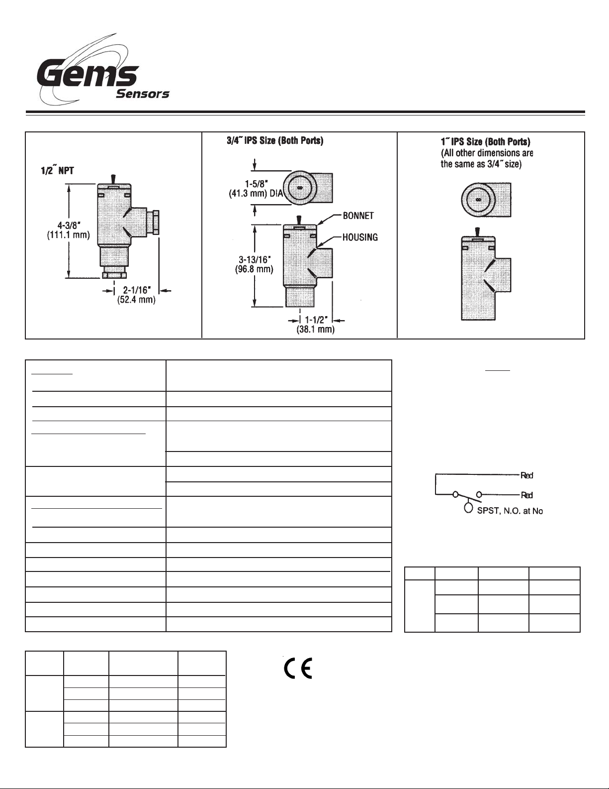
Dimensions . . .
Shuttle-Type Flow Switches
FS-400P Series
Instruction Bulletin No. 127430
Specifications . . .
Materials
Housing, Shuttle, Bonnet
O-Ring
Other Wetted Parts
Operating Pressure, Max.
-Clear Version
-Gray Version
Operating Temperature, Max.
-Clear Version
-Gray Version
Set Point Accuracy
Set Point Differential
*
Switch
Inlet/Outlet Ports
Mounting Attitude
Electric Termination
PVC
Buna N
Epoxy
120 PSIG @ +70°F to +100°F (+21°C to +37.8°C)
50 PSIG @ +101°F to 120°F (+38.3°C to +48.9°C)
150 PSIG @ +70°F to +100°F (+21°C to +37.8°C)
75 PSIG @ +101°F to 140°F (+38.3°C to +60°C)
+120°F (+48.9°C)
+140°F (+60°C)
±20%
20% Maximum
SPST, 20 VA, N.O. @ No Flow
1/2" NPT, 3/4" IPS, or 1" IPS
Vertical, Inlet Down
No. 22 AWG, 24" L., PVC Lead Wires
Notes
1. Care should be taken by specifiers
to ensure fluid compatibility with
the wetted materials listed.
2. Use of 150 micron filtration is
recommended
Typical Wiring Diagram . . .
*Switch Ratings
Max. Resistive Load
VA Volts
0-30
20
120
240
Amps AC
.4
.17
.08
Amps DC
.3
.13
.06
Standard Models . . .
PVC
Mat'l.
Clear
Gray
Port
Size
1/2" NPT*
3/4" IPS
1" IPS
1/2" NPT*
3/4" IPS
1" IPS
* 3/4" IPS Model with 1/2" NPT port adapter installed
Actuation on
Incr. Flow
0.5 GPM ±20%
0.5 GPM ±20%
2.0 GPM ±20%
0.5 GPM ±20%
0.5 GPM ±20%
2.0 GPM ±20%
Unit P/N
135805
135810
135815
127045
127050
127060
This product is suitable for Class I and Class II applications only, per the requirements of standard EN60730 and any additional specific requirements for a particular
application or medium being sensed. Class I compliance of metal bodied units
requires a ground connection between the metal body and the earthing system of the
installation. Class I compliance of plastic bodied units in contact with a conductive
medium requires that the medium be effectively earthed so as to provide an earthed
barrier between the unit and accessible areas. For Class III compliance, a supply
at safety extra-low voltage (SELV) must be provided. Please consult the Factory for
compliance information on specific part numbers.
Page 2
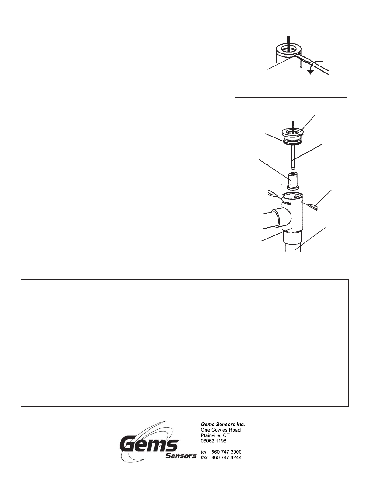
Maintenance ...
Removal of Bonnet From Housing ...
Disassembling for Cleaning ...
It is not necessary to remove the unit from the piping system.
CAUTION: Make sure the system is turned off and that no
residual pressure remains in the piping.
1. Carefully slide out the two retaining keys, using a screw
driver or similar tool.
2. Insert wide-bladed screwdriver in one of bonnet removal
slots and twist screwdriver slowly, forcing bonnet out of
housing. Do not pull on lead wires, as this can damage
unit.
Cleaning ...
Clean shuttle, stem and inside of housing by lightly scraping and/or
wiping. Be careful not to damage guide finders in bottom of housing
or flutes inside of shuttle. Check O-Ring, bonnet assembly and
shuttle, and replace if necessary See “Replacement Parts”
(below).Note: Replacement of O-Ring is recommended whenever
unit is disassembled.
To Reassemble Unit...
1. Assemble shuttle on bonnet stem, making sure large,
round end of shuttle is downward,
2. Hold shuttle on stem and insert bonnet squarely into
housing. Gently press bonnet into place.
3 Slide two retaining keys into slots in housing.
Bonnet
Removal Slot
O-Ring
Shuttle
Bonnet
Twist
Screwdriver
Bonnet
Assembly
Stem
Large Diameter
Must be Downward
Retaining
Key
Piping
System
*Replacement Parts.
Complete Repair Kit (Includes Bonnet
Ass’y,Shuttle,O-Ring)........P/N 127645
*Order by P/N from Gems
Product must be maintained and installed in strict accordance with
the National Electrical Code and GEMS product catalog and instruction bulletin. Failure to observe this warning could result in serious
injuries or damages.
An appropriate explosion-proof enclosure or intrinsically safe interface device must be used for hazardous area applications involving
such things as (but not limited to) ignitable mixtures, combustible
dust and flammable materials.
Pressure and temperature limitations shown on individual catalog
pages and drawings for the specified flow switches must not be exceeded. These pressures and temperatures take into consideration
possible system surge pressures/temperatures and their frequencies.
Selection of materials for compatibility with the media is critical to
the life and operation of GEMS flow switches. Take care in the proper
selection of materials of construction; particularly wetted materials.
Housing
Important Points!
Life expectancy of switch contacts varies with applications. Contact GEMS if life cycle testing is required.
Ambient temperature changes do affect switch set points, since the
specific gravity of a liquid can vary with temperature.
Flow switches have been designed to resist shock and vibration;
however, shock and vibration should be minimized.
Liquid media containing particulate and/or debris should be filtered
to ensure proper operation of GEMS products.
Electrical entries and mounting points may require liquid/vapor sealing if located in an enclosed tank.
Flow switches must not be field repaired.
Physical damaged sustained by the product may render it unser-
viceable.
P/N 127430
Rev. M
 Loading...