

Page 1
Shuttle-Type Flow Switches
Series FS-200/400
Instruction Bulletin No. 45523
Installation
Install FS-200 or FS-400 Series units in piping system using standard pipe fitting procedures. Be careful to keep
sealing compound out of the unit. Be sure to observe direction of flow - marked “IN” and “OUT” on housing. See
chart below for port and wrench hex. sizes.
Unless otherwise specified, standard FS-200 and FS-400 units are factory-calibrated with water. FS-200 and
FS-200 Adjustable units are installed horizontally, in line, with lead wires up. FS-400 and FS-400 Adjustable units are
installed vertically; lead wires up, as shown. 150 micron filtration is suggested for use with all units.
Specifications (FS-200 Series)
Wetted Materials
Housing
FS-200
FS-200 Adj.
Shuttle
Bonnet
Spring
Other Wetted Parts
Pressure Rating
Operating
Proof
Operating Temperature
FS-200
FS-200 Adj.
Repeatability
Set Point Accuracy
Set Point Differential
Switch*
Electrical Termination
#18 AWG, 24" L.
Polymeric
Jacket
B
A
1/2" NPT
Bronze or 316 Stainless Steel
Bronze
Teflon
Bronze or Stainless Steel
316 Stainless Steel
Viton
, Ceramic
400 PSIG @ 100°F (37.8°C)
800 PSIG @ 100°F (37.8°C)
-20°F to +300°F (-29°C to +148.9°C)
-20°F to +200°F (-29°C to +93.3°C)
1% Maximum Deviation
±10%
15% Maximum
SPDT, 20 VA
No. 18 AWG, 24" L., Polymeric Lead
Wires
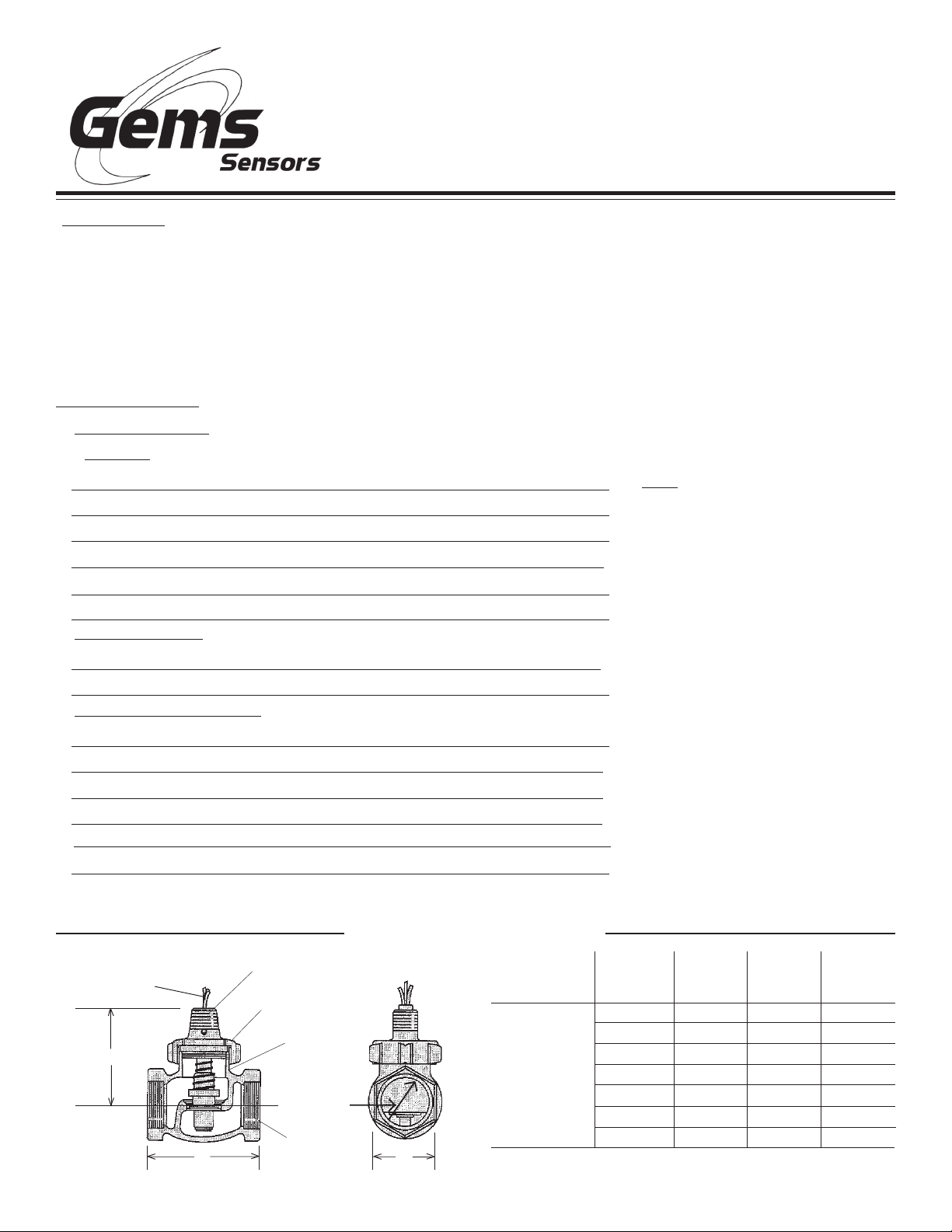
Dimensions (FS-200 Series)
Bonnet
Switch
Housing
Inlet Port
NPT Port
C
Note: Bonnet and shuttle
assembly should be removed
from unit during welding or
brazing.
(See bonnet assembly removal
under “Maintenance” on back
of sheet.)
*See "Electrical Data"
on inside pages
Port Size
NPT
1"
1-1/4"
FS-200
and
FS-200
Adjustable
Adjustable versions available in 1" port sizes only.
1-1/4" SS
1-1/2"
2"
2-1/2"
3"
"A" Dim.
3-1/4"
4"
4-1/2"
4-1/2"
5-3/8"
6-5/16"
7-3/8"
"B" Dim.Model
3"
3-3/16"
3-3/16"
3-1/2"
4"
4-1/2"
5-5/32"
"C" Dim.
(HEX)
1-25/32"
2-3/16"
2-3/16"
2-1/2"
3-3/32"
3-5/8"
4-3/8"
Page 2
Specifications (FS-400 Series) . . .
Wetted Materials
Housing
Shuttle
Spring
O-Ring
Other Wetted Parts
Pressure Rating, Max.
Operating
Proof
Operating Temperature
Repeatability
Set Point Accuracy
Set Point Differential
Switch
Inlet/Outlet Ports
Electrical Termination
*
Bronze
Delrin
316 Stainless Steel
Viton
Ceramic
400 PSI @ 100°F (+37.8°C)
800 PSI @ 100°F (+37.8°C)
-20°F to +180°F (-29°C to +82.2°C)
1% Maximum Deviation
±10%
15% Maximum
SPDT, 20 VA
3/4" NPT
No. 18 AWG, 24" L.,
Polymeric Lead Wires
*See "Electrical Data" below.
This product is suitable for Class I and Class II applications only, per the requirements of standard EN60730
and any additional specific requirements for a particular application or medium being sensed. Class I
compliance of metal bodied units requires a ground connection between the metal body and the earthing
system of the installation. Class I compliance of plastic bodied units in contact with a conductive medium
requires that the medium be effectively earthed so as to provide an earthed barrier between the unit and
accessible areas. For Class III compliance, a supply at safety extra-low voltage (SELV) must be provided.
Please consult the Factory for compliance information on specific part numbers.
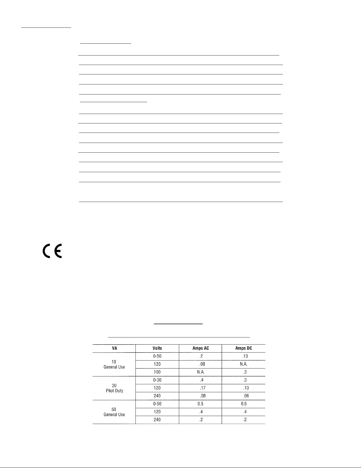
Electrical Data
Switch Ratings - Maximum Resistive Load
Page 3

Dimensions (FS-400 Series)
1-7/16"
HEX
1/2" NPT
3-27/32"
1-3/8"
1-3/8"
Pressure Drop Charts - Typical
FS-200 Series
1" NPT and 1-1/2" NPT Ports
PRESSURE DROP (PSID)
FLOW RATE: GPM
PRESSURE DROP (PSID)
2" NPT and 3" NPT Ports
FLOW RATE: GPM
Note: Tests conducted with units in horizontal position (lead wires up) with water at +70°F (21°C).
FS-400 Series
PRESSURE DROP (PSID)
FLOW RATE: GPM
Note: Tests conducted with units in vertical position (lead wires up) with water at +70°F (21°C).
Page 4

Electrical Connection . . .
Lead wires and 1/2" NPT or junction box with 1/2" NPT.
Flow Setting Adjustment . . .
(FS-200/400Adjustable and FS-400 Units.)
Maintenance . . .
Occasional cleaning when excessive contamination is
present in the liquid is the only maintenance normally
required. With system shut-down and no liquid in piping,
remove bonnet nut to disassemble unit for cleaning. It is
not necessary to remove unit body from the system.
Remove retainer ring “A” for complete shuttle disassembly.
Remove ring “B” to disassemble disc only.
Bonnet
Nut
Shuttle
Assembly
Disc
Retainer Ring "A"
Retainer
Ring "B"
Typical Wiring Diagram . . .
Standard units are normally supplied with adjustment set
at “minimum flow” - adjustment screw slot (and vane
within unit) in vertical position, as shown below. Adjustment may be made with unit on test stand or installed in
system. With liquid flowing at desired rate, adjust screw
in side of housing until unit just actuates. (Switch closes
or opens, as desired.)
Adjustment Screw with Slot in Min.
Flow Position. (Same for FS-200
Adjustable and FS-400 Adjustable
Units.
Flow
Switch
FS-200/400 Series
(Fixed & Adjustable)
Important Points!
Product must be maintained and installed in strict accordance with
the National Electrical Code and GEMS technical brochure and
instruction bulletin. Failure to observe this warning could result in
serious injuries or damages.
An appropriate explosion-proof enclosure or intrinsically safe
interface device must be used for hazardous area applications
involving such things as (but not limited to) ignitable mixtures,
combustible dust and flammable materials.
*** Warning: To prevent ignition of flammable or combustible
atmospheres, disconnect power before servicing.
Pressure and temperature limitations shown on individual catalog
pages and drawings for the specified flow switches must not be
exceeded. These pressures and temperatures take into consideration possible system surge pressures/temperatures and their
frequencies.
Selection of materials for compatibility with the media is critical to
the life and operation of GEMS flow switches. Take care in the
proper selection of materials of construction; particularly wetted
materials.
Life expectancy of switch contacts varies with applications. Contact
GEMS if life cycle testing is required.
Ambient temperature changes do affect switch set points, since
the specific gravity of a liquid can vary with temperature.
Flow switches have been designed to resist shock and vibration;
however, shock and vibration should be minimized.
Liquid media containing particulate and/or debris should be filtered
to ensure proper operation of GEMS products.
Electrical entries and mounting points may require liquid/vapor
sealing if located in an enclosed tank.
Flow switches must not be field repaired.
Physical damage sustained by the product may render it unserviceable.
P/N 45523
Rev. P
 Loading...