

Page 1

Warrick® Series DMS-470/570
Montoring Panels
Installation and Operation Bulletin
Table of Contents
Page 2 Installation Instructions: Safe Sensing Circuits
- Mounting Location
- Wiring: General Information
Page 3 Installation Instructions: Safe Sensing Circuits
- Wiring Diagrams
Page 4 Operation Instructions
- Control Panel Settings
- Setting the DIP switches
Form 725-B
Sheet P/N 7800824
Rev. A
Page 5 Operation Instructions
- Adjusting the Set Point Potentiometer
- Adjusting the Set Point Position: SVP-2 Sensor Only
Page 6 Technical Information
- Ordering Information
- Specifications
Page 7 Technical Information
- Module Replacement
Page 8 Operation Instructions
- Panel Operation
- Fuel/Water Pushbutton Operation
- Troubleshooting Guide
Page 9 Sample Wiring Diagram
- DMS-474-A-2 / DMS-574-A-2
Page 10 Sample Wiring Diagram
- DMS-478-A-1 / DMS-578-A-1
Page 11 Panel Dimensions
- DMS-474-A
-DMS-478-A
Page 12 Panel Dimensions
- DMS-574-A
-DMS-578-A
Page 2

Installation: Intrinsically Safe Sensing Circuit s
This bulletin should be used by experienced personnel as a guide to the installation of the Series DMS-470/570 alarm
panels. Selection or installation of equipment should always be accompanied by competent technical assistance. We
encourage you to contact Warrick or its local representative if further information is required.
Important
Before proceeding to install and wire the control panel,
read and thoroughly understand these instructions.
When the Series DMS 470/570 Monitoring Panel is installed according to these instructions, the panel will provide
intrinsically safe sensing circuits for interface into Class I, II. Division 1, Groups C, D, E, F and G hazardous locations. Electrical equipment connected to Series DMS 470/570 Monitoring Panel should not exceed maximum ratings
marked on product.
Mounting Location
The control must be situated in a non-hazardous area where an explosive atmosphere will not exist at any time.
Wiring: General Information
1. Intrinsically safe wiring must be kept separate from non-intrinsically safe wiring.
2. Intrinsically safe and non-intrinsically safe wiring may occupy the same enclosure or raceway if they are at least 2
inches (50mm) apart and separately tied down. Inside panels, field wiring terminals for intrinsically safe circuits
must be separated by at least 2 inches (50 mm) from non-intrinsically safe terminals.
3. For sensor wiring, use #14 or #16 A WG type MTW or THHN wire. By using these wire types in conjunction with
the following distance recommendations, you will not exceed the maximum capacitance for field wiring.
Use Table 1 as a guide for maximum wire runs.
Table 1
Model No.
DMS470/570
DMS470/570
4. Intrinsically safe terminals can be connected to any non-energy generating or storing switch device such as a
pushbutton, limit or float type switch or any Warrick electrode and fitting assembly.
5. All junction boxes and field wire terminations should be waterproof. Refer to appropriate sensor instructions for
details on how to install sensors.
6. An approved seal should be used at the point where the intrinsically safe control circuit wiring enters the hazardous area.
7. For additional guidance on “Hazardous Location Installation” and “Intrinsically Safe Devices”, consult ANSI/ISA
standard RP 12-6 or NEC articles 500-516.
Number of Sensor Wires Distance Per Channel
All 2 Wire Sensors
All 3 Wire Sensors
900 Feet
450 Feet
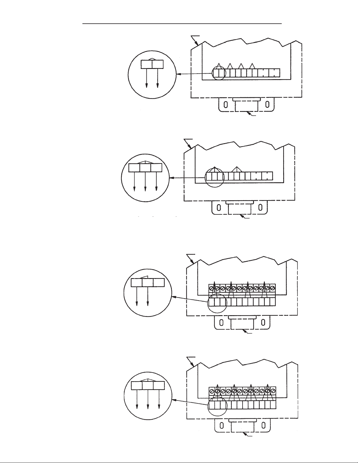
Sensor Wiring
Sensors: Wire the sensor devices to the Series DMS 470/570 Monitoring Panel as shown in figure 3-1 to 3-4. (A
separate rigid metallic conduit must be used to enclose the conductors of the intrinsically safe sensor
circuit. A conduit hub is provided on the bottom side of the enclosure for intrinsically safe wiring.)
2
Page 3
Installation: Intrinsically Safe Sensing Circuit s
Figure 3-1
Sensor #1
G1
S1
(BLK)
(RED)
2 Wire Sensor
Two (2) wire sensor connections for standard terminals
Figure 3-2
Sensor #1
G1S1
COMMON
(BLK)
FUEL
3 Wire Sensor
S2
(GRN)
WATER
(RED)
Enclosure
Enclosure
Sensor #1
S1
G1 S2 G2 S3G3S4 G4
Sensor #1
S1
G1 S2 G2 S3G3S4 G4
Sensor #2
Sensor #3
Sensor #2
Sensor #4
SIL
TEST
Conduit Hub for
Sensor Wires ONL Y!
SIL
TEST
Three (3) wire sensor connections for standard terminals
Conduit Hub for
Sensor Wires ONL Y!
For those models using the optional “check” push buttons, wire sensors per Figures 3-3 and 3-4.
Figure 3-3
Enclosure
Sensor #1
Sensor #4
C1
(BLK)
W1
(RED)
F1
2 Wire Sensor
Two (2) wire sensor connections for Fuel/Water terminals
Sensor #1
F1
C1W1F2
Sensor #2
Sensor #3
C2
C3
W2 F3
W3 F4 C4 W4
Conduit Hub for
Sensor Wires ONL Y!
Enclosure
Figure 3-4
Sensor #1
F1
C1
W1
Sensor #1
Sensor #2
Sensor #3
Sensor #4
FUEL
3 Wire Sensor
(BLK)
COMMON
(GREEN)
WATER
(RED)
Three (3) wire sensor connections for Fuel/Water terminals
F1
C1W1F2
C2
C3
W2 F3
W3 F4 C4 W4
Conduit Hub for
Sensor Wires ONL Y!
3
Page 4
Operation Instructions
Control Panel Settings
Before putting system into operation, DIP switches and potentiometers (set point) must be set to correctly match the
type of sensor you are using. (Ref to T able 4-1). The DIP switches and potentiometers are located above the sensor
terminal strip. (Figure 4-1)
DIP SWITCHES
INVERSE
INVERSE
FIELD WIRING
TERMINAL STRIP
MIN 1 MAX
SETPOINT
S1
1 DIRECT 2
G1 S2 G2 S3 G3 S4 G4 SILENCE TEST
MIN 2 MAX
SETPOINT
MIN 3 MAX
SETPOINT
3 DIRECT 4
SENSOR CONNECTIONS
MIN 4 MAX
SETPOINT
Figure 4-1
Setting the DIP Switches
T able 4-1describes applications vs. DIP switch settings. Each channel will have its own setting corresponding to the type of
sensor being used.
Table 4-1
APPLICATION
Double Wall Fiberglass
Fuel Sensing
Double Wall Fiberglass
Water Sensing
Double Wall S teel
Hydrocarbon/Water Sensing
Double Wall S teel
Liquid Sensing
Product Level Alarm
(Normally Closed Float)
Product Level Alarm
(Normally Open Float)
Monitoring Well
(Hydrocarbon V apor)
Detector
Unused Channel
Unknown
Unknown
WARRICK
SENSOR
DFP-25
DWP-25
DSP-2
DLP-2
LS-700/800
LS-700/800
SVP-2
None
Unknown
Normally
Open Switch
Unknown
Normally
ClosedSwitch
ACTIV ATION
CONDITION
Closes on Detecting Fuel
Closes on Detecting
Water
Closes on Detecting
Hydrocarbon or Water
Closes on Detecting
Liquid
Opens on Rising Level
Closes on Rising Level
Resistance Increases
on Detecting V apors
NA
Closed on Fault
Open on Fault
DIP SWITCH
SETTING
Inverse (“ON”)
Inverse (“ON”)
Inverse (“ON”)
Inverse (“ON”)
Direct (“OFF”)
Inverse (“ON”)
Direct (“OFF”)
Inverse (“ON”)
Inverse (“ON”)
Direct (“OFF”)
SET POINT
ADJUSTMENT
NA
NA
NA
NA
See Instructions on
set point setting
NA
See Instructions on
set point setting
NA
NA
Consult Factory
4
Page 5

Operation Instructions
Adjusting the Set Point Potentiometer
DIP Switch Set In Inverse (ON) Mode: When using a channel in Inverse(ON), there is no need to adjust the potentiom-
eter. The channel is automatically set to the maximum sensitivity.
DIP Switch Set In Direct (OFF) Mode: Turn the potentiometer clockwise until it reaches the end of its rotation. Do not
force the rotation. When the potentiometer is adjusted to this position, it is set to the maximum sensitivity. When using
SVP-2 Vapor Sensors, it may be necessary to reduce this sensitivity. Continue with the following instructions.
The Following Adjustment Applies only to those channels using an SVP-2 Vapor Sensor.
This adjustment will allow the alarm point to be set at a level just higher than the existing background contamination, thus
only indicating a potential new leak or spill condition.
CAUTION: As the V apor sensor reacts over time (Months) to background (Existing) cont amination, a false alarm
may occur. If this occurs, repeat the adjustment procedure.
1. With all appropriate potentiometers set to fill clockwise position, apply power to the panel and observe the state of the
indicator lights. Silence the audible alarm if necessary .
2. Upon power-up, no warning lights (audible alarm) should be on. If the warning lights are lit, proceed to step 3. S tarting
with the first channel using a vapor sensor, turn the potentiometer counter-clockwise until the warning light turns on.
(silence the audible alarm) Turn the potentiometer clockwise until the alarm light turn off. Turn the potentiometer an
additional 1/8 turn. Repeat this procedure for the remaining channels using vapor sensors.
3. If an alarm light remains lit, determine which channel is activated. Check the position of the DIP switch for the sensor
being used on that channel. Check the sensor wiring. Check for a true fault condition. Refer to troubleshooting guide for
further details.
Warning Light Off
(Step #3)
Warning Light On
(Step #2)
Start
(Step #1)
Supply Power
A weatherproof conduit hub is provided on the top of the enclosure for supply power wiring. Connect the incoming supply
HOT lead to the L 1 terminal, NEUTRAL lead to the L2 terminal and EARTH GROUND lead to the “G” Terminal.
Grounding
T erminal “G” on the supply line/load side terminal strip is a redundant system ground terminal and must be connected to
the earth ground buss of the panel’s AC supply line feeder .
Remote Alarm Contact
A set of SPDT dry contacts activates on fault when any one of the four (4) channels alarms. Using the conduit hub on
the top of enclosure, wire contacts to remote alarm or indicator , if applicable (terminals 7,8 and 9). For low voltage
circuits, wiring should not be run in the same conduit as high voltage circuits. Conduit should be teed immediately after
leaving enclosure.
Optional Auxiliary Contact Board
Additional 1/8 Turn
(Step #2)
Full Clockwise position
A SPDT auxiliary set of contacts are available for interfacing to remote alarms, computers, tank gauging systems, etc.
One set of contacts per channel are provided. Wire through conduit hub on top of the enclosure. (See Figure 9-1)
5
Page 6

Ordering Information
Technical Information
General
One set of auxiliary contacts is standard with every (4) four channels supplied. A common test button is included as st andard
for every (4) four channels supplied. The Fuel/Water check buttons listed below are used to distinguish water or hydrocarbon
when three1 wire sensors are used.
DMS-47X-X-X-X
DMS-57X-X-X-X
NO. OF CHANNELS FUEL / W A TER CHECK
AUXILIARY CONT ACTS
PUSH BUTTONS
1 1 CHANNEL
2 2 CHANNELS
3 3 CHANNELS
4 4 CHANNELS
8 8 CHANNELS
12 12 CHANNELS
A NO CHECK BUTTONS
B CHECK BUTTONS 1-4
C CHECK BUTTONS 1-8
D CHECK BUTTONS 1-12
F CHECK BUTTONS 1
G CHECK BUTTONS 1-2
H CHECK BUTTONS 1-3
1 NO AUX. CTS.
2 AUX. CTS. 1-4
3 AUX. CTS. 1-8
4 AUX. CTS. 1-12
6 AUX. CTS. 1
7 AUX. CTS. 1-2
8 AUX. CTS. 1-3
Specifications
Primary AC Supply Line: 120 VAC (plus)+ 10%, (minus) -15%, 50/60 Hz.
Probe V oltage: Nominal 12 VAC @ 6ma RMS
Sensitivity Range: 0 -50,000 Ohms maximum specific resistance
Temperature: (minus) -400 to (plus) +150° F
Remote Alarm Contact: (Terminals 7 N.C., 8 com & 9 N.O.)
Contact Design: SPDT (1 form C): one normally open (N.O.) and one normally closed.
Contact Ratings: 120 V AC or 30 VDC, 5A 1/10 H.P.
Contact Life: Electrical @ rated load = 100,000 cycles minimum. Mechanical = 10 million cycles minimum.
ENCLOUSURE
- NEMA 3R
N4 NEMA 4
N4XFG NEMA 4X FIBERGLASS
Electronics Module: Solid state components epoxy encapsulated in a black nylon shell
Module Terminals:
Screw Terminal Torque Rating: 5 -6 Inch/ Pounds
Field Wiring: Removable terminal strip, containing a size 4 (four) pan head screw with a clamping plate.
Will accept up to one #14 AWG wires per terminal.
Factory Wiring: Removable terminal strip will accept up to one #14 AWG wires per terminal.
Optional Auxiliary Board:
Auxiliary Contacts: One relay contact per channel.
Contact Design: SPDT (1 form C): one normally open (N.O.) and one normally closed (N.C)
Contact Ratings: 120 VAC or 30 VDC, 10A 1/3 H.P.
Contact Life: Electrical @ rated load = 100,000 cycles minimum. Mechanical = 10 million cycles minimum.
Auxiliary Board Terminals:
Field Wiring: Removable terminal strip will accept up to one #14 AWG wire per terminal.
Auxiliary Board Connection: Eight (8) pin wire harness connector.
Optional “Check” Pushbutton Board:
Terminals: Size four (4) pan head screw with a clamping plate, will accept up to one #14 AWG wire per
terminal. “Check” pushbutton board and module strip should be removed as an assembly from electronic
module.
6
Page 7

Technical Information
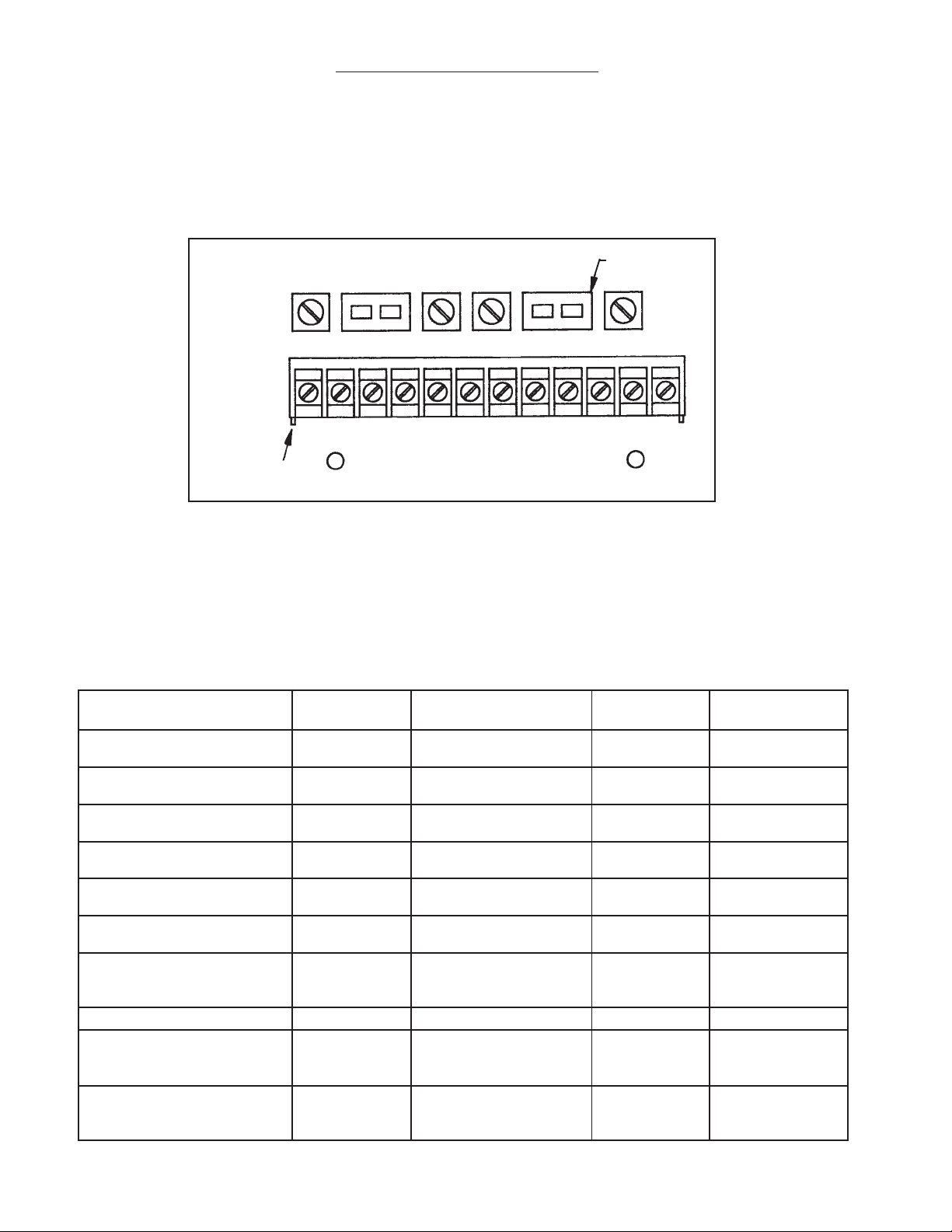
Module Replacement
If the electronic module needs to be replaced:
1. Turn off power to the control panel.
2. Remove the metal barrier located across the center of module.
3. Remove all field wiring terminal blocks from the electronic module. The field wires do not need to be removed
from the terminal blocks to do this. The terminal blocks separate at midpoint on the vertical as shown in
Figure 7-1.
Field Wiring
T erminal Block
Module Replacement Diagram
T erminal S trip
Removal
Factory Wiring
T erminal Block
T erminal Strip
Removal
Removable T erminal Strips
Separation
Point
Factory Wiring
Field Wiring
Figure 7-1
4. Remove the factory wiring terminal blocks from the electronic module. The factory wiring does not have to be
removed to do this. The terminal blocks separate from the module at the board surface as shown in Figure
7-1.
5. Remove the four (4) machine screws from the base of the electronic module. The module can now be
removed from the control panel.
6. Replacement Module: 47D1 BXXX
7. Install a new module and reinstall all of the terminal blocks. Make sure that all factory and field wiring is in
place.
8. Reinstall the metal barrier across the center of the module.
9. Set all DIP switches and potentiometers according to previous instructions.
7
Page 8

Operation Instructions
Panel Operation:
With sensors wired to control panel and power applied, the normal light (yellow) should be lit. Individual warning
lights (amber) are provided for each channel. If a sensor detects a fault condition, the normal light will deenergize. The appropriate warning light will then energize and the audible alarm will sound. To silence the
alarm, push the SILENCE pushbutton. The WARNING light will remain lit until the fault condition is cleared. If a
second fault occurs before the first fault is cleared, the appropriate WARNING light will energize and the alarm
will sound. Each successive fault will cause the alarm to sound.
A TEST button is supplied to test the circuitry in the panel. To perform a test, push the TEST pushbutton and
hold. The NORMAL light will go off. All W ARNING light s in that bank will light and the alarm will sound.
Releasing the TEST pushbutton will return the system to a normal condition.
All panels contain a master fault contact, which will activate if any one of the channels sees a fault condition.
This can be used to trigger a remote alarm or cash register. The master fault cont act will reset when the
SILENCE pushbutton is pressed.
If optional auxiliary contacts are used, a SPDT dry contact is provided for each channel. To reset these contacts,
the fault condition must be cleared.
Fuel/ Water Pushbutton Operation:
If the audible alarm is energized, it can be silenced by momentarily depressing the SILENCE pushbutton.
However, to determine if this is a FUEL or WATER leak, continue with the following instructions.
1. WA TER PUSHBUTT ON: (When audible alarm is already silenced.) Momentarily depress the WATER pushbutton. If, after
release of the button the audible alarm energizes, this indicates a water leak. The audible alarm can be silenced again by
depressing the SILENCE pushbutton. If pushing the fuel button has no effect, continue to step 2.
2. FUEL PUSHBUTTON: (When audible is already silenced.) Momentarily depress the fuel pushbutton. If after release of the
button the audible alarm engergizes, this indicates a fuel leak. The audible alarm can be silenced again by depressing the
SILENCE pushbutton.
Troubleshooting Guide:
A test button is used on all models to test the control panel. If the system is powered up and there are no fault conditions, the
normal contact should be lit. The warning lights and alarm should be de-energized. On pushing the test button, the normal
lights go off, all warning lights in that bank should light up and the alarm should sound. Push the silence pushbutton to deenergize the alarm. Releasing the test pushbutton should return the system to a normal condition.
If a WARNING light has been activated and a true fault condition is not found:
1. Recheck position of DIP switch (Figure 4-1, Table 4-1). If correct continue.
2. If the DIP switch is in the Inverse Mode (“ON”) position, removing the sensor wiring at the terminal block should deactivate the alarm. Shorting the terminal points should activate the alarm. If this does not happen, replace the electronic
module.
3. If the DIP switch is in the Direct Mode (“OFF”) position, removing the sensor wiring at the terminal block should
activate the alarm. Shorting the terminal points should de-activate the alarm. If this does not happen, replace the electronic module.
4. If the above tests show the operation of the module is correct and the alarm condition persists, repeat steps 2 and 3 for
all field terminal locations. This should isolate the problem to the appropriate area (field wiring, sensor). Replace or
repair appropriate equipment.
88
Page 9

SilenceTest
Sample Wiring Diagram
DMS-474-A-2 / DMS-574-A-2
TEST
SILENCE
4
Sensor
3
Sensor
2
Seal Off Fitting
Sensor
Hazardous Area
1
Sensor
S1
G1 S2 G2 S3 G3 S 4 G4
ISR1
Intrinstically
Safe Control
Series 47D1A-0A4
Alarm #1
Alarm #2
Contact
Rating
10A, 1/3 HP
VA C
Aux
Connector
C
1234
Alarm #3
NC C NO
CHNL #1
56
Alarm #4
NC C NO
CHNL #2
7
NC
Normal
NC C NO
CHNL #3
8
NO
C
Alarm
9
L1 L2
NC C NO
CHNL #4
G
L1 Hot
Note:
Terminals 7,8 & 9 are single pole
double throw dry contacts designed for
remote alarms.
Terminals 8 & 9 CLOSE ON FAULT
Terminals 8 & 7 OPEN ON FAULT
Contacts clear when the SILENCE
pushbutton is depressed or when the
fault condition is cleared.
CONT ACT RA TING: 5A 1/10HP 120V AC
Ground
L2 Neutral
120 V AC
Figure 9-1
9
Page 10

Sample Wiring Diagram
DMS-478-A-1 / DMS-578-A-1
Alarm #1
A
Alarm #2
A
Alarm #3
A
Alarm #4
A
Normal
Y
Alarm
Alarm #1
A
Alarm #2
A
Alarm #3
A
Alarm #4
A
Normal
Y
NC
C
NO
C 1 2 3 4 5 6
NC
C
NO
ISR1
Series 47D1B04
Instrinsically
Safe Control
TEST
SILENCE
G4S4
7
8
9
L1
L2
G
G3S3
G2S2
TEST
G1S1
SILENCE
Seal Off Fitting
ISR2
Series 47D1B04
Sensor
Instrinsically
Safe Control
C
1 2 3 4 5 6
7
8
9
L1
L2
G
TEST
SILENCE
G4S4
G3S3
G2S2
G1
S1
Sensor
1
Hazardous Area
TEST
Sensor
2
SILENCE
Sensor
3
4
10
120 VAC
L1 Hot
L2 Neutral
Ground
Note:
Terminals 7,8 & 9 are single pole
double throw dry contacts designed for
remote alarms.
Terminals 8 & 9 CLOSE ON FAULT
Terminals 8 & 7 OPEN ON FAULT
Contacts clear when the SILENCE
pushbutton is depressed or when the
fault condition is cleared.
CONT ACT RA TING: 5A 1/10HP 120V AC
Figure 10-1
Seal Off Fitting
Sensor
Sensor
1
2
Hazardous Area
Sensor
3
Sensor
4
Page 11

Panel Dimensions
NEMA 3R
10 X 8 X 6 ENCLOSURE
DMS-474-A
NEMA 3R
12 X 12 X 6 ENCLOSURE
NORMAL
ALARM 1
TEST
DMS-474
ALARM 2 ALARM 3
3.00”
8.00”
Figure 11-1
ALARM 4
11.00”
10.00”
SILENCE
DMS-478-A
NORMAL
ALARM 1
ALARM 2 ALARM 3
TEST
DMS-478
ALARM 4
SILENCE
Figure 11-2
3.00”
NORMAL
ALARM 1
12.00”
ALARM 2 ALARM 3
TEST
ALARM 4
12.00”
13.00”
SILENCE
11
Page 12

Panel Dimensions
DMS-574-A
DMS-578-A
NEMA 3R
10 X 8 X 6 ENCLOSURE
NEMA 3R
12 X 12 X 6 ENCLOSURE
NORMAL
ALARM 1
TEST
Figure 12-1
DMS-574
ALARM 2 ALARM 3
SILENCE
3.00”
8.00”
ALARM 4
11.00”
10.00”
NORMAL
ALARM 1
ALARM 2 ALARM 3
TEST
DMS-578
ALARM 4
SILENCE
Figure 12-2
3.00”
NORMAL
ALARM 1
12.00”
ALARM 2 ALARM 3
TEST
ALARM 4
12.00”
13.00”
SILENCE
12
Gems Sensors Inc.
One Cowles Road
Plainville, CT 06062-1198
Tel: 860-793-4579
Fax: 860-793-4580
 Loading...