

Page 1
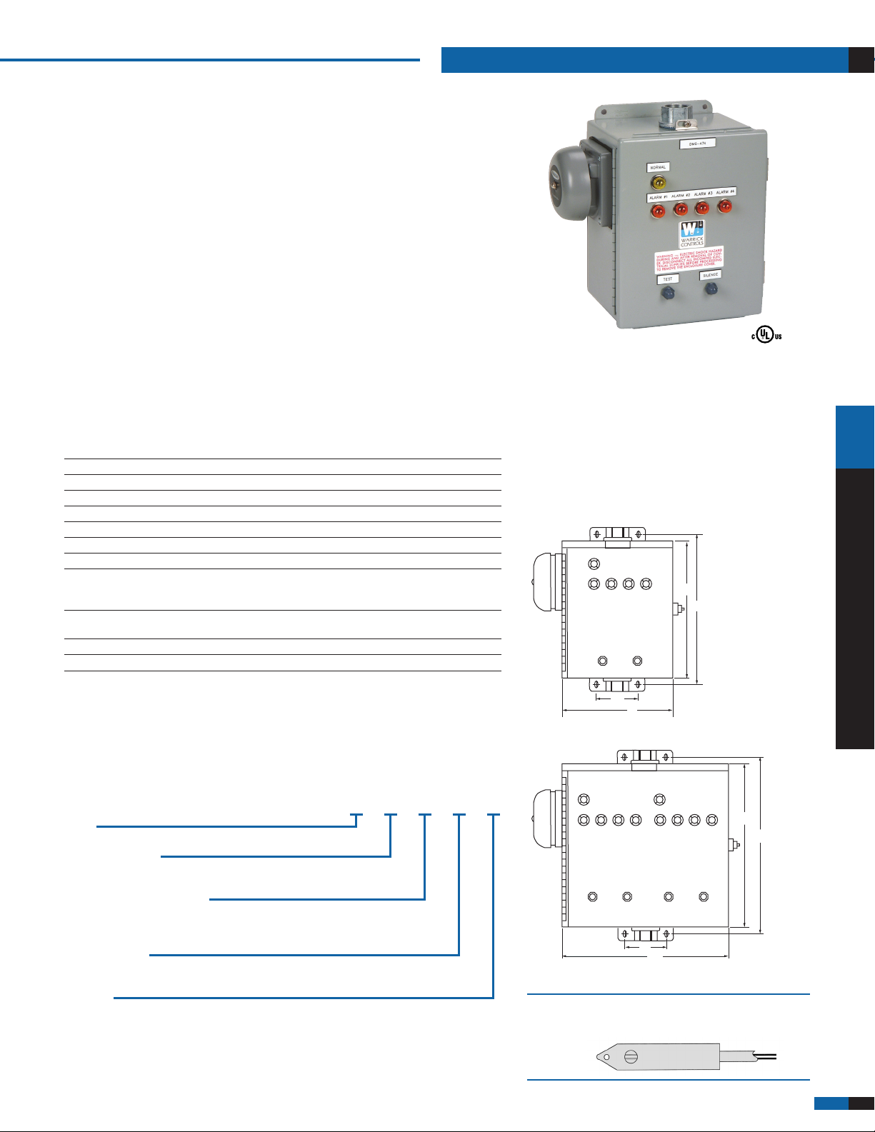
DMS-478
NORMAL
1 234
10˝
11
˝
8˝
3˝
TEST
SILENCE
DMS-478
NORMAL NORMAL
12341234
12˝
13
˝
12˝
3˝
TEST
SILENCE
TEST
SILENCE
DMS 470/570 Series
Leak Detection Systems
for UST and AST Storage Tanks
Low Cost
U.L. Approved Intrinsically Safe
Easily Maintained
Audio/Visual Alarm
The DMS 470/570 monitoring systems are ideal for a number of UST and AST
monitoring applications. The DMS 470 includes an audible bell while the DMS 570
uses a piezoelectric horn. Applications include vapor monitoring of monitoring wells
surrounding single wall tanks, high/low product level alarms, vapor sensors for single
wall piping and piping sump sensors for double wall piping.
Auxiliary Contacts
Auxiliary alarm contacts are also available for interfacing to remote alarms,
computers, tank gauging systems, phone dialers, etc.
Specifications
Contact Design SPDT (1 form C), one normally open, one normally closed
Contact Rating 120 VAC or 30 VAC, 10A, 1/3 h.p.
Sensitivity Range 0-50,000 ohms max. specific resistance
Remote Alarm Contact Terminals; 7 N.C., 8 com, 9 N.O.
Primary Voltage 120 VAC (+10%/-15%) 60 Hz
Probe Voltage Nominal 12 VAC @ 6ma RMS
Optional Auxiliary Contacts One relay contact per channel
Optional “Check”
Push Button Board* Terminals: Size four (4) pan head screw with a clamping plate;
will accept up to 14 AWG.
Enclosure Type NEMA 3R; optional NEMA 4, Weather-proof;
optional NEMA 4X, Fiberglass
Temperature -40°F to +150°F (-40°C to +65.5°C)
Approval U.L. Listed (U.L. 913) E120178
*For media discrimination in-storage tank
pANEl CONTROlS AND AlARmS
Applications
Above Ground Fuel Storage Tanks (AST)
• LeakDetection • Overll
• Rell
Underground Fuel Storage Tanks (UST)
• HighLevelAlarm • LeakDetection
• PipingSumps • MonitoringWell
Dimensions
4 Channel
How to Order
Use the Bold characters from the chart below to construct a product code. One set of
auxiliary contacts is standard with every four (4) channels supplied. A common test
button is standard for every four (4) channels supplied. The fuel/water check buttons
listed below are used to distinguish water or hydrocarbon when three wire sensors are
used. Each sensor or detection point requires its own channel.
DMS XX X X X XX
Series
47 audible bell; 57 piezoelectric horn
Number of Channels
1 1 Channel; 2 2 Channels; 3 3 Channels; 4 4 Channels;
8 8 Channels; 12 12 Channels; 16 16 Channels;
Fuel/Water Check Push Buttons
A No Check Buttons; B Check Buttons, 4; C Check Buttons, 8;
D Check Buttons, 12; F Check Button, 1;
G Check Buttons, 2; H Check Buttons, 3
Auxiliary Contacts
1 None; 2 Aux. Contacts, 4; 3 Aux. Contacts, 8; 4 Aux. Contacts, 12;
6 Aux. Contact, 1; 7 Aux. Contacts, 2; 8 Aux. Contacts, 3
Enclosure
N4 NEMA 4 option; N4XFG NEMA 4X fiberglass option
Visit www.GemsSensors.com for most current information.
8 Channel
See Our Interstitial Tank Monitoring Products
on page A-22.
WARRICK CONDUCTIVITY SENSORS
E-3 1
 Loading...