

Page 1

Introduction
Your Gems Sensors DM28 DC Process is one model in a family of 1/8 DIN units
which offers breakthrough display technology as well as easy-to-program single-line
parameters. Designed to provide instant visual feedback regarding an application’s
key input value, the DM28 not only has a 0.71” high LED display (27% larger than
other 1/8 DIN units), but also the ability to change display color based on process
status (programmable parameter in Operation Mode). Easy programming is made
possible via a help function and a secondary legend display.
This manual will guide you through the installation and wiring of your DM28 unit
with information on proper panel mounting and rear ter minal layout and wiring
instructions. In addition, the instrument’s operation, programming, and
configuration modes are thoroughly explained. The Operation Mode provides day to
day operation and allows editing of preset values. The Program Mode enables the
configuration of various parameters prior to initial operation. These parameters
include those for basic configuration as well as other settable features which will
enhance the functionality
and usability of the device.
The Configuration Mode
allows selection of how
outputs and special
functions are utilized.
Technical Manual
This manual also provides
information on the DM28 DC
Process' alarms; transistor,
relay, and linear outputs;
product specifications; and
ordering and warranty
procedures.
Features
• 0.71” high digit LED display
• Programmable color change display based
on an event
• Programmable help function and secondary
legend display
• High and low alarm outputs
• mA inputs to 50mA, DCV inputs to ±10
Volts and ±100 mV
• Tare function
• Standard outputs: two NPN transistors &
one relay (optional 2nd relay)
• 100 ms sample time with 0.03% accuracy
• CE approved
Index
Installation
Panel Mounting page 2
Wiring page 3
Operation
Front Panel page 4
Operation Mode page 5-6
Programming
Program Mode page 7-10
Configuration
Configuration Mode page 11-14
Appendix A
Specifications page 15
General
Ordering Information page 16
Warranty page 16
182016
DM28-2XXXX
DC Process
Page 2
INSTALLATION
PANEL MOUNTING
Gems Sensors
OP1
OP2
48mm
82344
100mm
Mounting Grooves
96mm
PGM
RST
92mm +0.5 -0.0
CUTOUT
14 15 16 17 18 19 20
10 11 12
10mm
PANEL
45mm
+0.5 -0.0
SIZE
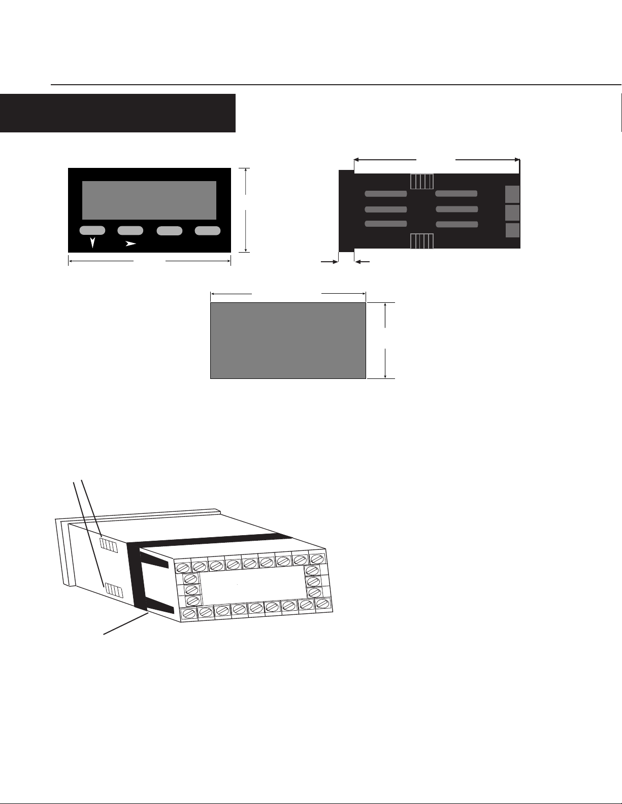
The instrument can be mounted in a panel with a thickness of up to 6mm. The
cutout(s) should be made based on the recommended panel opening illustrated in the
drawing above.
Insert the unit in the panel through the cutout. Ensure that the
panel gasket is not distorted and the instrument is positioned
squarely against the panel. Slide the mounting clamp into place
on the instrument, as shown to the left, and push it forward until
it is firmly in contact with the rear face of the mounting panel and
the tabs on the bracket arm are seated in the mounting grooves
on the side of the unit.
22
23
24
2
345 678
The electronic components of the instrument can be removed from
the housing after installation without disconnecting the wiring.
To remove the components, grip the side edges of the panel and
pull the instrument forward. Take note of orientation of the unit
for subsequent replacement in the housing.
Bracket Arm
2
Page 3
INSTALLATION
WIRING
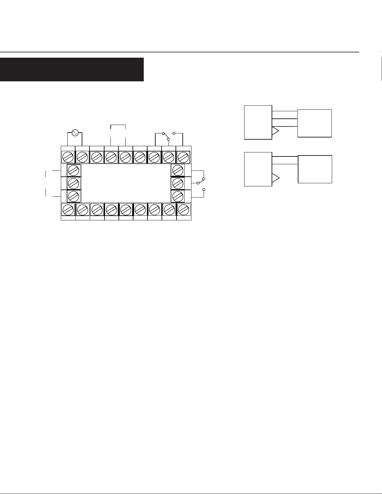
REAR TERMINAL CONNECTIONS
Digital Input
B A
45678
Relay 1
3
22
23
24
2
Relay 2
Linear
Output
Power Supply
+
-
14 15 16 17 18 19 20
10 1 1 12
Control/Digital Inputs
A digital input board, which utilizes Terminals #16 &
#17, can be installed as an option. The input can be
programmed in Configuration Mode to perform one of
two functions:
NPN Out 2
Common
NPN Out 1
Aux. Po wer +
Aux. Power -
V +
mV / mA +
mV / V / mA -
- Tare: When activated, the unit will create an
automatic offset by referencing the currently
Transistor Outputs
Your unit comes standard with 2 NPN outputs which are activated by
each of the alarms. Transistor Output 1, which is tied to Alar m 1, is
on Terminal #7. T ransistor Output 2, which is tied to Alarm 2, is on
Terminal #9. Ter minal #8 serves as the common connection for both
transistor outputs.
Input Power
For an AC powered unit, Terminal #13 serves as the line or Hot side
measured value as the new zero point.
- Security: When activated, the Program Mode
will not be accessible from the front
panel.
connection for AC powered units and as the positive side for DC
Relay Outputs
Your unit comes standard with a relay output which is tied to Alarm
powered units. The neutral side for AC powered units and the
negative side for DC powered units are connected to Terminal #14.
1. Terminal #19 is NC, Ter minal #20 is common, and Terminal #21
is NO. A second relay output tied to the operation of Alarm 2 can be
added as an option at the time of order or later installed in the field.
Terminal #22 is NC, Ter minal #23 is common, and Terminal #24 is
NO.
DC Inputs
Your unit accepts millivolt, Volt, or milliamp DC ranges. Terminal
Linear Output
An option board may be installed that provides a 10 bit linear output
signal relative to the Process Value. Terminal #12 is the positive side
of the connection, and Terminal #10 is the negative side. The default
range of the output is 4-20 mA, but can be changed via the
Configuration Mode to 0-20 mA, 0-10 VDC, 2-10 VDC, 0-5 VDC, or 1-
5 VDC.
#1 is used for mV, V, or mA negative inputs. Terminal #2 is used for
V positive inputs, while Terminal #3 is used for mV or mA positive
inputs.
Meter
Meter
6
2
5
1
6
3
1
5
Exc
Out
Common
Jumper
Jumper
3 -Wire
Voltage
Sensor
+
2 -Wire
4-20 mA
Transmitter
Terminals 4, 11, & 15 are not used.
3
Page 4
OPERATION
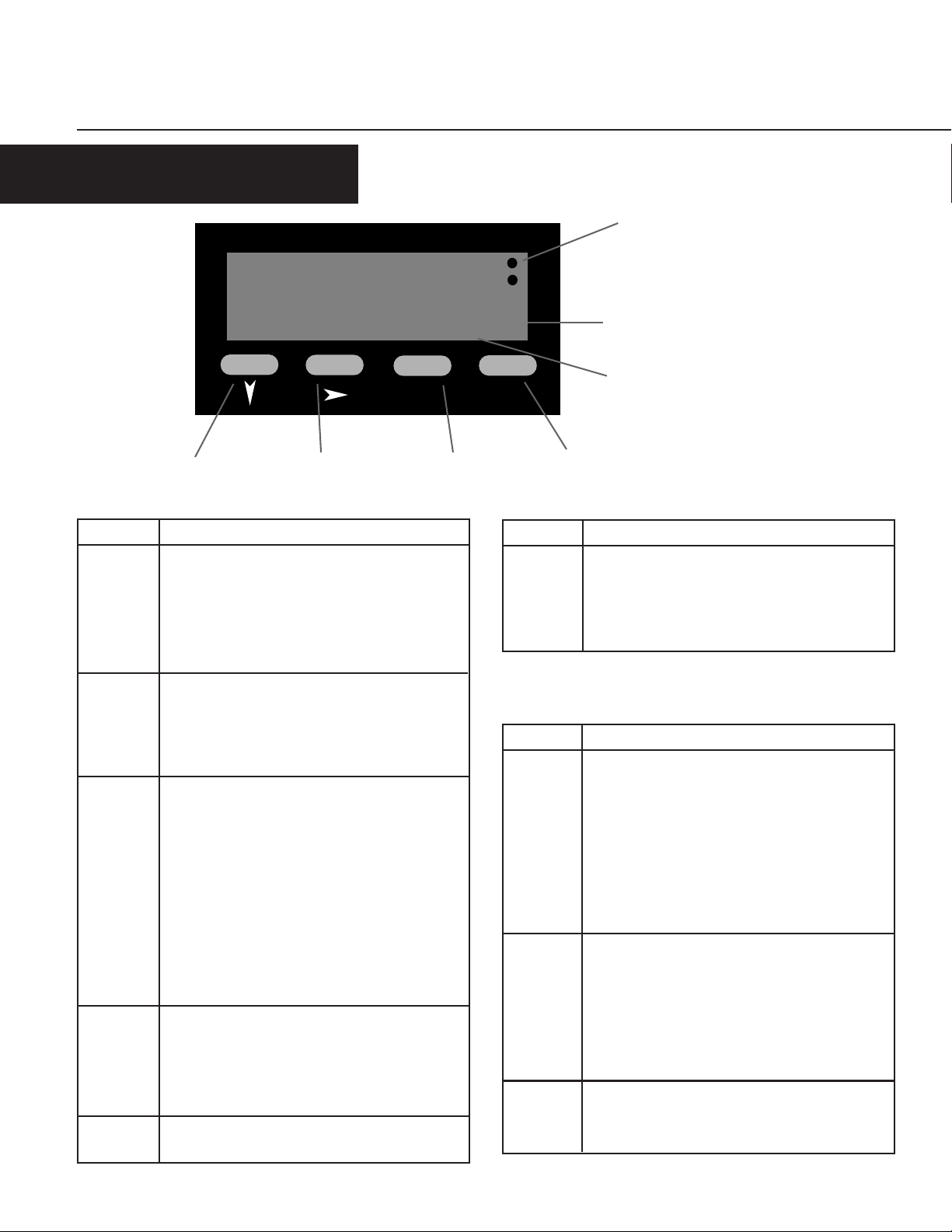
FRONT PANEL
Gems Sensors
Output Indicators
OP1
OP2
82345
PGM
Down Key Scroll Key Program Key Reset Key
Key Functions
Key
Down
Scroll
Program In Operation Mode: Used to move between the process
Reset In Operation Mode: Resets a latched alarm if pressed
Down &
4
Scroll
In Operation Mode: Used in Edit Operation to
decrement the digit highlighted by the Scroll key.
In Program & Config. Modes: Used in Edit Operation to
decrement the digit highlighted by the Scroll key, if the
setting is a numerical value, or present the next in the
series of choices for that parameter .
In All modes: Moves the unit into Edit Operation,
which is indicated by the left most digit flashing.
Successive presses of the key are used to move to the
digit to be edited. Wrap around will occur from least
significant digit to most significant digit.
value display & the presets and to enter an edited
preset value. Holding the key down for 3 seconds will
cause the unit to enter Program Mode if not
disabled by digital input.
In Program Mode: Used to move from one parameter
to the next and enter the edited parameter values.
Holding the key down for 3 seconds will cause the unit
to return to Operation Mode.
In Config. Mode: Used to move from one parameter to
the next and enter the edited parameter values.
while the process value is being viewed. Pressing this
key while viewing the max, min, or elapsed time
value will cause those values to be reset.
In Program & Config. Modes: No function.
In All modes: Will abort an Edit Operation and return
the preset/parameter to its previous value.
Function
H
Secondary Display
Primary Display
RST
Key Functions
Key
Down &
Program
Key
Primary In Operation Mode: Default display is the Process
Secondary In Operation Mode: Provides an alpha or numeric
Output
Indicators
In Config. mode: Holding down both keys for 3 seconds
will cause the unit to return to Operation Mode.
In Operation & Program Modes: Holding down both
keys for 3 seconds will cause the unit to enter to
Config. Mode.
Display Functions
V alue. Can be scrolled using the program key to
display other Operation Mode values. If the "Help"
function is enabled, this display will first show the
parameter description for 3 seconds (example - page 6).
In Program & Config. Modes: Displays the value or
selection for the current parameter . If the "Help"
function is enabled, this display will first show the
parameter description for 3 seconds (example - page 7).
indentification of the value on the primary display.
This display is blank when the Process Value is being
shown.
In Program & Config. Modes: Provides a 1 digit alpha or
numeric character to indicate which parameter value is
being shown on the primary display.
In Operation Mode: Illuminates when Alarm 1 and
or Alarm 2 is active.
In Program & Config. Modes: No function.
Function
Function
Page 5
OPERATION
OPERATION MODE
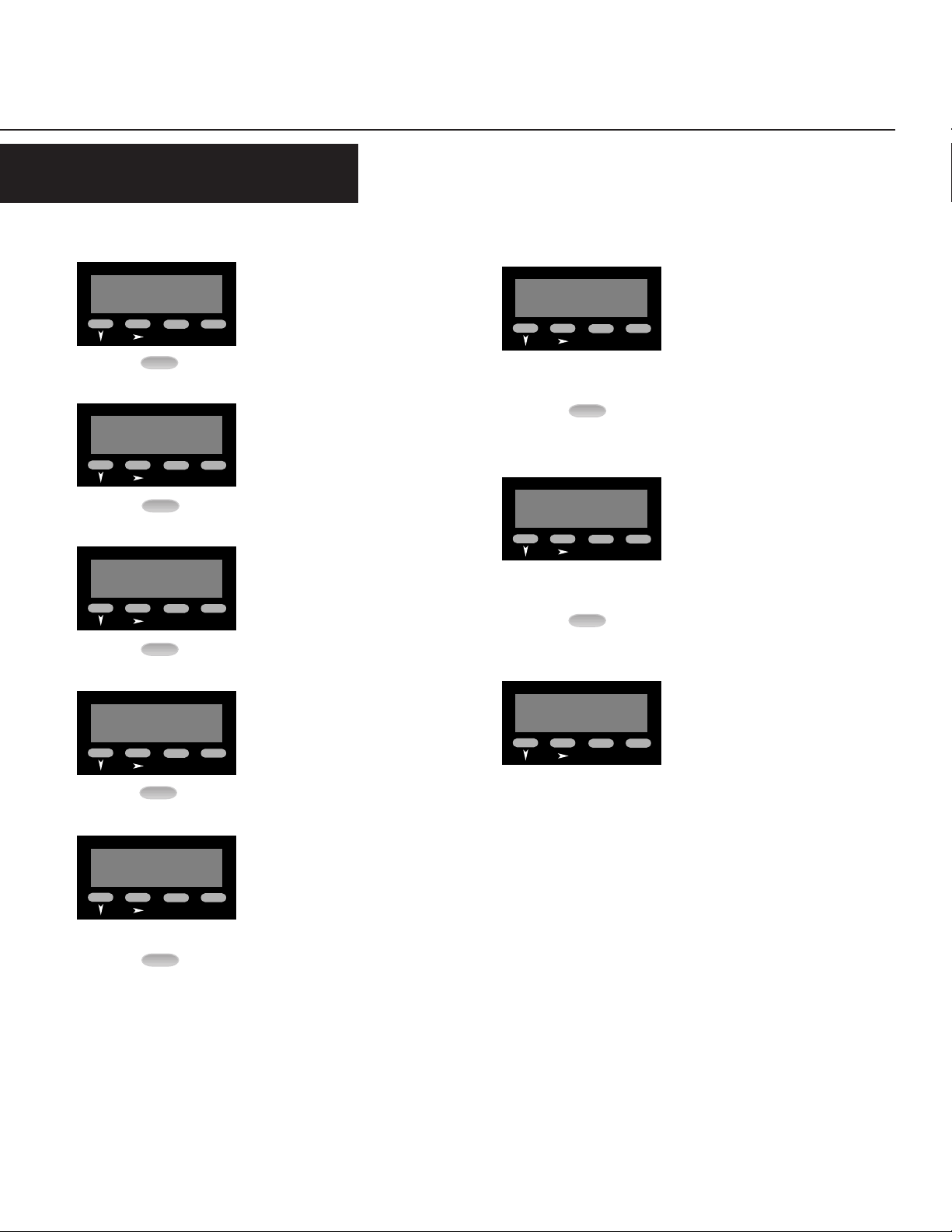
CHANGING A PRESET VALUE
Gems Sensors
Default display is the process value.
OP1
OP2
34567
RST
PGM
PGM
Gems Sensors
Proc
PGM
PGM
Gems Sensors
Hi
PGM
RST
H
RST
Pressing the Program Key will cause the
OP1
OP2
display description to appear on the
main display.* If there is no key activity
for 3 seconds, the primary display will
switch back to the process value.
Maximum (High) Value: Displays the
OP1
OP2
maximum process value the unit has
received as an input. The value can be
reset (only while being displayed) by
pressing the Reset Key.
Gems Sensors
AL 1
PGM
PGM
Gems Sensors
AL 2
PGM
PGM
2
1
RST
RST
Alarm 1 Value: Defines the process
OP1
OP2
value at or above which Alarm 1 will
activate if set to Process High Alarm in
Configuration Mode or the process value
at or below which Alarm 1 will be active
if set to Process Low Alarm in
Configuration Mode. The default value
is 100.00
Alarm 2 Value: Defines the process
OP1
OP2
value at or above which Alarm 2 will
activate if set to Process High Alarm in
Configuration Mode or the process value
at or below which Alarm 2 will be active
if set to Process Low Alarm in
Configuration Mode. The default value
is 100.00
Gems Sensors
Lo
Gems Sensors
PGM
PGM
PGM
PGM
PGM
L
RST
EEL ti
RST
Minimum (Low) Value: Displays the
OP1
OP2
minimum process value the unit has
received as an input. The value can be
reset (only while being displayed) by
pressing the Reset Key.
Alarm 1 Elapsed Time: Displays the
OP1
OP2
accumulated amount of time the alarm
1 condition was present. This value will
continue to accumulate until it is reset
by pressing the Reset Key (while the
value is being displayed). The value is
displayed in mm:ss up to 99 min 59
secs., then changes over to mmm.m
Gems Sensors
PGM
Total: Displays the total value based
OP1
OP2
upon integratation of the input signal
ttotAL
RST
using a programmable time base. The
value can be reset (only while being
displayed) by pressing the Reset Key.
* Parameter descriptions will not
appear on the primary display if the
"Help" function has been disabled.
5
Page 6

OPERATION
OPERATION MODE Continued
OTHER OPERATING DISPLAYS
Gems Sensors
OuEr
PGM
RST
Over Range Display: Appears if the
OP1
OP2
process value becomes higher than the
input full scale value.
Gems Sensors
brEA/
PGM
RST
Sensor Break Display: Appears if the
OP1
OP2
unit does not receive an input signal for
two seconds.
Gems Sensors
UndEr
PGM
RST
Under Range Display: Appears if the
OP1
OP2
process value becomes lower than the
input full scale value.
CHANGING AN ALARM VALUE
Gems Sensors
Default display is the the Process Value.
OP1
OP2
34567
RST
PGM
5 Times
PGM
Gems Sensors
AL 1
PGM
RST
From the Process Value display, scroll
OP1
OP2
through the other Operation Mode
values until Alarm 1 appears.*
Gems Sensors
PGM
Gems Sensors
190.00
PGM
1100.00
RST
1
RST
Use the Scroll Key to move from left to
OP1
OP2
right and highlight the digit that needs
to be changed. Wrap around will occur
from the least significant to the most
significant digit.
Use the Down Key to decrement the
OP1
OP2
digit until the desired value appears.
The display will wrap around from 0 to
9.
Gems Sensors
100.00
6
PGM
1
RST
To change the Alarm value, press the
OP1
OP2
Scroll Key. If there was no key activity
for 3 seconds, the Alarm value will
appear (one digit description shown on
secondary display); however, press the
Scroll Key in order to edit. The unit will
now be in Edit Operation as signified by
the most significant digit flashing.**
PGM
Gems Sensors
190.00
PGM
PGM
1
RST
After the desired digits have been
OP1
OP2
changed, press the Program Key to enter
the new value. The new value will
appear on the main display without any
flashing digits. Press the Progam Key
again and the parameter description will
appear on the main display.*
* Parameter descriptions will not
appear on the primary display if the
"Help" function has been disabled.
** Edit Operation cannot be
accessed if the Alarm Lock
has been enabled in Program
Mode.
Page 7

PROGRAMMING
PROGRAM MODE
ENTERING PROGRAM MODE AND BASIC OPERATION
The Program Mode can be accessed from the
Operation Mode by holding the Program Key
for 3 seconds.
The name of the first parameter will appear
on the primary display.*
Gems Sensors
34567
PGM
for 3 seconds
PGM
Gems Sensors
RST
ScA 1
RST
PGM
PGM
Successive presses of the Program Key will
scroll the display through the remaining
parameters in the Program Mode. To exit
Program Mode, hold the Program Key for 3
seconds.
Gems Sensors
* Parameter names will not appear on the
main display if the "Help" function has been
disabled in Program Mode.
Gems Sensors
diS 1
PGM
RST
OP1
OP2
Edit Operation
OP1
OP2
3 secs. or
PGM
Gems Sensors
0.00
PGM
1
RST
OP1
OP2
Pressing the Scroll Key or no key activity for
3 seconds will display the value for that
parameter. The secondary display will
OP1
OP2
indicate the one digit identifier for the
parameter . The digit in the secondary
display will flash to indicate the unit is in
Program Mode. If the Scroll Key was
pressed (instead of waiting 3 seconds), the
unit is in Edit Operation, as indicated by the
MSD flashing. If there had been no key
activity for 3 seconds, press the scroll key to
enter Edit Operation (MSD flashing). Use
the scroll and edit buttons to change the
value as in Operation Mode, described on
page 6. Press the Program Key to enter any
changes.
PARAMETER SEQUENCE
1
PGM
PGM
1
1
1.
ScA
diS
Scaling Point 1
Function: Sets the first sensor input value point (expressed as a % of input) which will be used in
establishing a curve for scaling sensor inputs into engineering unit values. Pressing the Reset Key will
serve as a teach function and input the sensor value currently being read
Adjustment Range: 0.00 to 100.00%
Default V alue: 0.00
Display Point 1
Function: Provides the engineering unit value that will be displayed corresponding to the sensor input value
set in the Scaling Point 1 parameter
Adjustment Range: -19999 to 99999
Default V alue: 0.00
7
Page 8

PROGRAMMING
PROGRAM MODE Continued
Scaling Point 2
2
PGM
PGM
2
2
Function: Sets the second sensor input value point (expressed as a % of input) which will be used in
establishing a curve for scaling sensor inputs into engineering unit values. Pressing the Reset Key will
serve as a teach function and input the sensor value currently being read
Adjustment Range: 0.00 to 100.00%
Default Value: 100.00
Display Point 2
2.
Function: Provides the engineering unit value that will be displayed corresponding to the sensor input value
set in the Scaling Point 2 parameter
Adjustment Range: -19999 to 99999
Default Value: 100.00
ScA
diS
The scaling process can be repeated up to a total of 10 scale and display points.
Scale and display points will continue to be offered (up to 10 total) so long as 100.00 (the maximum adjustment range) has
not been selected as a scaling point value.
Application Example
Programming Scale and Display Points
Situation: The number of gallons contained in a cylindrical
tank with vertical sides is linearly related to the surface level.
The desired range of levels in the tank is 0 gallons minimum
and 400 gallons maximum. A 4-20 mA sensor is used to
indicate liquid level (the sensor provides a changing current
as the level changes). When the liquid level is at the 0 gallon
minimum, the sensor outputs 4 mA, and when the liquid level
is at the 400 gallon maximum, the sensor outputs 20 mA.
Parameter Entries:
Configuration Mode: Input - Select "2300"
Program Mode: Decimal Point - Select 0.00
Scaling Point 1: 0.00 (= 0% which corresponds to the 4 mA level)
Display Point 1: 0.00 (= 400 gallons which corresponds with Scaling Point 1)
Scaling Point 2: 100.00 (= 100% which corresponds to the 20 mA level)
Display Point 2: 400.00 (= 5 gallons which corresponds with Scaling Point 2)
400 GAL
200 GAL
0 GAL
➙
➙
20 FT
10 FT
➙
0 GAL
(4 mA)
(12 mA)
200 GAL
(20 mA)
400 GAL
Result: As the sensor output changes from 4 mA to 20 mA, the display will linearly read from 0 to 400.00 - indicating the amount of liquid in
the tank at any given moment. If under no load the meter does not read exactly zero, enter a process variable offset (Program Mode) value.
For example: Meter reads "3.2" enter "-3.2".
8
Page 9

PROGRAMMING
PROGRAM MODE Continued
dEc
PGM
rt
rt
Lo
PGM
Hi
PGM
P
Decimal Position
d
L
H
Function: Sets the position of the decimal point for use in displaying the process and alarm values
Adjustment Range: 0 to 0.000
Default Setting: 0.00
Retransmission Scale Minimum
Configuration mode)
Function: Defines the lower end of the linear scale for the retransmission output by defining the value equated
to the minimum output signal
Adjustment Range: -19999 to 99999
Default V alue: 0.00
Retransmission Scale Maximum
Configuration mode)
Function: Defines the upper end of the linear scale for the retransmission output by defining the value equated
to the maximum output signal
Adjustment Range: -19999 to 99999
Default V alue: 100.00
(Appears only if a retransmission output has been enabled in
(Appears only if a retransmission output has been enabled in
oFF
PGM
Filt
PGM
Process Variable Offset
O
F
Function: Corrects a known offset of the input in order to more accurately display the process value
Adjustment Range: -19999 to 99999
Default V alue: 0.00
Input Filter Time
Function: Filters the input over a user definable time period to minimize the effect on the Process Value of
any extraneous impulses
Adjustment Range: 0.0 (Off) to 100.0
Default V alue: 2.0
9
Page 10

PROGRAMMING
PROGRAM MODE Continued
Display Color Change
Color
o
Function: Defines the color of the display for prior to and after the preset value is reached
Adjustment Range:
PGM
Loc/
PGM
HELP
rEd
Red: The display will
always be red
Default Value: Gr een to Red
Alarm Lock
/
h
Function: Determines whether the Alarm Values can be changed via the front panel
Adjustment Range:
En
Enable: Alarm values are read only
Default Value: Disable
Help Prompt
Function: Determines whether the multi-character parameter name will appear on the main display for 3
seconds prior to the parameter value appearing
Adjustment Range:
GrEEn
Green: The display will
always be green
Gn_rd rd_Gn
Green to Red: The
display will be green
when no alarm condition
is present. It will turn
red when either alarm is
active
Disabled: Alarm values can be viewed and changed.
Red to Green: The
display will be red when
no alarm condition is
present. It will turn green
when either alarm is
active
diS
10
HLP
Help - Yes: Multi-character parameter descriptions will
appear on the primary display. The value associated
with that parameter will appear by pressing the scroll
key or waiting for 3 seconds
Default V alue: Help - Yes
Y
Help - No: Only the parameter values will appear on the
primary display. The parameter can be identified by a
single digit in the secondary display
HLP
N
Page 11

CONFIGURATION
CONFIGURATION MODE
ENTERING CONFIGURATION MODE AND BASIC OPERATION
The Configuration Mode can be accessed
from the Operation Mode by holding the
Down and Program Keys for 3 seconds.
To exit do the same.
The name of the first parameter will appear
on the primary display.*
Gems Sensors
34567
PGM
PGM
Gems Sensors
OP1
OP2
RST
for 3 seconds
OP1
OP2
1nPut
RST
PGM
PGM
Successive presses of the Program Key will
scroll the display through the remaining
parameters in the Configuration Mode. To
exit Configuration Mode, hold the Down and
Program Keys for 3 seconds.
* Parameter names will not appear on the
main display if the "Help" function has been
disabled in Program Mode.
Gems Sensors
FrEQ
PGM
RST
OP1
OP2
3 secs. or
PGM
Edit Operation
Gems Sensors
2300
PGM
i
RST
OP1
OP2
Pressing the Scroll Key or no key activity for
3 seconds will display the value for that
parameter. The secondary display will
indicate the one digit identifier for the
parameter . The digit in the secondary
display will flash to indicate the unit is in
Configuration Mode. If the Scroll Key was
pressed (instead of waiting 3 seconds), the
unit is in Edit Operation, as indicated by the
MSD flashing. If there had been no key
activity for 3 seconds, press the scroll key to
enter Edit Operation (MSD flashing). Use
the scroll and edit buttons to change the
value as in Operation Mode, described on
page 6. Press the Program Key to enter any
changes.
PARAMETER SEQUENCE
1nPut
PGM
i
Input Range
Function: Selects the DC input range
Adjustment Range:
2200
2300
0-20 mA 4-20 mA 10-50 mA 0-5 Volts DC
3400
0-10 V olts DC
3500
2-10 V olts DC ±100 mV ±1 V olts DC
2400
2900
3200
3100
3300
1-5 V olts DC
3600
±10 V olts DC
11
Page 12

CONFIGURATION
CONFIGURATION MODE Continued
Frequency
FrEQ
PGM
AL
1
1
Function: AC Power Supply frequency for the meter.
Adjustment Range:
Alarm 1 Type
Function: Sets the action of the alarm to one of the following choices:
Adjustment Range:
6050
AL
PGM
2
PGM
P_Hi
Process High: Alarm will
activate when the process
value equals or exceeds
the Alarm 1 setting
Default V alue: Process High Alarm
Alarm 2 Type
2
Function: Sets the action of the alarm to one of the following choices:
Adjustment Range:
P_Hi
Process High: Alarm will
activate when the process
value equals or exceeds
the Alarm 2 setting
Default V alue: No Alarm
P_Lo
Process Low: Alarm will
activate when the process
value equals or is less
than the Alarm 1 setting
P_Lo
Process Low: Alarm will
activate when the process
value equals or is less
than the Alarm 2 setting
nonE
No Alarm: Alarm 1 will
be inactive
nonE
No Alarm: Alarm 2 will
be inactive
12
Page 13

CONFIGURATION
CONFIGURATION MODE Continued
Output 1 Usage
Out
1
U
Function: Determines how the transistor and relay for output 1 will operate
Adjustment Range:
Out
PGM
2
A1nd
Alarm 1, Non latching,
Direct Action: The output
will be On when Alarm 1
is active, and turn Off
once the Alarm 1
condition is no longer
present
012d
Logical OR of Alarm 1 & 2,
Direct Action: The output
will be On when a logical
OR condition between
Alarm 1 and Alarm 2 is
present
Default V alue: Alarm 1, Non latching, Direct Action
Output 2 Usage
u
Function: Determines how the transistor and relay for output 2 will operate
Adjustment Range:
A1nr
Alarm 1, Non latching,
Reverse Action: The
output will be On when
Alarm 1 is inactive, and
turn Off when the Alarm
1 condition is present
012r
Logical OR of Alarm 1 &
2, Reverse Action: The
output will be Off when
a logical OR condition
between Alarm 1and
Alarm 2 is present
A1Ld
Alarm 1, Latching, Direct
Action: The output will be
On when Alarm 1 is
active, and turn Off only
when reset via the front
panel
Alarm 1, Latching,
Reverse Action: The
output will be Off when
Alarm 1 is active, and
turn On only when reset
via the front panel
A1Lr
PGM
A2_d
Alarm 2, Direct Action:
The output will be On
when Alarm 2 is active,
and turn Off once the
Alarm 2 condition is no
longer present
Default V alue: Alarm 2, Direct Action
A2_r
Alarm 2, Reverse Action:
The output will be On
when Alarm 2 is inactive,
and turn Off when the
Alarm 2 condition is
present
012d
Logical OR of Alarm 1 & 2,
Direct Action: The output
will be On when a logical
OR condition between
Alarm 1 and Alarm 2 is
present
Logical OR of Alarm 1 &
2, Reverse Action: The
output will be Off when
a logical OR condition
between Alarm 1and
Alarm 2 is present
012r
13
Page 14

CONFIGURATION
CONFIGURATION MODE Continued
Retransmission Output
rt
En
t
Function: Selects the range of the retransmission output
Adjustment Range:
PGM
OPtn
tot
nonE
None
Default Value: None
Option Selection
o
t
Function: Determines the function of the board installed in the option slot
Adjustment Range:
nonE
No Input Security: When the
Default V alue: None
Totalizer Scale Factor
Function: Sets the time base used for the totalization calculation. This value should be set the
same as the time base used for the engineering units which appear on the display. Ex: If the
display is calibrated to display GPM, set the Totalizer scale factor to minutes
Adjustment Range:
0-5u
0-5 V olts DC
0-20A
0-20 mA
SctY
digital input is active, the
Program and
Configuration Modes
cannot be accessed
1-5u
1-5 Volts DC
4-20A
4-20 mA
tArE
Tare: When the digital
input is activated the
currently measured value
is zeroed out and will
remain as a constant
offset
0-10u
0-10 V olts DC
2-10u
2-10 Volts DC
14
SEc
Seconds
Default Value: Seconds
<>in
hr
HoursMinutes
Page 15

APPENDIX A
SPECIFICATIONS
Process Input
Range: To 50 mA, ±10 Volts DC, ±100 mV
Accuracy: + 0.01% of span
Sample Rate: 100 ms
Resolution: 14 bits
Sensor Break: Detected within 2 seconds
Control Inputs
Type: Sourcing, Edge Sensitive
Logic: Low < 2.0 VDC, High > 3.0
Impedance: 4.7 KΩ to +Voltage - Sourcing
Response Time: 25 ms
Function: Programmable
Outputs
Solid State: NPN open collector, 30 VDC max, 100 mA max.
Relay: SPDT, 5A resistive @ 110VAC
Latency: 75 µ seconds, plus 8 ms for relay pull-in
Linear Outputs
Ranges: 0-20mA, 4-20mA, 0-10V, 2-10V, 0-5V, 1-5V
Accuracy: ±0.25% (mA at 250Ω, V at 2kΩ);
degrades linearly to ±0.5%
Resolution: 8 bits in 250ms (10 bits in 1s typ.)
Update: Approximately 4/s
Load Impedence: mA Ranges: 500Ω max.; V Ranges: 500Ω min.
Electrical
Supply Voltage: 90-264 VAC, 50/60 Hz, or 20-50 VAC/VDC
Power Consumption: 4 Watts
Access. Power Supply:24 VDC @ 30 mA
Display
Type: Red/Green, 7 segment LED, 5 digits primary
Height: 0.71" (18mm) primary display,
Annunciators: Output 1 & 2 status
Physical
Dimensions: 48mm x 96mm, 110mm deep
Mounting: Panel mount (mounting bracket supplied),
Terminals: Screw type - combination head
Front Panel Rating: NEMA 4X/IEC IP65
Case Material: GE Lexan 940
Weight: 0.56 lbs.
Environmental
Operating Temp.: 0° to 55° Celsius, 32° to 131° Fahrenheit
Storgage Temp.: -20° to 80° Celsius, -4° to 176 ° Fahrenheit
Relative Humidity: 20% to 95% non-condensing
display, single digit secondary display
0.3" (7mm) secondary display
45mm x 92mm cutout
Approvals
General: CE
EMC Susceptibility: Complies with EN50082-1: 1992,
EN50082-1, 1995
EMC Emissions: Complies with EN50081-1: 1992,
EN50081-2: 1994
Safety: Complies with EN61010-1: 1993
15
Page 16

GENERAL
ORDERING INFORMATION
DM28 - 2
2nd Relay Option
0 None
1 2nd Relay
Power Supply
0 90-264 VAC
2 20-50 VAC/VDC
Linear Output
Option
0 None
3 Linear Output
Serial Communication
Option
0 None
6 Digital Input
WARRANTY
Gems Sensors Inc., the seller, warrants its products to be free from defects in material and workmanship in normal use and service for a
period of one year from date of shipment. Gems reserves the right and option to refund the purchase price in lieu of repari or
replacement upon evaluation of the returned original part. Modification, misuse, attempted repair by others, improper installation or
operaiton shall render this guarantee null and void. Gems Sensors Inc. makes no warranty of merchantability or fitness for a part or
purpose.
Limits of Liability
In no circumstances shall Gems Sensors Inc. be liable for special, consequential or exemplary damages of any kind or character,
including contract tort, and strictly liability in tort and contract.
Equipment sold by Gems Sensors Inc. is not intended for use in a nuclear installation, nor shall it be used as a “Basic Component” as
same as deined under Part 21, Title 10 of the Code of Federal Regulations. In the event of such use, you agree to indemnify and hold us
harmless from any and all subsequent liabilities and responsibilities which might arise in connection with such use.
Returning Goods
Contact your local sales agent or the factories for return policy prior to sending back any product.
16
#182016
Revision: none
Gems Sensors Ltd.
Lennox Road
Basingstoke
Hants, RG22 4AW
Phone: +44 (0) 1256.320244
Fax: +44 (0) 1256.473680
Gems Sensors Inc.
1 Cowles Road
Plainville, CT 06062
USA
Phone: +001 (1) 860.747.3000
Fax: +001 (1) 860.747.4244
 Loading...