

Page 1
Form 159Form 159
Form 159
Form 159Form 159
Sheet P/N 7800447Sheet P/N 7800447
Sheet P/N 7800447
Sheet P/N 7800447Sheet P/N 7800447
RevRev
. C. C
Rev
. C
RevRev
. C. C
®®
®
WW
arrickarrick
W
arrick
WW
arrickarrick
®®
Direct Current Controls Series Direct Current Controls Series
Direct Current Controls Series
Direct Current Controls Series Direct Current Controls Series
Installation and Operation BulletinInstallation and Operation Bulletin
Installation and Operation Bulletin
Installation and Operation BulletinInstallation and Operation Bulletin
This bulletin should be used by experienced personnel as a guide to the installation of Series Direct Current
Controls. Selection or installation of equipment should always be accompanied by competent technical assistance.
We encourage y ou to contact Gems Sensors or its local representative if further information is required.
Installation
1. Remove the plug-in module from the octal base. When plug-module is removed, the pin number identification can
be see on the octal base.
2. Mount the octal socket (base) on a rigid vertical or horizontal surface using two #6 or #8 screws. The controls
should be mounted within an enclosure of proper NEMA integrity.
3. After the base has been mounted, refer to the applicable wiring diagram. Connect the electrodes to the designated
terminals of the socket using #14-#18 AWG wire for interconnecting leads. Be sure that the control is wired in
accordance with the appropriate application drawing.
4. Wire the appropriate load contact in series with the “Hot” lead of the load device. Note: Load current rating must
not exceed the maximum rating of the relay contact.
5. In accordance with the proper wiring diagram, connect the negative side (-) of the power supply to terminal #1 of
the octal socket and the positive side (+) of the supply to terminal #2 of the socket. Verify that the power supply
output voltage correlates to the data label on the control. Caution: Reversal of power supply leads from desig-
nated polarity may damage the internal solid-state circuitry of the control. Verify the correct polarity of the
power supply connections before proceeding to step #6.
6. Plug the DC level control into the octal socket. Numbers at the base of the pins match the numbers on the installed
base. The control is keyed for proper installation; the unit will not plug in if the pins are not properly aligned.
Warrick Controls recommends that you inspect and clean the electrode rods annually.
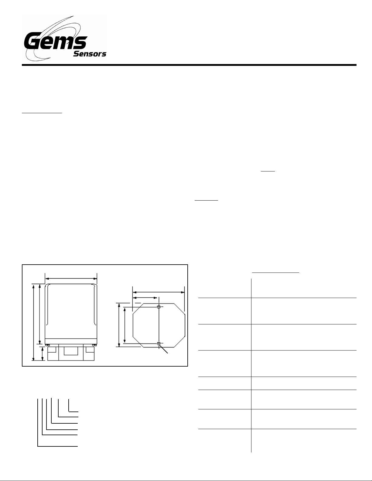
Dimensional Diagram
2-3/8 in
2-5/16 in
1-5/32 in
2-3/4 in
3-1/2 in
5/8 in
2.0 in
1-11/16 in
11/64 in dia
Use copper (60/70° C) wire only. Torque to 20 inch pounds.
DC XXXX XX XXDC XXXX XX XX
DC XXXX XX XX
DC XXXX XX XXDC XXXX XX XX
Time Delay: (decreasing level 1-30 sec)
Time Delay: (increasing level 1-30 sec)
Enclosure:
Mode:
Sensitivity (ohms):
EE
E- 1M
EE
Supply Voltage:
00
0- none,
00
DD
D- direct,
DD
11
1- NEMA 1,
11
II
I- inverse
II
BB
B- 22K,
BB
11
1- 12 VDC,
11
44
4- NEMA 4
44
C C
C- 100K,
C C
22
2- 24 VDC
22
DD
D- 470K,
DD
Contact Design:
Contact Ratings:
Contact Life:
Electronics
Module:
Supply Voltage
Supply Current:
Sensitivity Range:
Temperature
Range:
Specifications
SPDT (1 form C) 1 Normally Open
(N.O.) and 1 Normally Closed (N.C.)
5A @ 30 VDC or 120 VAC, 4A @ 240
VAC resistive, 1/8th Hp 120 VAC, 240
VAC pilot duty code C150
Mechanical - 20 million operations.
Electrical - 100,000 operations minimum @ rated load
Solid-state components epoxy sealed
in a black polystyrene plug-in style
housing
12 or 24 VDC - Negative ground, ±20%
12 VDC Model - Relay de-energized
10mA, Relay energized 40mA
0-1M maximum specific resistance,
ohm factory set
-50° to +150° F
Page 2
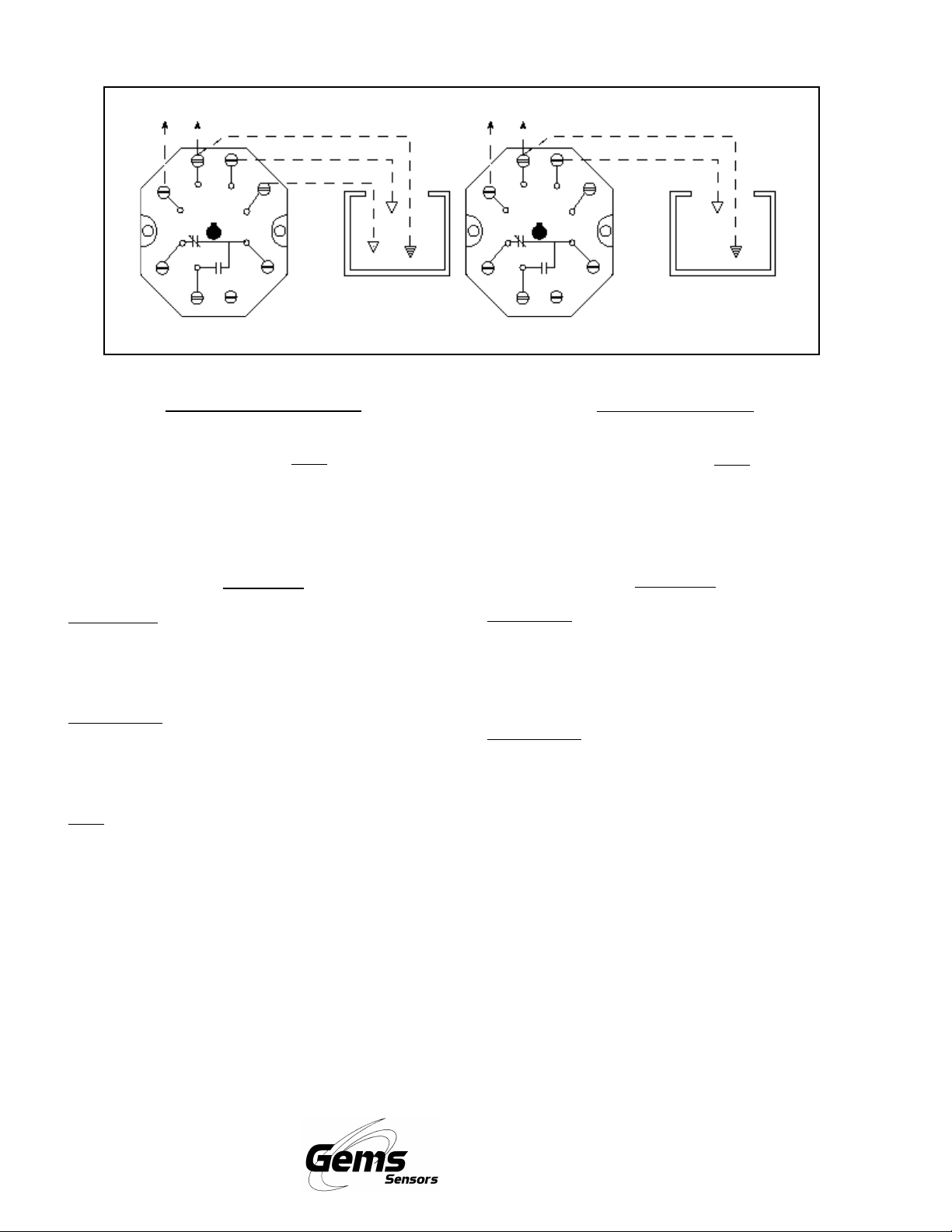
Wiring Diagram
DC Power
Reference Probe
High Probe
H
8
1
2
3
4
NC
NO
Differential Level WDifferential Level W
Differential Level W
Differential Level WDifferential Level W
6
7
Low Probe
L
C
If metallic, tank may
be used instead of
reference probe
iringiring
iring
iringiring
Connect negative side (-) of VDC supply line to terminal #1
and positive (+) side to terminal #2.
Note Note
Note: Check polarity of
Note Note
power connections. Connect terminal #8 (H) to the high
electrode and terminal #7 (L) to the low electrode. Terminal #1
can be grounded to tank if the tank is metallic. When the tank
is not metallic, terminal #1 must be connected to an additional
electrode of length equal to or longer than the longest probe.
DC Power
Reference Probe
High Probe
H
8
1
2
3
4
NC
NO
L
7
6
C
Single Level WSingle Level W
Single Level W
Single Level WSingle Level W
If metallic, tank may
be used instead of
reference probe
iringiring
iring
iringiring
Connect negative side (-) of VDC supply line to terminal #1
and positive side (+) to terminal #2.
Note:Note:
Note: Check polarity of
Note:Note:
power connections. Connect terminal #8 (H) to the electrode. Terminal #1 can be grounded to tank if the tank is
metallic. When the tank is not metallic, terminal #1 must be
connected to an additional electrode of length equal to or
longer than the longest probe.
OperationOperation
Operation
OperationOperation
Direct Mode: Direct Mode:
Direct Mode: The control energizes closing load contact 4-6
Direct Mode: Direct Mode:
and opening load contact 3-6 when the level rises to the short
electrode connected to terminal #8. The control remains
energized until the level recedes below the long electrode
connected to terminal #7.
Inverse Mode:Inverse Mode:
Inverse Mode: The control de-energizes opening load
Inverse Mode:Inverse Mode:
contact 4-6 and closing load contact 3-6 when the level rises
to the short electrode connected to terminal #8. The control
remains de-energized until the level recedes below the long
electrode connected to terminal #7.
Note:Note:
Note: For single level service controls utilizing both increas-
Note:Note:
ing and decreasing time delays, a jumper wire is required
between terminals #7 and 8.
OperationOperation
Operation
OperationOperation
Direct Mode:Direct Mode:
Direct Mode: The control energizes closing load contact 4-
Direct Mode:Direct Mode:
6 and opening contact 3-6 when the level rises to the
electrode connected to terminal #8. The control deenergizes and the contacts return to their de-energized state
when the level recedes below the electrode connected to
terminal #8.
Inverse Mode:Inverse Mode:
Inverse Mode: The control de-energizes opening load
Inverse Mode:Inverse Mode:
contacts 4-6 and closing load contact 3-6 when the level
rises to the electrode connected to terminal #8. The control
energizes and the contacts return to the energized state
when the level recedes below the electrode connected to
terminal #8.
Gems Sensors Inc.
One Cowles Road
Plainville, CT 06062-1198
Tel: 860-793-4579
Fax: 860-793-4580
 Loading...