


Form 237
Sheet P/N 7801165
Warrick
®
Rev. D
Series M Mechanical Tilt Float Switch
Installation and Operation Bulletin
Specifications
Cord
Contact Rating
Contact Design
Temperature Rating
Overall Weight
Tether Method
Approvals
Installation
Tether Tie-Wrap (Fig 1)
Attach cord, using a tie-wrap, to a stationary structure. This is known as the tether point, it will determine the pumping range.
The farther the float is placed from the tether point, the greater the pumping range. The minimum distance that the float should
be placed from the tether point is 3 inches.
16 gauge, 2 or 3 conductor SJOW, Oil Resistant CPE
13 amp @ 120/240 VAC, 1/2hp
SPST, Normally Open or Normally Closed, Common with N.O. & N.C. (Form C)
32°F (0°C) to 194°F (90°C) Dry and 140°F (60°C) Water Resistant
1.0 lbs. (not including weight)
Tie-wrap nylon, weight: 2.5 lbs.
U.L. Recognized, CSA Certified
Tether-Weight (Fig 2)
Place tension-brand over the cord before installation. Place the weight at the desired position and secure with the tension-band.
This position will determine the pumping range. The farther the float is placed from the tether point, the greater the pumping
range. The minimum distance that the float should be placed from the tether point is 3 inches.
Determine tether point using charts below as a reference
Notes:
1. To Prevent Motor Burnout - In a
Tie-Wrap
Tether
Point
Tether
Point
pumpdown application make sure the turnoff level is at least 2 inches above the in-
Weight
take of the submersible pump.
Pumping
Range
2. Securing Tether Points - Make sure lev-
Tie-Wrap
Pumping
Range
els are correct and that floats are free from
any obstructions before securing tether
points.
Figure 2
Tether Data For Wide Angle Float
18
16
14
12
10
8
6
Approx Pumping Range, Inches
5 6 7 8 9 10 11 12
Tether Length, Inches
Figure 1
Tether Data For Narrow Angle Float
8
6
4
2
Approx Pumping Range, Inches
3 4 5 6 7 8 9 10
Tether Length, Inches
Notes:
1. Narrow angle pumping range is approximately 2 In. to 8 In.
2. Wide angle pumping range is approximately 5 In. to 18 In.
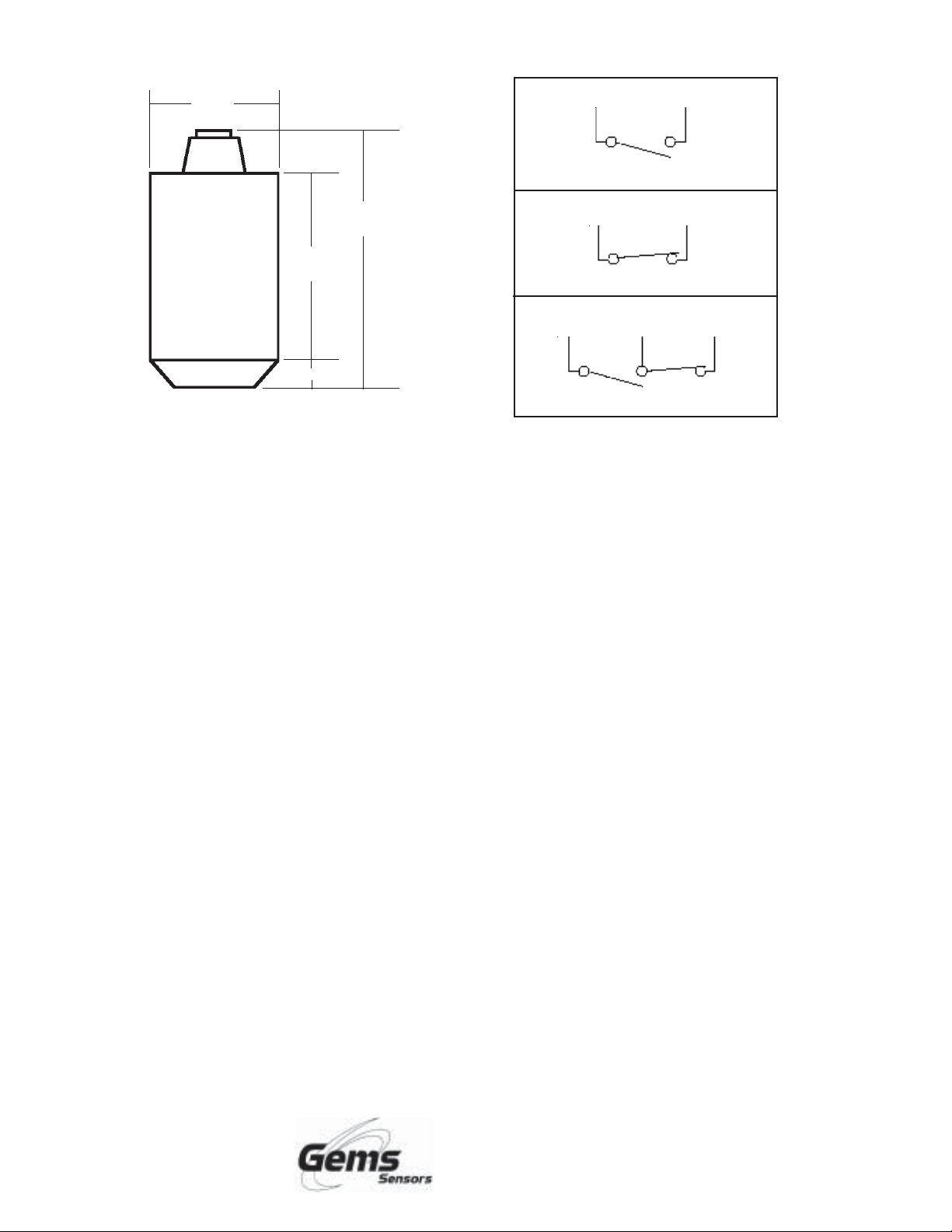
Dimensions
Contact Configurations
2-3/8”
(6.03 cm)
4-5/8”
(11.75 cm)
3-3/8”
(8.57 cm)
1/2” (127 cm)
White Black
N.O.
White Black
N.C.
Red Black White
S.P.D.T.
Important Points:
• Gems products must be maintained and installed in strict accordance with the National Electrical Code and the applicable
Gems Product Instruction Bulletin that covers installation, operation and proper maintenance. Failure to observe this
information may result in serious injury or damages.
• For hazardous area applications involving such things as, but not limited to, ignitable mixtures, combustible dust and
flammable materials, use an appropriate explosionproof enclosure or intrinsically safe interface device.
• Please adhere to the pressure and temperature limitations shown throughout this catalog for our level and flow sensors.
These limitations must not be exceeded. These pressures and temperatures take into consideration possible system surge
pressures/temperatures and their frequencies.
• Selection of materials for compatibility with the media is critical to the life and operation of Gems products. Take care in the
proper selection of materials of construction, testing is required.
• NSF-approved sensors are made of materials approved for potable water applica tions according to Standard 61.
• Stainless steel is generally regarded as safe by NSF and FDA.
• Life expectancy of switch contacts varies with application. Contact Gems if life cycle testing is required.
• Ambient temperature changes do affect switch set points, since the gravity of a liquid can vary with temperature.
• Our sensors have been designed to resist shock and vibration. However, shock and vibration should be minimized.
• Filter liquid media containing particulate and/or debris to ensure the proper operation of our products.
• Electrical entries and mounting points in an enclosed tank may require liquid/vapor sealing.
• Our sensors must not be field-repaired.
• Physical damage sustained by product may render it unserviceable.
Return Policy
Returns are accepted on stock items up to 30 days from date of order. You must
contact our Returns Department for a Return Authorization (RA) number. Return
the goods - freight prepaid - in the original container and include original packing
slip. C. O. D. returns are not accepted. Gems reserves the right to apply
restocking charges.
Tel: 860-793-4357
Fax: 860-793-4563
Gems Sensors Inc.
One Cowles Road
Plainville, CT 06062-1198
Tel: 860-793-4579
Fax: 860-793-4580
 Loading...