

Page 1
Technical Documentation
Edition: 11-2010
Version: 1
Article no.: 233571
Gems Sensors & Controls One Cowles Rd Plainville CT Telephone 800-378-1600
XT-1000
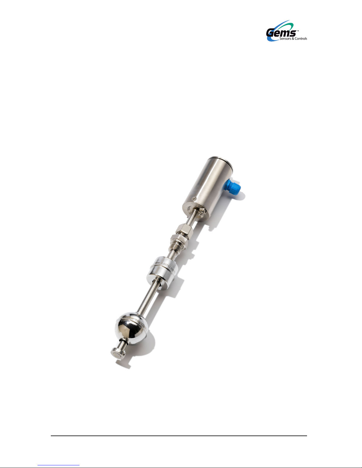
The magnetostrictive level sensor
Page 2

Page 2/19 XT-1000
Page 3

XT-1000 Page 3/19
Table of contents
1 Properties.........................................................................................................4
2 Safety instructions...........................................................................................5
3 Design and mode of operation ......................................................................6
4 Installation .......................................................................................................8
4.1 Installation with screw-in unit......................................................................................... 9
4.2 Installation with flange.................................................................................................10
4.3 Installation on the bypass ............................................................................................. 10
5 Electrical connection......................................................................................12
6 User configuration.........................................................................................14
6.1 Measuring span at the level sensor...............................................................................14
6.2 Current consumption in failure mode...........................................................................16
7 Technical data ................................................................................................17
7.1 Sensor.......................................................................................................................... 17
7.2 Floats ........................................................................................................................... 19
© Copyright:
Reproduction and translation only with the written consent of GEMS Sensors & Controls.
GEMS Sensors & Controls reserves the right to carry out product alterations without prior notice.
Page 4

Page 4/19 XT-1000
1 Properties
The high-precision and robust XT-1000 level sensor is designed to provide continuous
gauging of liquid media levels in tanks. The measuring principle used by the sensor
exploits the physical effect of magnetostriction and is largely unaffected by temperature.
Magnetostriction is particularly ideal where level measurements are required to be
extremely accurate, e.g. in the chemical industry.
The level sensor outputs measuring signals in the range 4 to 20 mA. Available in lengths
of 8” to 19’ it is compatible with a variety of tank dimensions. It also comes in the
following versions:
Version for installation on a bypass with magnetic float
Version with flange
Version with screw-in unit for infinitely variable positioning of the level sensor
The Ex-approved version of the level sensor can be installed in potentially explosive
atmospheres in which electrical equipment of category 1 (zone 0) or category 1/2
(zone 0/1) are required.
Operating on the digital HART protocol, the XT-1000 HART level sensor is able to output
the position of the first, second or both floats (refer to the XT-1000 HART documentation).
Page 5
XT-1000 Page 5/19
2 Safety instructions
The purpose of the XT-1000 level sensor is to gauge liquid levels in tanks. Use the level
sensor for this purpose only. The manufacturer accepts no liability for any form of
damage resulting from improper use!
The level sensor has been developed, manufactured and tested in accordance with stateof-the-art technology and with recognized safety rules and regulations. Nevertheless,
hazards may arise from its use. For this reason, the following safety information must be
observed:
Do not change or modify the level sensor or add any equipment without the prior
consent of the manufacturer.
The installation, operation and maintenance of the level sensor must be carried out only
by expert, authorized personnel. Specialized knowledge must be obtained by undergoing
regular training.
Operators, installers and service technicians must comply with all applicable safety
regulations. This also applies to any local safety regulations and accident prevention
regulations which are not stated in these operating instructions.
The safety instructions in this manual are labelled as follows:
Failure to observe these safety instructions will result in a risk of
an accident or of damage to the XT-1000 level sensor.
Useful information designed to ensure continued and correct operation
of the XT-1000 level sensor or helpful advice to make your work easier.
Page 6
Page 6/19 XT-1000
3 Design and mode of operation
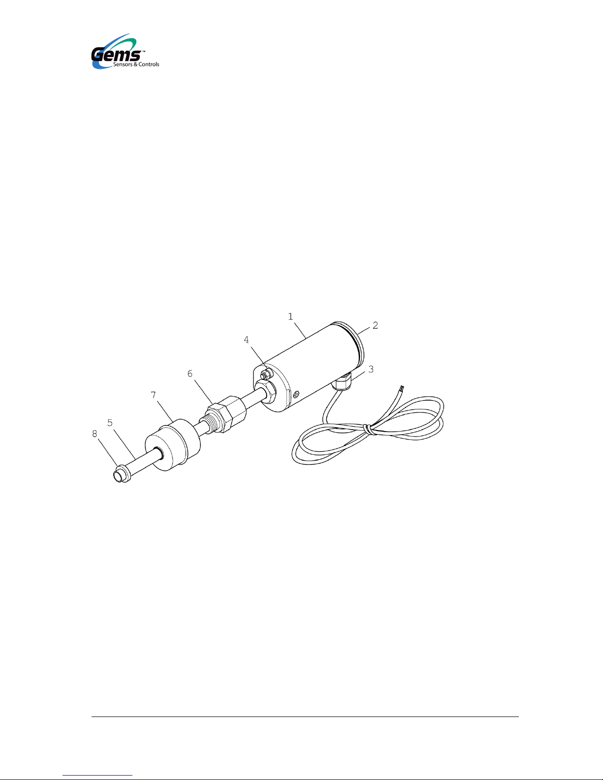
The design of the XT-1000 level sensor has been illustrated using the version with screwin unit (see Figure 1).
Inside sensor head (1) of the level sensor, concealed by cap (2), are the protected terminal
clamps and configuration buttons. The electrical connection is established by an
M16 x 1.5 screwed cable gland (3) or M12 plug-in connection at the top of the sensor
head and by ground connector (4) at the bottom of the sensor head (see “Installation”
and “User configuration”).
Probe tube (5) features a screw-in unit (6) (cutting ring or sealing gland coupling) for
height adjustment capability or a flange (not shown) for fixed installation. Float (7) is the
key component for continuous gauging of the product filling level or boundary layer and
is held on the probe tube by a collar (8).
The XT-1000 B version is supplied without a process connection and float.
Figure 1: XT-1000 level sensor
Page 7
XT-1000 Page 7/19
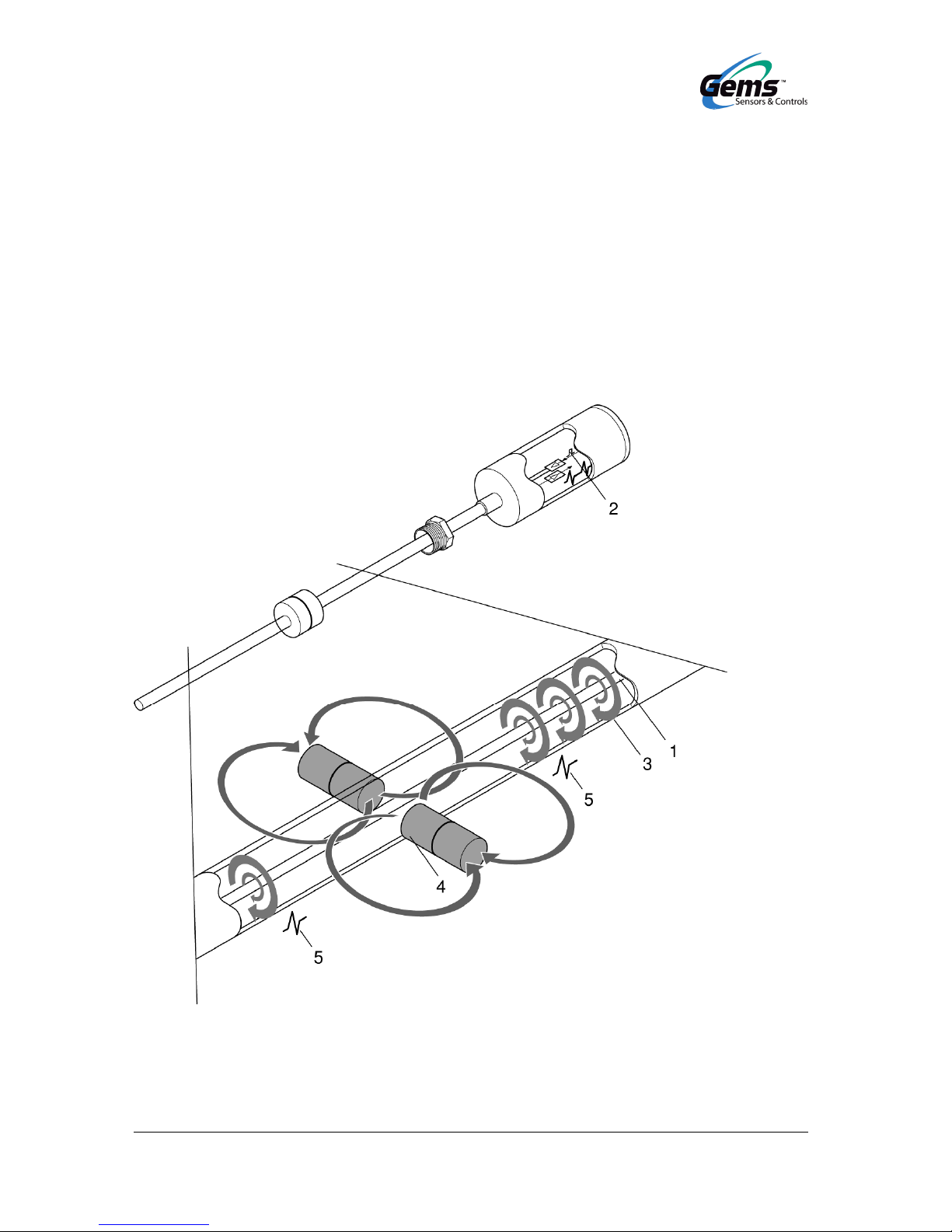
The measuring principle illustrated in Figure 2 exploits the physical effect of magnetostriction and is largely unaffected by temperature. The probe tube contains a tensioned wire
(1) made of magnetostrictive material. The sensor electronics transmit current pulses (2)
through the wire, which generate a circular magnetic field (3). A magnet (4) contained in
the float acts as the level sensor. Its magnetic field applies an axial magnetic field to the
wire. The superposition of the two magnetic fields produces a torsional wave (5) at the
float position, which then propagates along the wire in both directions. One wave
propagates directly to the sensor head, the other propagates down to the bottom of the
probe tube and is reflected. The time between the current pulse being transmitted and
the wave arriving at the sensor head is measured. From these propagation times, it is
possible to determine the current position of the float.
Figure 2: operating principle of the XT-1000 level sensor
Page 8
Page 8/19 XT-1000
4 Installation
This product should not be installed in a potentially explosive
application.
Also observe any local safety regulations and accident prevention
regulations which are not stated in these operating instructions.
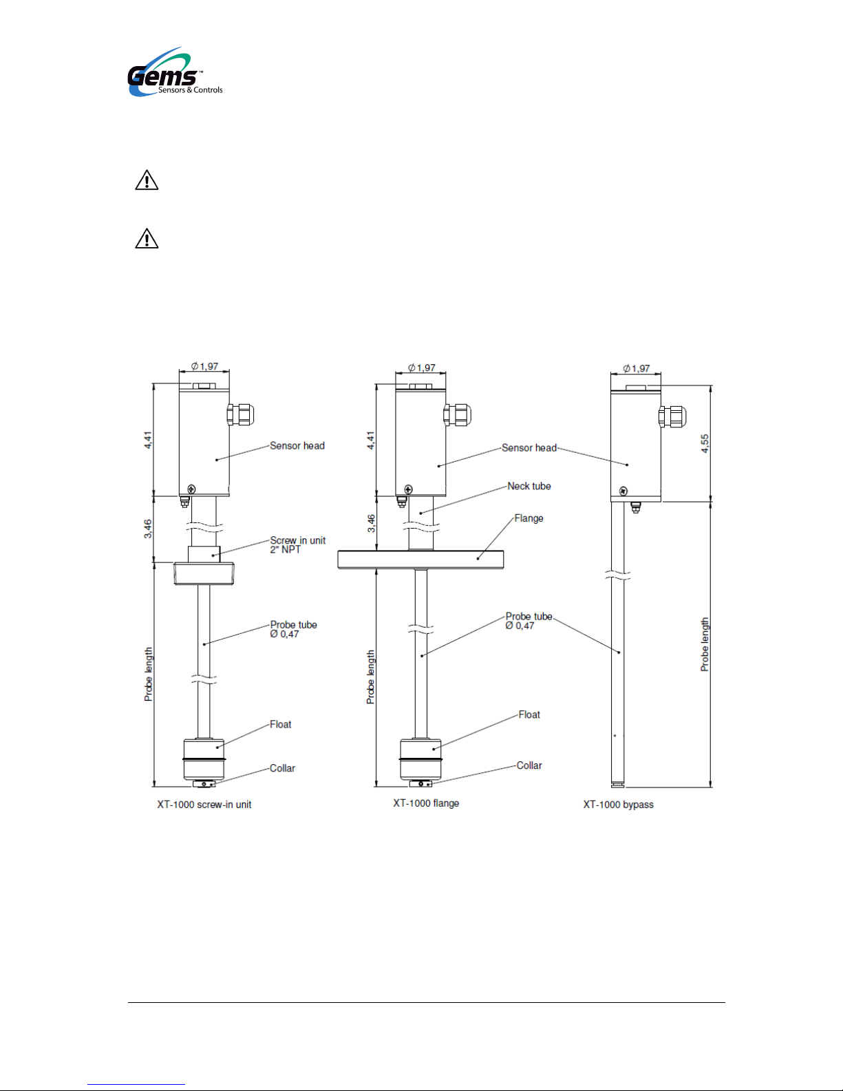
This section describes how to install the level sensor. The procedures for each version are
described separately (see Figure 3).
Figure 3: XT-1000 versions
Page 9
XT-1000 Page 9/19
During installation, take great care not to bend the probe tube,
and protect the float from shock and impact loads.
Installing a level sensor in areas exposed to a powerful external magnetic
field is not recommended because this could impair gauging.
The level sensor can also be fitted into the tank from underneath.
If the float is removed during installation, it must be slid back onto the
probe tube afterwards with the “TOP” marking oriented towards the
sensor head end, to enable correct measurements to be made.
4.1 Installation with screw-in unit
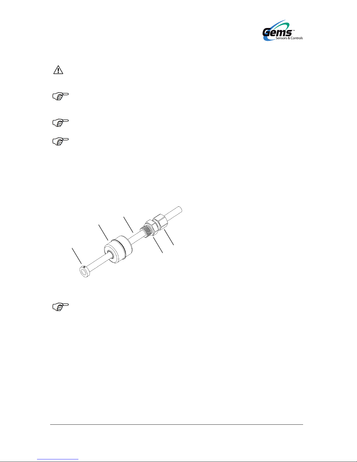
Figure 4: installation with screw-in unit
Removal of the float is necessary only if the float does not fit through the
installation opening in the tank. Otherwise, please proceed directly to
steps 3, 6 and, if applicable, 7.
Insert the level sensor into the tank (see Figure 4):
(1) Loosen both set screws, remove collar (1) and remove float (2) from probe tube (3).
(2) If necessary, slot screw-in unit (4) onto the probe tube.
(3) Insert the level sensor into the tank, provide screw-in unit thread (4) with a suitable
sealing material, screw it in and tighten.
(4) Slide float (2) back onto probe tube (3).
1
2
3
4
5
Page 10
Page 10/19 XT-1000
For correct gauging, the float must be slid onto the probe tube with the
“TOP” marking oriented towards the sensor head end, to enable correct
measurements to be made.
(5) Refit collar (1) to hold float (2) on the tube, align the set screws with the groove
and tighten.
(6) Adjust the height of the process connection and secure it in position by tightening
union nut (5).
(7) If applicable, tighten the lock screw (not shown) on union nut (5).
In the case of installation with a cutting ring coupling, it is no longer
possible to alter the position of the level sensor after the union nut has
been tightened. In this event, it would be necessary to return the level
sensor to the factory to have the probe tube replaced.
4.2 Installation with flange
The probe tube is permanently welded to the flange, which means that the installation
length cannot be altered.
Secure the flange using the flange screws.
If the float does not fit through the installation opening, refer to the related installation
instructions in section 4.1.
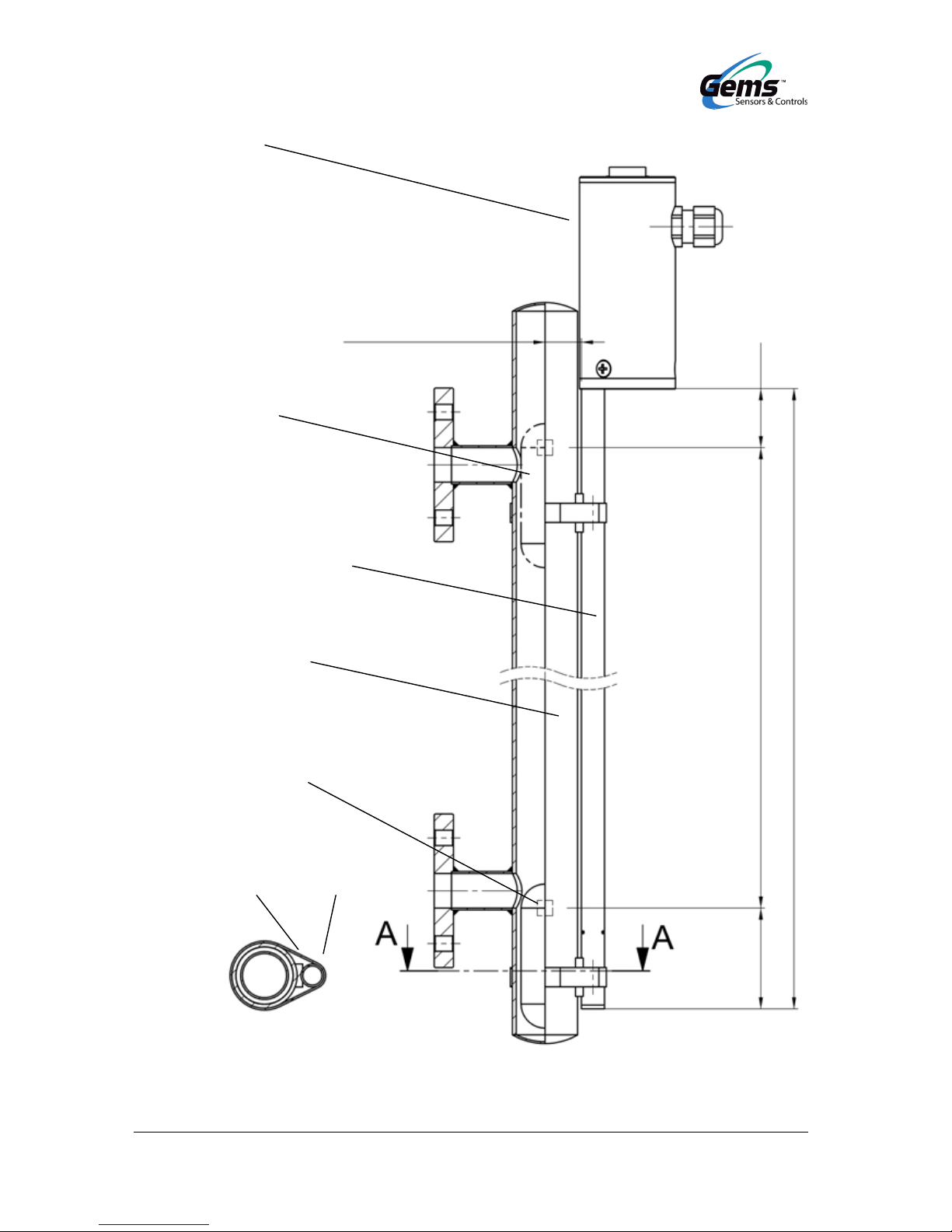
4.3 Installation on the bypass
The level sensor is installed on the bypass tube using suitable fasteners (nonmagnetic).
To ensure reliable gauging, the probe tube must be fitted with no
deformation on the outside.
The distance between the probe and bypass tubes must be as small as
possible.
Only floats approved by GEMS Sensors & Contr0ls can be used.
Page 11
XT-1000 Page 11/19
Figure 5: installation with SureSite
Probe length
XT-1000-B
Distance between probe tube and float
center: max. distance from the SureSite
float
SureSite float
Probe tube
fitted without tension
(undeformed)
SureSite housing
Magnet position
SECTION A-A
Spacer
bracket
max. magnet position
min. magnet position
Measuring range
min. 2.76“
min. 1.97“
Probe fixture
(nonmagnetic)
Page 12
Page 12/19 XT-1000
5 Electrical connection
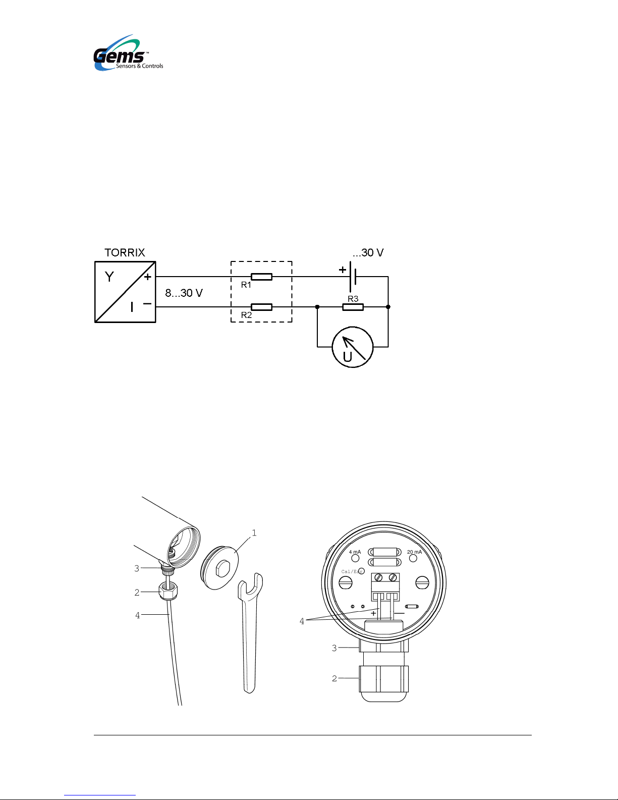
It is essential that the correct minimum wire gauge be selected: the supply voltage at the
level sensor must not fall below 8 V in the event of maximum current draw (21.5 mA).
The sensor head and probe tube of XT-1000 Standard are made of stainless steel.
The level sensor without Ex approval is installed in accordance with the following wiring
diagram:
Figure 6: wiring diagram for XT-1000
To connect the level sensor, see Figures 7:
Unscrew sensor head cap (1) using an open-ended spanner.
Loosen union nut (2) of screwed cable gland (3).
Figure 7: connecting the XT-1000 level sensor
Emax
Line resistors
Load
Voltage supply
DC
DC
Page 13
XT-1000 Page 13/19
Feed the two conductor cable (4) into the union nut and retighten the union nut.
The external diameter must be 0.2” to 0.4”.
Connect the two conductor cable to the screw terminals on the sensor head
marked (+) and (–). Observe the proper polarity.
Configuration of reference points if necessary (see section 6.1)
Screw the sensor head cap (1) back on.
The ground connector on the underside of the sensor head can be used for grounding or
equipotential bonding.
Protect the sensor head against the ingress of water. An external
cable diameter of 0.2” to 0.4” mm ensures reliable sealing of the
cable entry. Make sure that the cable gland is screwed tight, and
close the sensor head cap firmly.
Page 14
Page 14/19 XT-1000
6 User configuration
Versions that support the HART protocol enable the adjustments
described below to be carried out remotely without the sensor head having to be opened.
6.1 Measuring span at the level sensor
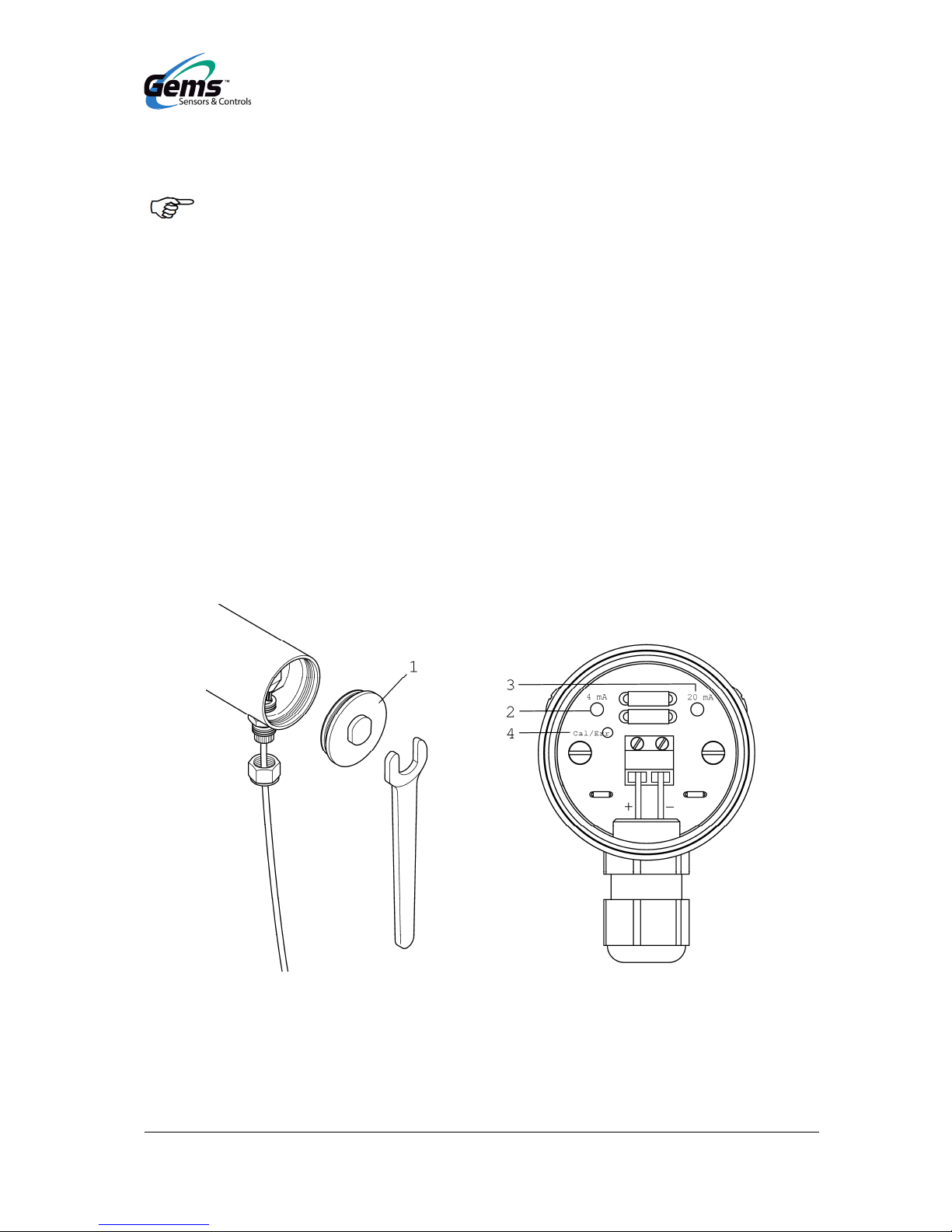
To enable configuration of the 4 mA and 20 mA points at the XT-1000 level sensor, two
buttons and an LED (light emitting diode) are provided near the terminals inside the
sensor head.
By default, the level sensor is set to maximum measuring span with 4 mA at the sensor
base and 20 mA at the sensor head. The measuring span is configurable for adaptation to
the tank concerned. However, a minimum clearance of 0.4” must be observed.
If this minimum clearance is not observed, the display direction of the level sensor will be
reversed automatically (ullage measurement).
Through configuration, it is also possible to have the measured value output inverted: e.g.
the level sensor can be set to maximum measuring span with 4 mA at the sensor head
and 20 mA at the sensor base.
Figure 8: configuring the measuring span
Unscrew sensor head cap (1) using an open-ended spanner.
Press and hold 4 mA button (2) or 20 mA button (3) for at least 3 seconds. The
green LED begins to flash.
Page 15
XT-1000 Page 15/19
The level sensor is now in configuration mode. The current consumption of the
level sensor is 12 mA. If no button is pressed again, the level sensor remains in
configuration mode for 20 seconds before reverting to measuring mode and discarding any changes. In configuration mode, the 4 mA or 20 mA reference point,
or both, can be modified in any order.
To define a reference point:
Move the float to the desired reference point
briefly press (0.1 to 2 seconds) “4 mA” button (2) to define a current consump-
tion of 4 mA at this position
briefly press (0.1 to 2 seconds) “20 mA” button (3) to define a current consump-
tion of 20 mA at this position
When the “4 mA” button is pressed, the LED goes out for 5 seconds. When the
“20 mA” button is pressed, the LED lights up permanently for 5 seconds.
The sensor then remains in configuration mode for a further 15 seconds before storing
the change and reverting to measuring mode.
The new measuring range configuration is not stored until the
level sensor reverts from adjustment mode to configuration mode
automatically and the LED goes out. The new configuration is retained even if the level sensor is subsequently disconnected from
the power supply.
For “dry” settings to be possible in the case of bypass sensors, a
magnetic system with spacer bracket will need to be obtained from the
manufacturer of the bypass. Configuration can then be carried out even
with the sensor removed.
Page 16
Page 16/19 XT-1000
6.2 Current consumption in failure mode
If a malfunction is preventing the level sensor from recording a plausible float position,
i.e. the measured level is incorrect, the sensor will enter failure mode after a short time.
Failure mode signalling conforms to the NAMUR NE43 recommendation. The failure
current is set by default to 21.5 mA but this value can also be set to 3.6 mA.
To configure current consumption in failure mode (see Figure 8)
Unscrew sensor head cap (1) using an open-ended spanner.
Press and hold both the “4 mA” (2) and “20 mA” (3) simultaneously for at least
3 seconds.
Green LED (4) “Cal/Err” flashes rapidly. The current consumption of the level sensor is 16
mA. After 5 seconds, the LED stops flashing and indicates the current consumption value
for failure mode for 2.5 seconds: if the LED lights up permanently, I
failure
= 21.5 mA; if the
LED goes out, I
failure
= 3.6 mA. If no button is pressed again, the level sensor remains in
failure mode for a further 2.5 seconds before reverting to measuring mode and
discarding the change.
To set a current consumption of 3.6 mA during the dwell period (10 s) in failure mode
briefly press “4 mA” button (2) (0.1 to 2 seconds).
To set a current consumption of 21.5 mA during the dwell period (10 s) in failure mode
briefly press “20 mA” button (3) (0.1 to 2 seconds).
The new measuring range configuration is not stored until the
level sensor reverts from adjustment mode to configuration mode
automatically and the LED goes out. The new configuration is retained even if the level sensor is subsequently disconnected from
the power supply.
Screw sensor head cap (1) back on.
If, during operation, the level sensor detects that the level cannot be
output correctly due to an insufficient supply voltage, it enters failure
mode and sets current consumption to 3.6 mA (regardless of any failure
current settings).
Page 17
XT-1000 Page 17/19
7 Technical data
7.1 Sensor
Electrical connection Two-line terminal
4 to 20 mA (3.8 to 20.5 mA) current consumption for level display
21.5 mA (3.6 mA) current consumption in failure mode
Supply voltage:
XT-1000
8 to 30 V DC
Process connection Screw-in unit with the option of infinitely variable
height adjustment
Standard G ½ (cutting ring coupling)
3” Ansi Flange
2” NPT screw-in unit
Sensor head Height 4.53”
Diameter 1.97”
Index of protection IP 68
Material: stainless steel
Cable diameter 0.2” to 0.4”
Temperature –40 °F to +185 °F
Probe tube Length 8” to 19’ (to order)
Diameter .47”
Material: 1.4571 standard
(titanium, Hastelloy C, or other materials on request)
Measuring range freely configurable (> 0.4”)
Normal temperature (NT) -40 °F to +250 °F
High temperature (HT) -40 °F to +450 °F
Ultra high temperature (HHT) -40 °F to +840 °F
Low temperature (LT) -85 °F to +250 °F
Communication HART protocol (optional)
Page 18
Page 18/19 XT-1000
Accuracy
Digital component
Linearity better than ± 0.04”or ±0.025 %,
better than ±0.001 % per K,
Repetition accuracy better than 0.004”
Resolution better than 0.002”
Accuracy
NT/LT Bypass digital
component
Linearity better than ±0.04” mm or ±0.025 %,
better than ±0.001 % per K,
Repetition accuracy better than 0.004”
Resolution better than 0.002”
Accuracy
Bypass HT/HHT digital
component
Linearity better than ±0.08” or ±0.1 %,
better than ±0.001 % per K,
Repetition accuracy better than 0.02”
Resolution better than 0.002”
Accuracy
Analog component
Linearity better than ±0.01 %
Temperature drift better than ±0.01 % per K
Resolution better than 0.5 μA (16 bit)
Page 19
XT-1000 Page 19/19
7.2 Floats
The float is a key component of the level sensor that must be matched to the medium in
respect of density, pressure resistance and material durability.
The following floats are exchangeable and are available to order separately. Other float
types and materials are available on request.
The density and magnet position of floats of the same type may vary
slightly, in which case readjustment may be required.
All floats are also suitable for use at a pressure of 1 bar (vacuum).
Excerpt from available float range:
min. density of
medium
[g/cm³]
Material max. operating pressure
[bar] at 68 °F *)
Shape
0.5
0.6
0.7
0.7
0.85
0.95
Titanium
1.4571 / 316 Ti
1.4571 / 316 Ti
C276
1.4571 / 316 Ti
1.4571 / 316 Ti
20
20
16
10
20
50
Ball ø 50
Ball ø 52
Cylinder ø 43
Cylinder ø 46
Ball ø 43
Ball ø 43
*) above 120 °F the maximum operating pressure decreases
Pressure resistance is guaranteed for undamaged floats only. Even
the most minor and invisible dents, which can occur if, for example, the float is dropped from a bench onto a stone floor, are sufficient to cause a significant deterioration in pressure resistance.
 Loading...