

Page 1

INSTALLATION
T o install the switches, use a suit able wrench on the port and plumb into place
with the proper sealant. For electrical wiring, refer to wiring codes on page 3
and to the specification sheet for the switch ratings. All switches are maintenance-free.
LOCATING AND ACCESSING THE ADJUSTER
PS31, PS32, PS51, PS52, PS61, PS62, PS83 and PS91:
The slotted adjustment screw is located on top of the unit. Using a flat bladed
screwdriver, turn the screw clockwise to increase the set point and counterclockwise to decrease the set point.
PS93:
The 5/64" Allen head screw is located inside the low-pressure port.
PS77:
Remove the front cover to reveal a hex adjuster nut, locking nut and the electrical
switch dead band thumbwheel.
PS11, PS41, PS71, PS72, PS75, PS76 and PS81:
Remove the plastic cover to reveal a 1/8” Allen head screw .
All Other Models with HC or HN Option:
Remove the screw in the center of the DIN adaptor. Remove the DIN adapter .
All Other Models without HC or HN Option:
Remove the 1/8” Allen head set screw at the top of the unit which serves as a
cover for the actual 1/8” Allen head adjustment screw .
Pressure Switches - Adjustable
Instruction Bulletin No. 208687
Rev B (CCPL)
Gems Sensors Ltd.
Lennox Road
Basingstoke
Hampshire RG22 4A W
United Kingdom
Tel: (44) 1256-320244
Fax: (44) 1256-810929
Gems Sensors Inc.
1 Cowles Road
Plainville,CT 06062-1198
U.S.A.
Tel: (1) 860-747-3000
Fax: (1) 860-747-4244
WARRANTY:
We guarantee this instrument against faulty workmanship and materials for a period of one year from date of delivery. The Company will
undertake to repair , free of charge, ex-works any instrument found to
be defective within the specified period; providing the instrument has
been used within the specifications, in accordance with these instructions, and has not been misused in any way.
Detailed notice of such defects and satisfactory proof thereof must
be given to the Company immediately after the discovery . The goods
are to be returned free of charge to the Company, packed and accompanied by a detailed failure report.
RETURN TO FACTORY:
T o comply with health and safety requirements, the instrument must
be clean and safe to handle and accompanied by a formal statement
to that effect; duly signed by an authorized officer of the Company.
Any instrument returned without certification will be quarantined and
no action will occur until cleared. It may ultimately be returned to
you, subject to a transportation charge.
1
4
www.gemssensors.com
Page 2

ADJUSTING THE SET POINT
All adjustments except for the PS93 are performed while applying a known
pressure (or vacuum) and monitoring the electrical contacts. The PS93 must be
removed from the system for adjustment and reinstalled to verify the setpoint.
PS31, PS32, PS51, PS52, PS61, PS62 and PS91:
Using a flat bladed screwdriver, turn the screw clockwise to increase the setpoint
and counterclockwise to decrease the setpoint.
PS83:
Using a flat bladed screwdriver, turn the screw clockwise to decrease the
vacuum setpoint and counterclockwise to increase the vacuum setpoint.
PS93:
Using a 5/64” Allen key , turn the screw clockwise to increase the dif ferential
setpoint and counterclockwise to decrease the differential setpoint.
PS77:
Pressure Adjustment: Using a 3/4” open-ended wrench, loosen the locknut.
Using a 5/8” open-ended wrench, turn the adjuster clockwise to increase the
setpoint and counterclockwise to decrease the setpoint. Once the desired
setting is obtained tighten the locknut with the 3/4” open-ended wrench while
holding the adjuster with the 5/8” open-ended wrench.
Deadband Adjustment: Turn the thumbwheel clockwise to increase the
deadband and counterclockwise to decrease the deadband. Deadband is the
difference in pressure between the increasing pressure setpoint and decreasing
pressure setpoint.
PS82:
Using a 1/8” Allen key , turn the screw clockwise to decrease the vacuum
setpoint and counterclockwise to increase the vacuum setpoint.
PS11 and All Other Models Using a 1/8” Allen key, turn the screw clockwise to
increase the setpoint and counterclockwise to decrease the setpoint.
VERIFICATION OF SETPOINT
Verify the new setpoint by slowly increasing and decreasing the pressure (or
vacuum) while monitoring the electrical contacts. Repeat the adjustment
procedure if necessary to obtain the desired setpoint.
REASSEMBLY (IF APPLICABLE)
PS77:
Install the front cover by tightening the four slotted screws.
PS41,PS71,PS72,PS75 and PS76:
Snap the plastic cover onto the electricalhousing.
All Other Models with HC or HN Option:
Install the DIN adapter. Install and tighten the screw .
All Other Models without HC or HN Option:
Install the 1/8” Allen adjustment screw cap at the top of the unit.
PRESSURE EQUIPMENT DIRECTIVE
The pressure switch is designed and
manfactured in accordance with Sound
Engineering Practice as defined by the
Pressure Equipment Directive 97/23/EC.
This pressure switch must not be used
as a “safety accessory” as defined by the
Pressure Equipment, Article 1, Paragraph
2.1.3.
The CE Mark on the unit does not relate
to the Pressure Equipment Directive.
2 3
How To Wire a DIN
Connector Code Circuit Wire Colors
Connector
Position
Black (Com) B
Red (NO) A
Black (Com) A
OR
Green (NC) B
Black (Com) C
Green (NC) B
Red (NO) A
Black (Com) 2
Red (NO) 1
Black (Com) 1
Green (NC) 2
Black (Com) C
Green (NC) B
Red (NO) A
Black (Com) 1
Green (NC) 2
Red (NO) 3
Wiring Chart
WM (uses Delphi
Male Terminal
P/N 12089040
WF (uses Delphi
Female Socket
P/N 12089188)
B
C
DE
Leads & Din
A
B
C
A
Page 3
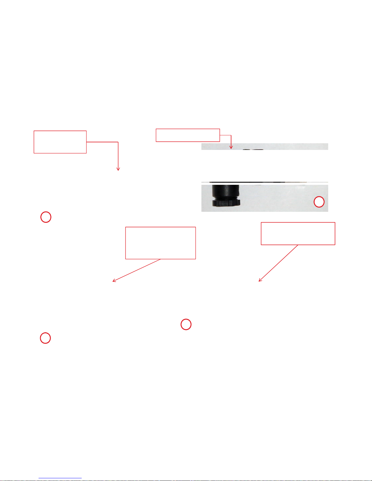
Undo Phillipshead screw
Remove DIN plug
Adjust switch point
with 1/8” Allen key
Remove brass
slotted-head screw
from DIN adaptor
1
2
3
4
 Loading...