

Page 1

FCC ID : PFMTC7730
GEMPACK CO., LTD.
Appendix F. Users Manual
Report No :E03.0718.FCC.404N
Issue of Date : July 18, 2003
TTeelleeCCLLIIEENNTT TTCC77773300 SSeerriieess
1. Preface...................................................................................................................................4
1.1. Purpose..........................................................................................................................4
1.2. Audience........................................................................................................................4
1.3. How To Use This Manual............................................................................................4
1.4. Statements....................................................................................................................5
1.4.1. European Telecom Statement ...........................................................................5
1.4.2. ENERGY STAR® .................................................................................................5
1.4.3. TeleVideo, Inc. Software License Agreement .................................................5
1.4.4. Grant.......................................................................................................................5
1.4.5. Limit of Liability.....................................................................................................6
1.4.6. U.S. Government Restricted Rights ..................................................................6
1.4.7. Declaration of Conformity...................................................................................6
1.4.8. Statement of Limited Warranty...........................................................................7
2. Introduction............................................................................................................................8
2.1. Safety Instructions........................................................................................................8
2.1.1. Safety Notices.......................................................................................................8
2.1.2. Other Product Safety Considerations ...............................................................9
2.2. Introduction..................................................................................................................10
2.2.1. Features...............................................................................................................11
2.3. Equipment Overview..................................................................................................11
3. Hardware Installation .........................................................................................................13
3.1. Rear Panel ...................................................................................................................13
3.1.1. I/O Por ts...............................................................................................................13
3.1.2. Connecting the TeleCLIENT TC7730.............................................................14
3.2. Powering on the TeleCLIENT TC7730...................................................................15
3.3. Front Control Panel ....................................................................................................15
3.3.1. Activity LED.........................................................................................................16
ETL Inc.
#584 Sangwhal -ri, Kanam-myon,
Yoju-kun, Kyounggi-do,
469-885, Korea 1 o 83f
17” Web Base Terminal
Model: TC7730
Page 2

FCC ID : PFMTC7730
GEMPACK CO., LTD.
Report No :E03.0718.FCC.404N
Issue of Date : July 18, 2003
Appendix F. Users Manual
3.3.2. Ethernet LED.......................................................................................................16
3.4. Troubleshooting..........................................................................................................16
3.5. PowerSaver.................................................................................................................17
4. Software Configuration......................................................................................................18
4.1. TeleCLIENT Setup Wizard .......................................................................................18
4.1.1. Network Settings................................................................................................19
4.1.2. Display Setting....................................................................................................31
4.1.3. Control Panel......................................................................................................33
4.2. Setting TeleCLIENT TC7730 Properties ................................................................48
4.2.1. General Tab........................................................................................................49
4.2.2. Local Resources Tab.........................................................................................50
4.2.3. Display Tab.........................................................................................................50
4.2.4. Experience Tab...................................................................................................51
4.2.5. Control Panel Tab ..............................................................................................52
4.2.6. Security Tab........................................................................................................52
4.2.7. Management Tab...............................................................................................54
4.2.8. Net-Info Tab ........................................................................................................56
5. Operation.............................................................................................................................58
5.1. Powering On ...............................................................................................................58
5.2. Using the TeleCLIENT Connection Manager ........................................................58
5.3. Configuring Network Connections...........................................................................59
5.3.1. Creating a New Connection ..............................................................................60
5.3.2. Editing Connections...........................................................................................71
5.3.3. Deleting a Connection.......................................................................................74
5.3.4. Setting Start-up Connections ...........................................................................75
5.4. Connecting to a Network Server..............................................................................76
5.5. Using the TeleCLIENT TC7730 Hot Keys..............................................................76
5.5.1. Starting Multiple Connections...........................................................................77
5.6. Logging Off..................................................................................................................78
6. Appendix A..........................................................................................................................79
5.6.1. Ending Auto-Start Connections........................................................................78
ETL Inc.
#584 Sangwhal -ri, Kanam-myon,
Yoju-kun, Kyounggi-do,
469-885, Korea 2 o 83f
17” Web Base Terminal
Model: TC7730
Page 3

FCC ID : PFMTC7730
GEMPACK CO., LTD.
Report No :E03.0718.FCC.404N
Issue of Date : July 18, 2003
Appendix F. Users Manual
6.1. Specifications..............................................................................................................79
6.1.1. TeleCLIENT TC7730 Hardware Specifications.............................................79
6.1.2. Networking, Communications And Input/Output Specifications .................80
6.1.3. TeleCLIENT TC7730 Software Specifications...............................................80
6.1.4. Environmental Specifications...........................................................................81
6.1.5. Regulatory Compliance Specifications ...........................................................82
6.1.6. Physical Specifications......................................................................................82
6.1.7. Warranty Information.........................................................................................82
ETL Inc.
#584 Sangwhal -ri, Kanam-myon,
Yoju-kun, Kyounggi-do,
469-885, Korea 3 o 83f
17” Web Base Terminal
Model: TC7730
Page 4

FCC ID : PFMTC7730
GEMPACK CO., LTD.
Report No :E03.0718.FCC.404N
Issue of Date : July 18, 2003
Appendix F. Users Manual
1. Preface
1.1. Purpose
The purpose of this manual is to provide installation and operation information for the
TeleCLIENT™ Windows® -Based Terminal.
1.2. Audience
This manual is intended for both authorized system administrators and users who have
experience with networking products and Windows-based terminals. It is assumed that
the personnel using this document have the appropriate background and knowledge to
use the TeleCLIENT.
1.3. How To Use This Manual
This manual is designed to help you locate information quickly and easily. Each chapter
contains the following information:
♦ Section 1: Preface
Provides equipment compliance, warranty and license agreement information.
♦ Section 2: Introduction
Describes the TeleCLIENT and provides basic safety information.
♦ Section 3: Hardware Installation
Describes how to install the TeleCLIENT hardware.
♦ Section 4: Software Configuration
Describes how to configure the TeleCLIENT software.
♦ Section 5: Operation
Provides instructions for using the TeleCLIENT Terminal Connection Manager and hot
keys.
ETL Inc.
#584 Sangwhal -ri, Kanam-myon,
Yoju-kun, Kyounggi-do,
469-885, Korea 4 o 83f
17” Web Base Terminal
Model: TC7730
Page 5

FCC ID : PFMTC7730
GEMPACK CO., LTD.
Report No :E03.0718.FCC.404N
Issue of Date : July 18, 2003
Appendix F. Users Manual
♦ Section 6: Appendix
System specifications and warranty information.
WARNING: THE PROCEDURES DESCRIBED IN THIS DOCUMEN T ARE INTENDED
FOR AUTHORIZED USERS ONLY. UNAUTHORIZED PERSONNEL PERFORMING
THESE PROCEDURES CAN AFFECT THE PRODUCT'S WARRANTY STATUS.
1.4. Statements
1.4.1. European Telecom Statement
The TeleCLIENT is intended for connection to a Network Centric System. DO NOT
connect the TeleCLIENT to the Telecom System.
1.4.2. ENERGY STAR®
As an ENERGY STAR Partner, TeleVideo, Inc. has determined that this product meets
the ENERGY STAR guidelines for energy efficiency. ENERGY STAR is a U.S.
registered mark.
1.4.3. TeleVideo, Inc. Software License Agreement
PLEASE CAREFULLY READ THE FOLLOWING TERMS AND CONDITIONS BEFORE
USING THIS SOFTWARE. USING THIS SOFTWARE INDICATES YOUR
ACCEPTANCE OF THE FOLLOWING TERMS AND CONDITIONS.
1.4.4. Grant
You may use the TeleCLIENT Connection Manager in conjunction with the TeleCLIENT
as provided. You may transfer ownership of the Equipment, including the right to
transfer the Software to another party so long as that party agrees to accept these
terms and conditions.
YOU MAY NOT COPY, MODIFY, TRANSLATE OR TRANSFER THE SOFTWARE, OR
MODIFICATION THEREOF, IN WHOLE OR IN PART, EXCEPT AS EXPRESSLY
PROVIDED FOR IN THIS LICENSE. YOU MAY NOT DECOMPILE, REVERSE
ENGINEER, OR OTHERWISE DECODE OR ALTER THE SOFTWARE PROVIDED
WITH THIS EQUIPMENT.
ETL Inc.
#584 Sangwhal -ri, Kanam-myon,
Yoju-kun, Kyounggi-do,
469-885, Korea 5 o 83f
17” Web Base Terminal
Model: TC7730
Page 6

FCC ID : PFMTC7730
GEMPACK CO., LTD.
Report No :E03.0718.FCC.404N
Issue of Date : July 18, 2003
Appendix F. Users Manual
1.4.5. Limit of Liability
UNDER NO CIRCUMSTANCES SHALL TELEVIDEO, INC. BE LIABLE FOR LOSS OF
DATA, COSTS, OR ANY INCIDENTAL OR CONSEQUENTIAL DAMAGES, HOWEVER
CAUSED AND ON ANY THEORY OF LIABILITY. THESE LIMITATIONS SHALL
APPLY EVEN IF TELEVIDEO, INC. OR ITS RESELLER HAS BEEN ADVISED OF THE
POSSIBILITY OF SUCH DAMAGES, AND NOTWITHSTANDING ANY FAILURE OF
ESSENTIAL PURPOSE OF ANY LIMITED REMEDY PROVIDED HEREIN.
WHEN USING T HIS PRODUCT, YOU AGREE THAT THESE ARE THE ONLY
APPLICABLE TERMS OF AGREEMENT BETWEEN US COVERING THE SOFTWARE.
1.4.6. U.S. Government Restricted Rights
This software is provided with RESTRICTED RIGHTS. Use, duplication or disclosure by
the Government is subject to restrictions as set forth in subparagraph (c)(1)(ii) of the
Rights in Technological Data and computer software clause at DFARS 252.227-7013 or
in subparagraphs (c)(1) and (2) of the Commercial Computer Software- Restricted
Rights at 8 C.F.R. 52 -227-19 as applicable. Contractor/Licensor is TeleVideo, Inc.
1.4.7. Declaration of Conformity
Manufacturer's Name: TeleVideo, Inc
Manufacturer's Address:
Type of Equipment:
2345 Harris Way
San Jose, CA 95131 USA
408.954.8333
www.televideo.com
Information Technology
Equipment (Computer Terminal)
ETL Inc.
#584 Sangwhal -ri, Kanam-myon,
Yoju-kun, Kyounggi-do,
469-885, Korea 6 o 83f
17” Web Base Terminal
Model: TC7730
Page 7

FCC ID : PFMTC7730
GEMPACK CO., LTD.
Report No :E03.0718.FCC.404N
Issue of Date : July 18, 2003
Appendix F. Users Manual
1.4.8. Statement of Limited Warranty
♦ Scope of Limited Warranty
TeleVideo, Inc. (TeleVideo) warrants to Buyer that its products, except software, will be
free from defects in materials and workmanship for 365 days from the date of purchase.
TeleVideo's obligation under this warranty will be limited to repairing or replacing, at
TeleVideo's option, the parts of the products which prove defective in material or
workmanship, provided that Buyer gives TeleVideo prompt notice of any defect and
satisfactory proof thereof.
♦ Exclusions
This limited warranty does not cover losses or damages which occur in shipment to or
from Buyer, nor due to (1) improper installation or maintenance, misuse, neglect or any
cause other than ordinary commercial or industrial application, or (2) adjustment, repair,
or modification by anyone other than TeleVideo's authorized agent, or (3) improper
environment, excessive or inadequate heating or air -conditioning and electrical power
failures, surges, or oth er irregularities, or (4) any statements made about TeleVideo's
products by sales representatives, dealers, distributors or agents, unless confirmed in
writing by a TeleVideo officer. Equipment purchased must be in a new, sealed
condition upon delivery to the end user in order to qualify for TeleVideo’s limited
warranty.
The foregoing TeleVideo limited warranty is in lieu of all other warranties, whether oral,
written, expressed, implied, or statutory. Implied warranties of merchantability and
fitness for a particular purpose will not apply.
TeleVideo’s warranty obligations and Buyer's remedies hereunder are solely and
exclusively as stated herein. TeleVideo makes no warranty whatsoever concerning any
software products, which are sold "as is" and "with all faults". TeleVideo's liability,
whether based on contract, tort, warranty, strict liability, or any other theory, shall not
exceed the price of the individual unit whose defect or damage is the basis of the claim.
In no event shall TeleVideo be liable for any loss of profits, loss or use of facilities or
equipment, or other indirect, incidental or consequential damages.
ETL Inc.
#584 Sangwhal -ri, Kanam-myon,
Yoju-kun, Kyounggi-do,
469-885, Korea 7 o 83f
17” Web Base Terminal
Model: TC7730
Page 8

FCC ID : PFMTC7730
GEMPACK CO., LTD.
Report No :E03.0718.FCC.404N
Issue of Date : July 18, 2003
Appendix F. Users Manual
2. Introduction
This chapter provides an overview of the TeleCLIENT Windows-Based Terminal. It
includes the following sections:
• Safety Instructions
• Introduction
• Equipment Overview
2.1. Safety Instructions
Please read this important safety information BEFORE using your TeleCLIENT and
save for later use.
2.1.1. Safety Notices
♦ Danger Notices
A danger notice indicates a hazard that could possibly cause deat h or serious personal
injury. Please note the following danger notices before using this product.
DANGER: THIS PRODUCT USES ELECTRICAL POWER AND CONTAINS
SENSITIVE COMPONENTS . IT IS NOT DESIGNED FOR CONSUMER SERVICING.
IF YOUR TELECLIENT REQUIRES REPAIR, OR YOU WISH TO ADD
COMPONENTS THAT REQUIRE OPENING THE CASE, PLEASE CONTACT YOUR
NEAREST SERVICE PROVIDER FOR ASSISTANCE. DO NOT ATTEMPT TO
SERVICE THE TELECLIENT YOURSELF. REFER ALL SERVICING TO QUALIFIED
SERVICE PERSONNEL. UNAUTHORIZED INDIVIDUALS WHO ATTEMPT TO
REPAIR THIS PRODUCT, OR TO INSTALL OR REPLACE COMPONENTS MAY
RISK ELECTRICAL SHOCK AND CAUSE THE PRODUCT WARRANTY TO BE VOID.
DANGER: TO AVOID A SHOCK HAZARD:
ETL Inc.
#584 Sangwhal -ri, Kanam-myon,
Yoju-kun, Kyounggi-do,
469-885, Korea 8 o 83f
17” Web Base Terminal
Model: TC7730
Page 9

FCC ID : PFMTC7730
GEMPACK CO., LTD.
Report No :E03.0718.FCC.404N
Issue of Date : July 18, 2003
Appendix F. Users Manual
• Connect the power cord to a properly wired and grounded power outlet.
• Make sure that any equipment attached to this product is also properly
connected to wired receptacles.
DANGER: THE TELECLIENT POWER SWITCH IS NOT THE MAIN DISCONNECT.
THE MAIN POWER DISCONNECT IS THE DETACHA BLE LINE CORD.
♦ Warning Notices
A warning notice indicates the possibility of damage to a program, device, system or
data.
2.1.2. Other Product Safety Considerations
Please note the following:
1. Do not expose the power supply, TeleCLIENT, line cord or monitor to moisture, dust
or corrosive gases.
2. Position the TeleCLIENT in a w ell-ventilated area; do not allow debris near the
ventilation holes.
3. Keep the TeleCLIENT away from heat sources, including direct sunshine and
heating appliances. The maximum operating temperature is 35ºC (95ºF).
4. Always unplug the TeleCLIENT before cleaning. Do not use liquid cleaners or
aerosol cleaners. Use only a damp cloth for cleaning.
5. Make sure the TeleCLIENT is placed on a stable surface.
6. Do not block slots and openings anywhere on the TeleCLIENT.
7. Use only the type of power indicated on the marking label to operate this product.
Consult your dealer or local power company if you are unsure of the type of power
available.
8. Use only the proper type of power supply cord set (provided in your accessory box)
for this unit. Use a detachable type: UL listed/CSA certified, type SVT/SJT, rated as
10A 125V minimum, VDE approved or its equivalent.
9. Do not allow anything to rest on the power cord.
ETL Inc.
#584 Sangwhal -ri, Kanam-myon,
Yoju-kun, Kyounggi-do,
469-885, Korea 9 o 83f
17” Web Base Terminal
Model: TC7730
Page 10

FCC ID : PFMTC7730
GEMPACK CO., LTD.
Report No :E03.0718.FCC.404N
Issue of Date : July 18, 2003
Appendix F. Users Manual
10. If an extension cord is used with the TeleCLIENT make sure that the total ampere
ratings of all products plugged into the cord does not exceed the extension cord
ampere rating.
11. Do not insert objects of any kind through the TeleCLIENT slots.
12. Unplug this product from the wall outlet immediately and contact qualified service
personnel under the following conditions:
• When the power cord or plug is damaged or frayed.
• If liquid has been spilled into the TeleCLIENT or it has been exposed to rain or
water.
• If the TeleCLIENT has been dropped or damaged.
13. Install the socket-outlet near the equipment and make sure it is easily accessibl e.
2.2. Introduction
Thank you for choosing the TeleCLIENT Windows-Based Terminal. The TeleCLIENT
is a “Powered by Microsoft Windows CE” Windows® -based terminal that empowers
users to access and manage business -critical applications such as:
• Point-of- sale
• Help and reservation desk
• Electronic Commerce
• Word-processing
• Spreadsheets
All can be accessed through host Windows, or Unix servers and all within the familiar
Windows environment.
The TeleCLIENT provides the freedom to choose any of the following:
• Microsoft’s Remote Desktop Protocol (RDP®) protocol to communicate directly to
a server loaded with Microsoft Windows NT Server® 4.0, Terminal Server Edition,
Windows 2000 Terminal Services, Windows XP Professional, or Windows 2003
Server.
ETL Inc.
#584 Sangwhal -ri, Kanam-myon,
Yoju-kun, Kyounggi-do,
469-885, Korea 10 o 83f
17” Web Base Terminal
Model: TC7730
Page 11

FCC ID : PFMTC7730
GEMPACK CO., LTD.
Report No :E03.0718.FCC.404N
Issue of Date : July 18, 2003
Appendix F. Users Manual
• Citrix’s Independent Compu ting Architecture (ICA®) protocol to communicate
directly to a server loaded with Citrix WinFrame®, Citrix MetaFrame™, or Citrix
MetaFrame XP™.
• Direct connection to a legacy server to run terminal emulation, such as TeleVideo
910 or 915 (Optional).
• Each TeleCLIENT can be configured for communication directly via TCP/IP
(Transmission Control Protocol/Internet Protocol) or PPP (Point-to-Point Protocol).
2.2.1. Features
The TeleCLIENT offers the following features:
• Ease of Installation and Administration
The Microsoft Windows CE Operating System is embedded on a 8MB local flash
disk. The software can be upgraded and re-programmed locally or remotely via
Ethernet download.
More Secure than PCs
•
Since there is no local storage system, administrators may keep all confidential
and business-critical files and data on the server to preserve data security and
integrity.
• Multiple Protocols Support
System administrators may choose the Remote Desktop Protocol (RDP) that
executes on Microsoft Windows NT Server 4.0, Terminal Server Edition, Windows
2000 Terminal Services, Windows .Net Server, or the Independent Computing
Architecture (ICA) protocol through Citrix MetaFrame, MetaFrame XP, or
WinFrame server systems to best fit their needs.
• Touch Screen Support
TeleCLIENT supports the 3M Touch Systems® and Elo TouchSystems® Screens
to provide POS and kiosks solutions.
• Innovative, Functional and Modular Design
The all-in-one LCD TeleCLIENT’s compact design is the ideal solution for limited
workspaces.
2.3. Equipment Overview
Your TeleCLIENT comes with everything needed to access your network server running
under Microsoft Windows NT Server 4.0, Terminal Server Edition, Windows 2000
ETL Inc.
#584 Sangwhal -ri, Kanam-myon,
Yoju-kun, Kyounggi-do,
469-885, Korea 11 o 83f
17” Web Base Terminal
Model: TC7730
Page 12

FCC ID : PFMTC7730
GEMPACK CO., LTD.
Report No :E03.0718.FCC.404N
Issue of Date : July 18, 2003
Appendix F. Users Manual
Terminal Services, Citrix WinFrame or MetaFrame or other legacy server operating
systems.
You will find the following items in your package:
• Integrated 17” TFT LCD TeleCLIENT Windows-Based Terminal
• Keyboard: Windows compatible
• Two-button mouse: Standard
• Inline power supply: Universal power supply standard
• Power Line cord
• CD- ROM version of TeleCLIENT User’s Manual
ETL Inc.
#584 Sangwhal -ri, Kanam-myon,
Yoju-kun, Kyounggi-do,
469-885, Korea 12 o 83f
17” Web Base Terminal
Model: TC7730
Page 13
FCC ID : PFMTC7730
GEMPACK CO., LTD.
Report No :E03.0718.FCC.404N
Issue of Date : July 18, 2003
Appendix F. Users Manual
3. Hardware Installation
This chapter explains how to install, connect and set -up the TeleCLIENT TC7730
hardware. It includes the following sections:
• Connecting to I/O Ports
• Powering on the TeleCLIENT TC7730
• Front Panel Controls
Troubleshooting
•
• PowerSaver
3.1. Rear Panel
3.1.1. I/O Ports
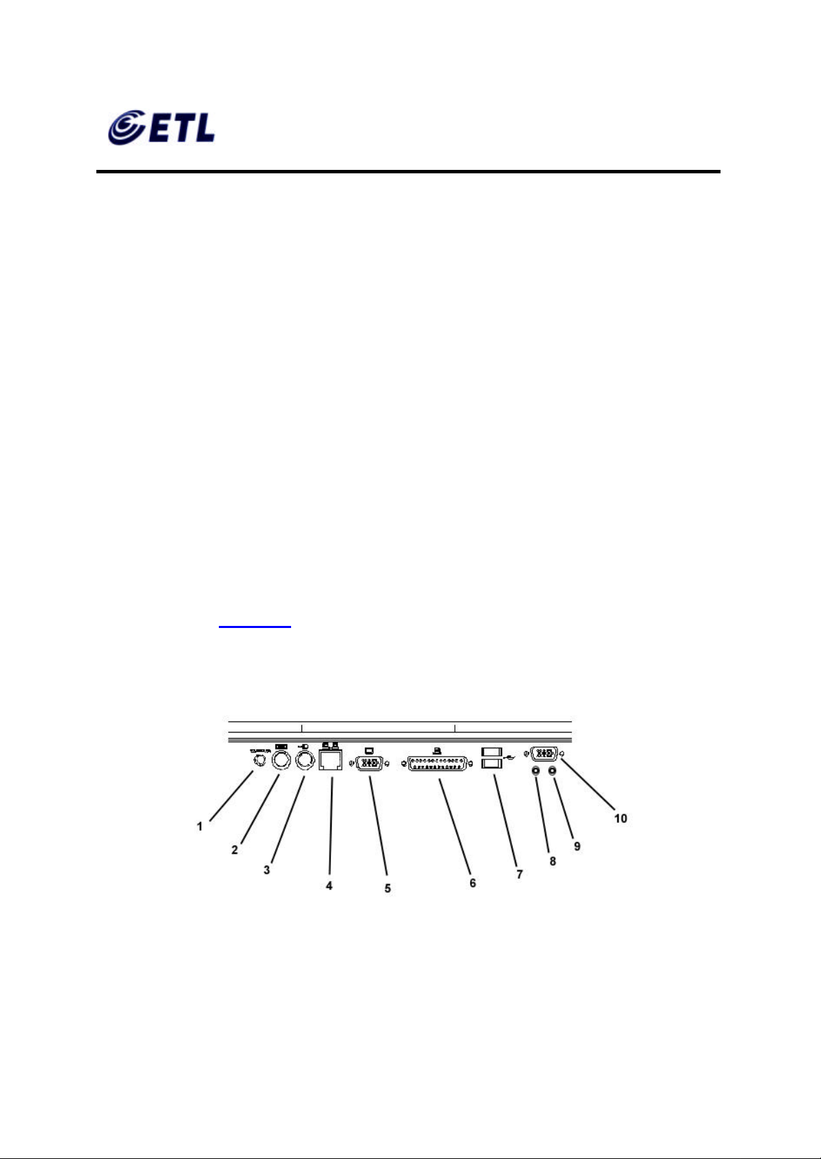
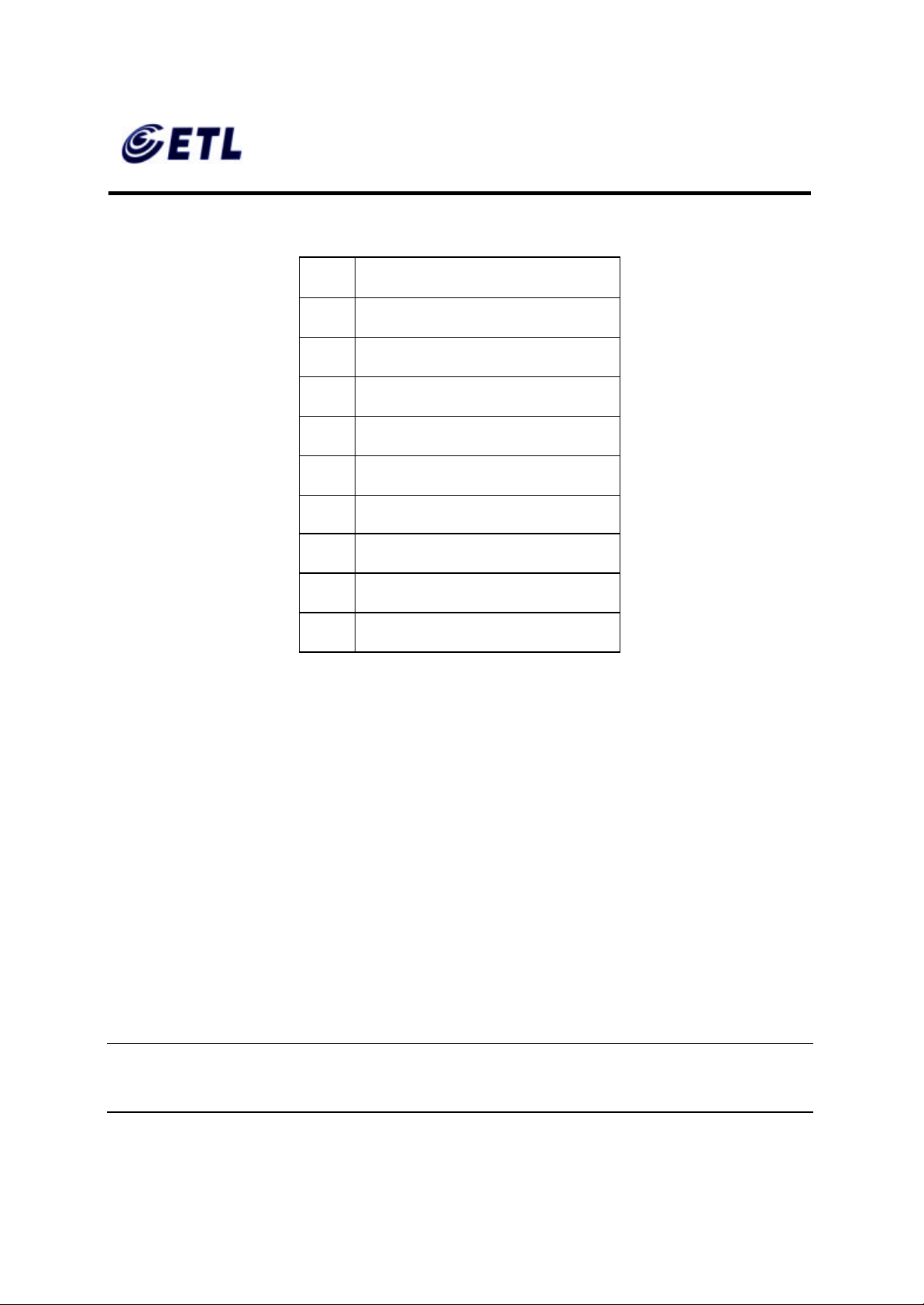
The I/O ports for the TC7730 are located at the bottom of the unit while putting the LCD
panel face down (Figure 3.1). These include:
I/O Ports
ETL Inc.
#584 Sangwhal -ri, Kanam-myon,
Yoju-kun, Kyounggi-do,
469-885, Korea 13 o 83f
17” Web Base Terminal
Model: TC7730
Page 14
FCC ID : PFMTC7730
GEMPACK CO., LTD.
Appendix F. Users Manual
1 DC-in
2 PS/2 Keyboard
3 PS/2 Mouse
4 Ethernet LAN
5 External VGA/SVGA
6 Printer/Parallel Port
7 USB Ports
8 Earphone
Report No :E03.0718.FCC.404N
Issue of Date : July 18, 2003
9 Microphone
10 Serial Port
3.1.2. Connecting the TeleCLIENT TC7730
1. Remove the TeleCLIENT TC7730, line cord, and accessories from the carton, and
set the unit on a flat work-surface.
2. Connect the keyboard to the keyboard connector.
3. Connect the mouse to the mouse connector.
4. Depending on configuration needs, connect a printer to the parallel port, USB port,
or other peripheral devices.
5. Depending on your hardware, connect to the host:
•
If using a network connection, connect a 10/100Base-T, twisted-pair, Category 5
RJ45 cable to the network port.
NOTE : THE TC7730 SUPPORTS BOTH 10 MBPS AND 100 MBPS LAN ACCESS.
TO ENSURE PROPER 100 MBPS OPERATION THE ETHERNET LAN CABLES
MUST BE OF CATEGORY 5 TYPE.
ETL Inc.
#584 Sangwhal -ri, Kanam-myon,
Yoju-kun, Kyounggi-do,
469-885, Korea 14 o 83f
17” Web Base Terminal
Model: TC7730
Page 15

FCC ID : PFMTC7730
GEMPACK CO., LTD.
Report No :E03.0718.FCC.404N
Issue of Date : July 18, 2003
Appendix F. Users Manual
6. Plug the AC cord into an AC outlet.
CAUTION: DO NOT FORCE THE CONNECTORS INTO THE SOCKETS. IF THERE
IS UNDUE RESISTANCE, MAKE SURE THE CONNECTOR IS PLACED CORRECTLY
IN THE SOCKET.
3.2. Powering on the TeleCLIENT TC7730
When connecting the TeleCLIENT TC7730 to AC outlets, please note the following:
1. To turn on your TC7730, simply press the power button on the front panel. This will
power on both the TeleCLIENT TC7730 terminal and the monitor. If the monitor
displays an image, installation is complete.
WARNING! TO PREVENT RISK OF FIRE OR ELECTRIC SHOCK, PLEASE FOLLOW
THESE INSTRUCTIONS CAREFULLY.
3.3. Front Control Panel
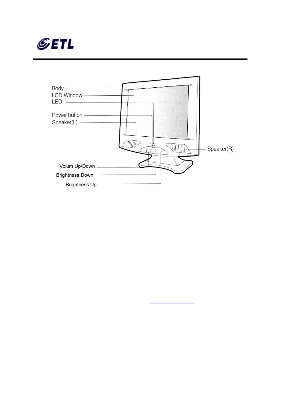
The front bezel of the TC7730 has three LED lights and other control buttons. The
power button is designed to turn on or off system under light pressure (Figure 3.2).
ETL Inc.
#584 Sangwhal -ri, Kanam-myon,
Yoju-kun, Kyounggi-do,
469-885, Korea 15 o 83f
17” Web Base Terminal
Model: TC7730
Page 16
FCC ID : PFMTC7730
GEMPACK CO., LTD.
Appendix F. Users Manual
Report No :E03.0718.FCC.404N
Issue of Date : July 18, 2003
Control Buttons
3.3.1. Activity LED
This LED blinks if there is any network activity.
3.3.2. Ethernet LED
This LED lights up only when the unit is connected at 100 Mbps.
3.4. Troubleshooting
Before calling for service, check the information in this section to see if the solution can
be found in this document or TeleVideo website ( www.televideo.com). If the problem
persists, please call the phone number on the warranty section.
♦ There is no screen image
• Check to see that the computer is plugged in and turned on.
ETL Inc.
#584 Sangwhal -ri, Kanam-myon,
Yoju-kun, Kyounggi-do,
469-885, Korea 16 o 83f
17” Web Base Terminal
Model: TC7730
Page 17

FCC ID : PFMTC7730
GEMPACK CO., LTD.
Report No :E03.0718.FCC.404N
Issue of Date : July 18, 2003
Appendix F. Users Manual
♦ The screen image is too light or too dark
• Adjust the brightness settings.
3.5. PowerSaver
This monitor has a built-in power management system called PowerSaver. This system
saves energy by switching your monitor into a low-power mode when it has not been
used for a certain amount of time. The monitor automatically returns to normal operation
when you move the computer's mouse or press a key on the keyboard. For energy
conservation, turn your monitor OFF when it is not needed, or when leaving it
unattended for long periods. Use the Software section of the manual to set up this
feature
ETL Inc.
#584 Sangwhal -ri, Kanam-myon,
Yoju-kun, Kyounggi-do,
469-885, Korea 17 o 83f
17” Web Base Terminal
Model: TC7730
Page 18
FCC ID : PFMTC7730
GEMPACK CO., LTD.
Report No :E03.0718.FCC.404N
Issue of Date : July 18, 2003
Appendix F. Users Manual
4. Software Configuration
The TeleCLIENT TC7730 software includes the TeleCLIENT Setup Wizard to assist
with the basic setup and software configuration. It includes the following sections:
• Using the TeleCLIENT Setup Wizard
• Resetting TeleCLIENT TC7730 properties to the factory default
• TeleCLIENT Software Update Procedure
4.1. TeleCLIENT Setup Wizard
NOTE: TELECLIENT WILL DETECT FOR DHCP SERVER ON THE NETWORK AT
POWER-ON. IF DHCP SERVICE IS NOT ACTIVATED THE CLIENT WILL ISSUE A
DEFAULT IP ADDRESS WHICH WILL HAVE TO BE CHANGED BY AN
ADMINISTRATOR.
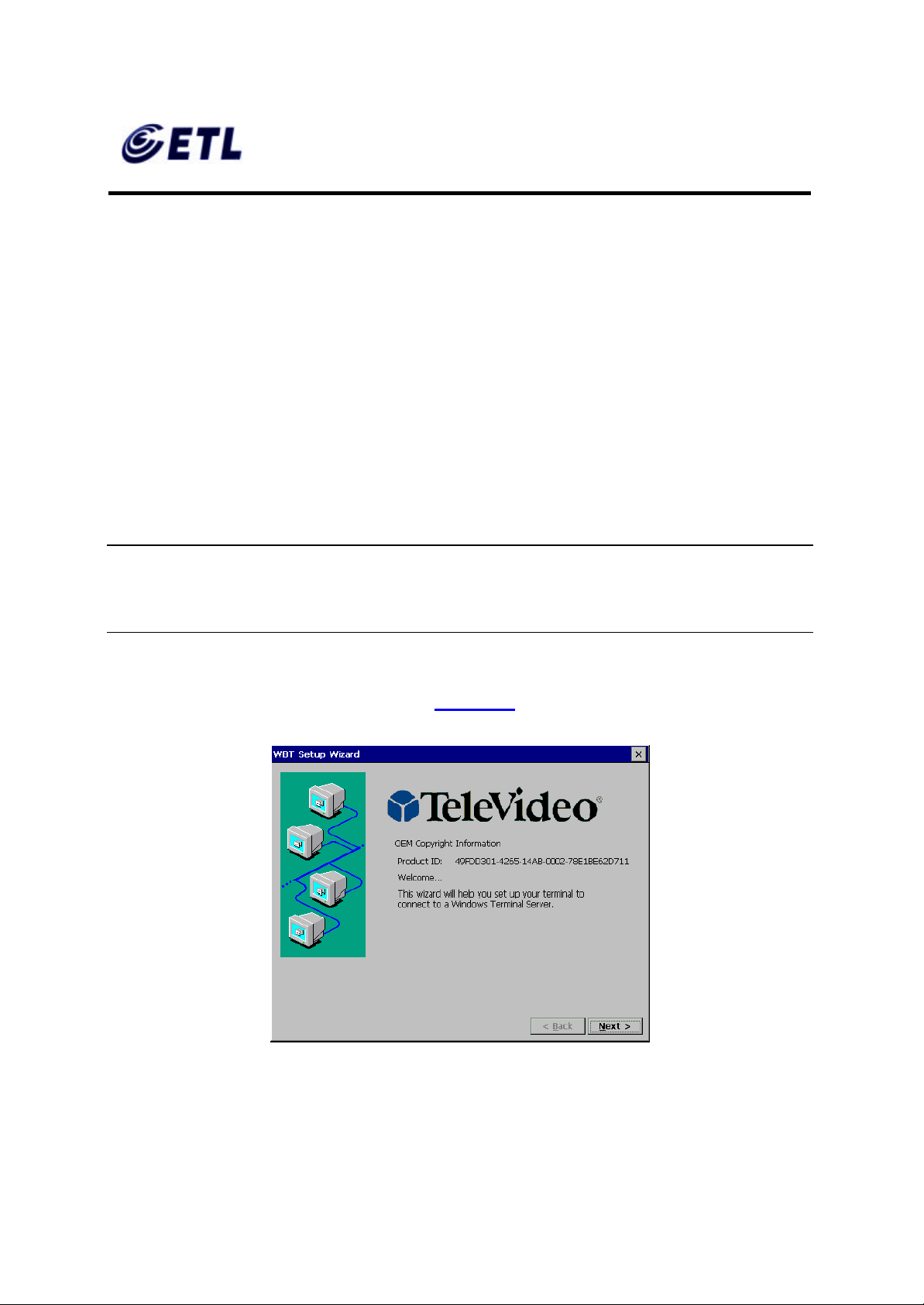
The first time power- up, the TeleCLIENT Setup Wizard welcome window will appear,
and guide through the TeleCLIENT setup (Figure 4.1).
Figure 4.1 TeleCLIENT Setup Wizard Welcome Window
ETL Inc.
#584 Sangwhal -ri, Kanam-myon,
Yoju-kun, Kyounggi-do,
469-885, Korea 18 o 83f
17” Web Base Terminal
Model: TC7730
Page 19
FCC ID : PFMTC7730
GEMPACK CO., LTD.
Appendix F. Users Manual
4.1.1. Network Settings
1. Click Next to start the setup procedure.
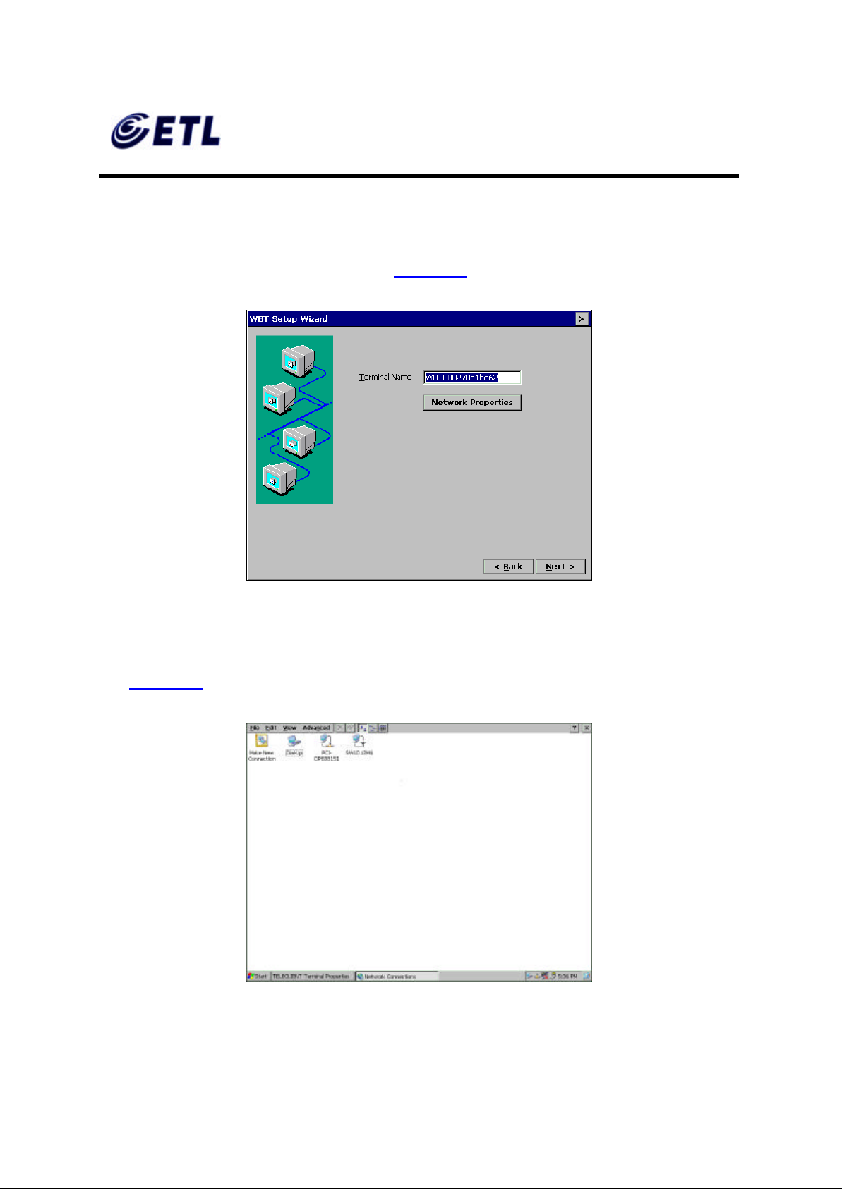
2. The Terminal Name window appears (Figure 4.2).
Report No :E03.0718.FCC.404N
Issue of Date : July 18, 2003
Figure 4.2 TeleCLIENT Setup Wizard Terminal Name Window
3. Type in the terminal name or leave the default name.
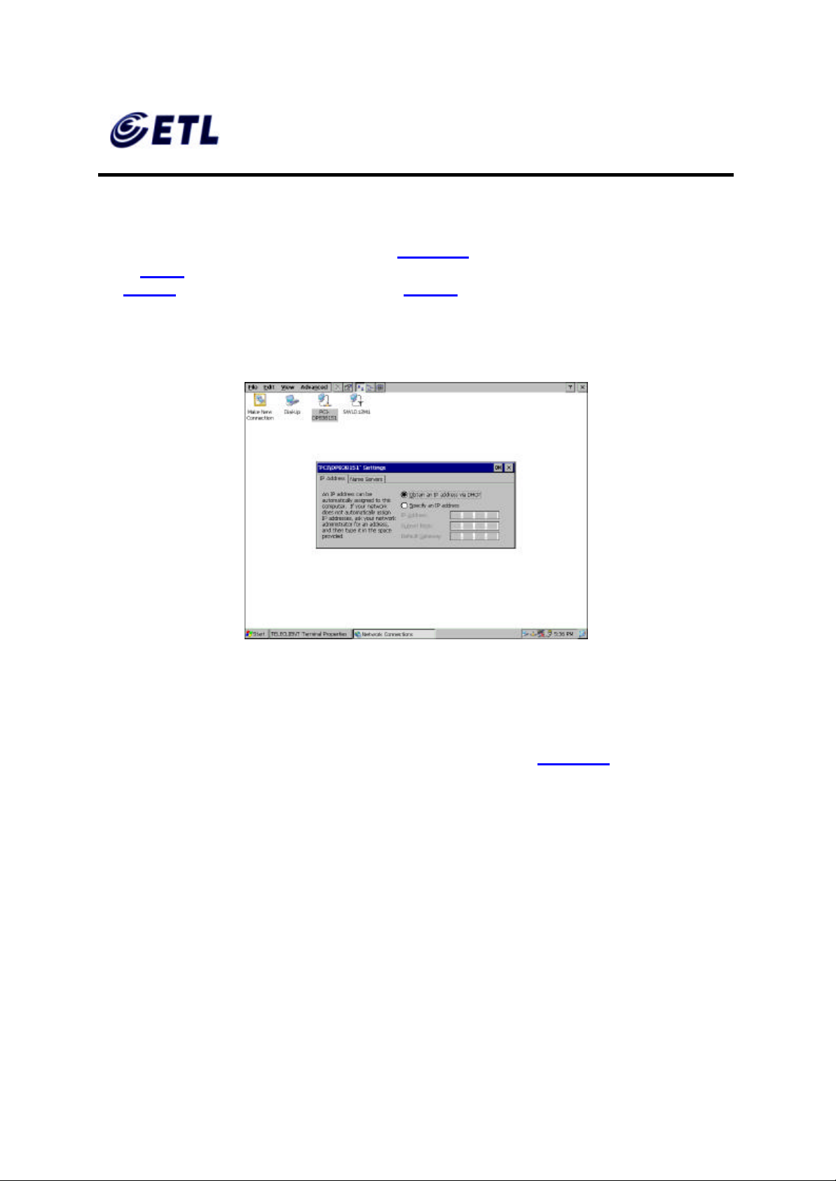
4. Click the Network Properties button and the network setup window will appear
(Figure 4.3).
Figure 4.3 Network Properties Window
ETL Inc.
#584 Sangwhal -ri, Kanam-myon,
Yoju-kun, Kyounggi-do,
469-885, Korea 19 o 83f
17” Web Base Terminal
Model: TC7730
Page 20
FCC ID : PFMTC7730
GEMPACK CO., LTD.
Report No :E03.0718.FCC.404N
Issue of Date : July 18, 2003
Appendix F. Users Manual
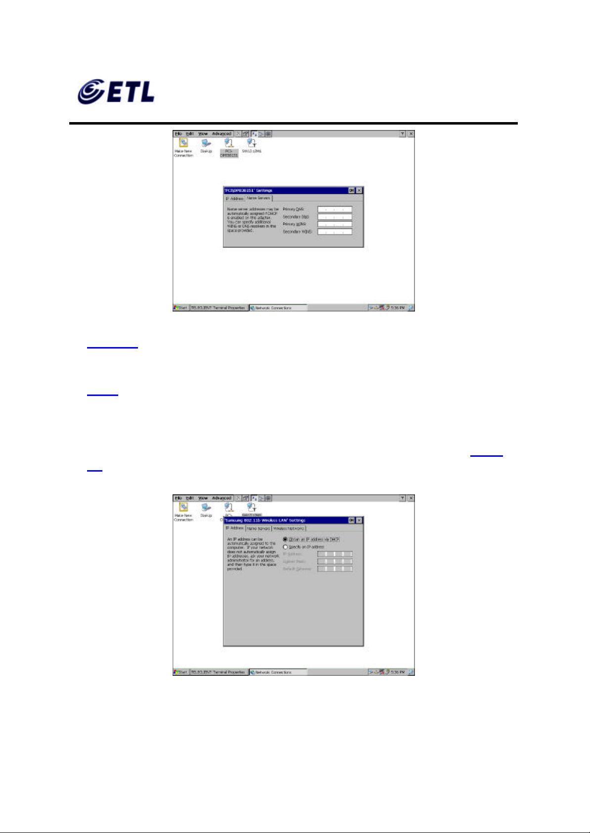
5. Depends on the TeleClient TC7730 series model, the screen will show different
network options. However, PCI -DP838151 Ethernet interface is the default choice
for all models. To configure PCI -DP838151, double click the PCI-DP838151 icon,
and TCP/IP setting screen will appear (Figure 4.4). If it is a wireless model then skip
to step 9. If dial-up connection using an external modem is required then skip to
step 26 . For direct connections, skip to step 42.
♦ Ethernet LAN Setup
Figure 4.4 PCI -DP838151 Network Interface Setting
6. If DHCP service is available choose the DHCP option and proceed to the next tab,
Name Servers. Otherwise, choose “Specify an IP address” and enter the static IP
address for the terminal, then click the Name Servers tab.
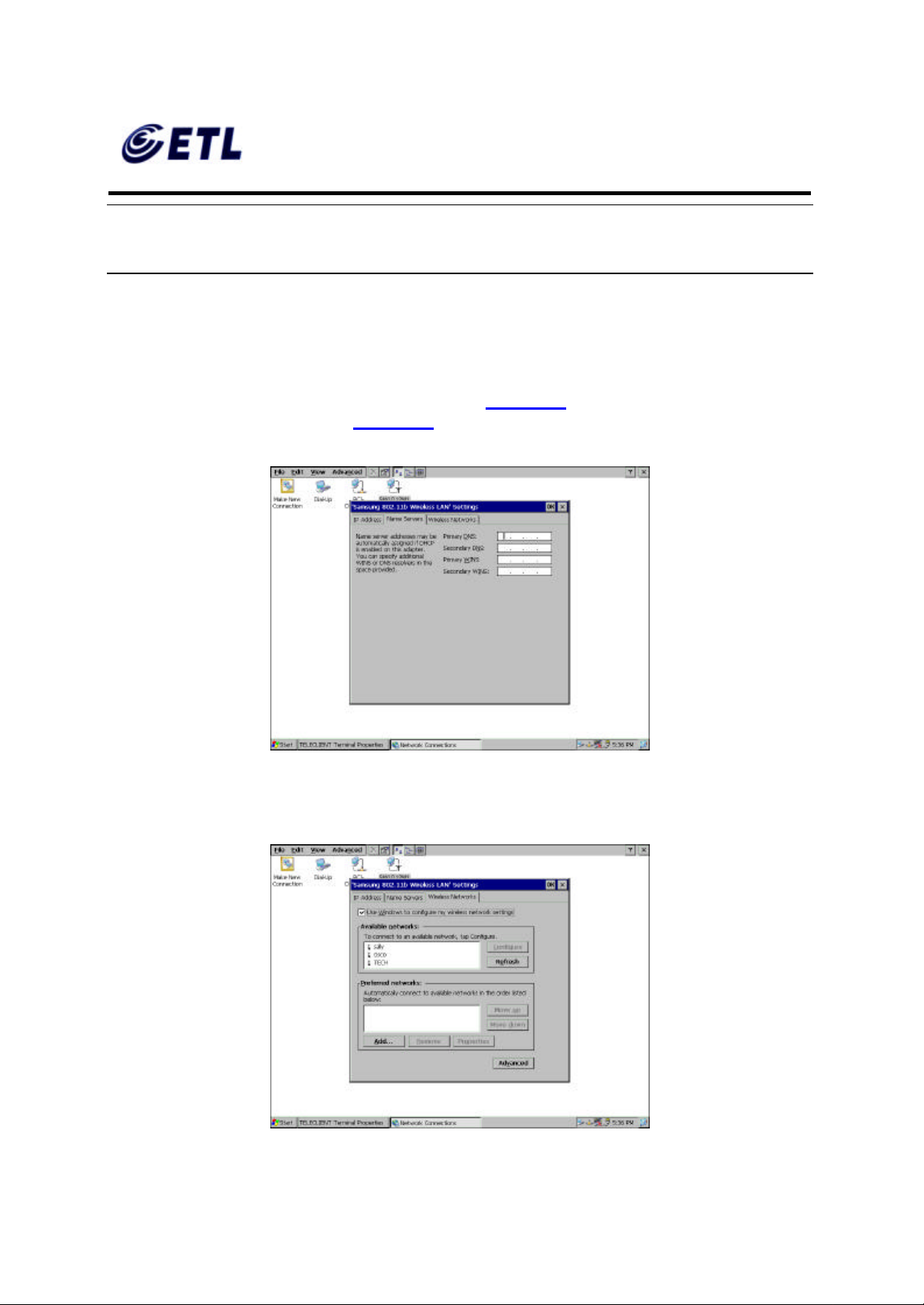
7. Enter the DNS server and WINS information then click OK (Figure 4.5)
ETL Inc.
#584 Sangwhal -ri, Kanam-myon,
Yoju-kun, Kyounggi-do,
469-885, Korea 20 o 83f
17” Web Base Terminal
Model: TC7730
Page 21
FCC ID : PFMTC7730
GEMPACK CO., LTD.
Report No :E03.0718.FCC.404N
Issue of Date : July 18, 2003
Appendix F. Users Manual
Figure 4.5 DNS/WINS Setting
8. Figure 4.3 should appear again. Close the window by clicking X then proceed to the
next step.
Default Connection Setup is complete here. If there are no other connections to create skip to
step 53.
♦ Wireless LAN Setup
9. Double click SWLD12M1 icon and wireless LAN setting window will appear (Figure
4.6).
Figure 4.6 SWLD12M1 Wireless LAN Setting
ETL Inc.
#584 Sangwhal -ri, Kanam-myon,
Yoju-kun, Kyounggi-do,
469-885, Korea 21 o 83f
17” Web Base Terminal
Model: TC7730
Page 22
FCC ID : PFMTC7730
GEMPACK CO., LTD.
Report No :E03.0718.FCC.404N
Issue of Date : July 18, 2003
Appendix F. Users Manual
NOTE: IN ORDER TO EN SURE THAT PCI-DP838151 DOES NOT OVERRIDE
SWLD12M1 WIRELESS CONNECTION, BE SURE TO DISABLE PCI -DP838151. TO
DO THAT, RIGHT-CLICK PCI-DP838151 ICON AND SELECT DISABLE.
10. If DHCP service is available choose the DHCP option and proceed to the next tab,
Name Servers. Otherwise, choose “Specify an IP address” and enter the static IP
address for the terminal, then click the Name Servers tab.
11. Enter the DNS server and WINS information (Figure 4.7) then proceed to the
‘Wireless Networks’ tab (Figure 4.8).
Figure 4.7 DNS/WINS Setting
ETL Inc.
#584 Sangwhal -ri, Kanam-myon,
Yoju-kun, Kyounggi-do,
469-885, Korea 22 o 83f
17” Web Base Terminal
Model: TC7730
Page 23
FCC ID : PFMTC7730
GEMPACK CO., LTD.
Report No :E03.0718.FCC.404N
Issue of Date : July 18, 2003
Appendix F. Users Manual
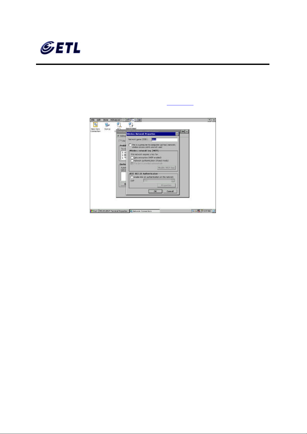
Figure 4.8 Wireless Networks Setting
12. Check the ‘Use Windows to configure my wireless setting (recommended), then click
Refresh to detect available access points.
13. Choose an access point then click Configure (Figure 4.9).
Figure 4.9 Access Point Setting
14. Assign a network name, SSID; the given network name should already be typed in.
15. Check if the wireless mode is used as Ad Hoc mode. The 802.11 standard supports
two network topologies: Ad Hoc and Infrastructure mode. A standalone Ad Hoc
network topology consists of at least two wireless stations without using access
points. This type of network is often referred to as Peer-to-Peer network because it
can be constructed quickly without much planning overhead. Ad Hoc mode LANs
are normally less expensive because they do not require a dedicated computer to
store applicat ions and data. However, they do not perform well for large networks.
16. Check the ‘ Data Encryption’ box if the network requires WEP service enabled.
Wired Equivalent Privacy is a security mechanism defined within the 802.11
standard designed to make the link integrity of the wireless medium equal to wired
cable. Data privacy mechanism based on a 40 bits (128 bit optional) shared key
algorithm, as described in the IEEE 802.11 standard.
17. Check the ‘ Network Authentication’ box if the network requires it to be in Shared
Mode. In Open System, the default authentication service that simply announces
the desire to associate with another station or access point. A station can
authenticate with any other station or access point using open system authentication
if the receiving station designates open system authentication. In Share Key , The
optional authentication that involves a more rigorous exchange of frames, ensuring
ETL Inc.
#584 Sangwhal -ri, Kanam-myon,
Yoju-kun, Kyounggi-do,
469-885, Korea 23 o 83f
17” Web Base Terminal
Model: TC7730
Page 24
FCC ID : PFMTC7730
GEMPACK CO., LTD.
Report No :E03.0718.FCC.404N
Issue of Date : July 18, 2003
Appendix F. Users Manual
that the requesting station is authentic. For a station to use shared key
authentication, it must implement WEP.
18. Check the ‘The key is provided automatically’ box if the network provides the key
automatically. Otherwise, leave the box unchecked and click Modify WEP Key to
supply all the necessary information on the screen, and then click OK.
19. Back on the Access Point Setting screen (Figure 4.9), check the box on the bottom
if the network uses IEEE 802.1x Authentication then choose the type. Click OK to
confirm.
20. Back on the Wireless Networks Setting screen (Figure 4.8), to select a preferred
network, highlight the desired access point from the ‘Available Networks’ box and
click Add. Configure the access point as steps from 14 thru 19. When this is done
the ‘Preferred Networks’ box should display the added access point.
21. If there are multiple access points displayed on the ‘Preferred Networks box’ then
highlight the chosen access point and use Move Up and Move Down buttons to
prioritize the list. Top of the list has the highest priority.
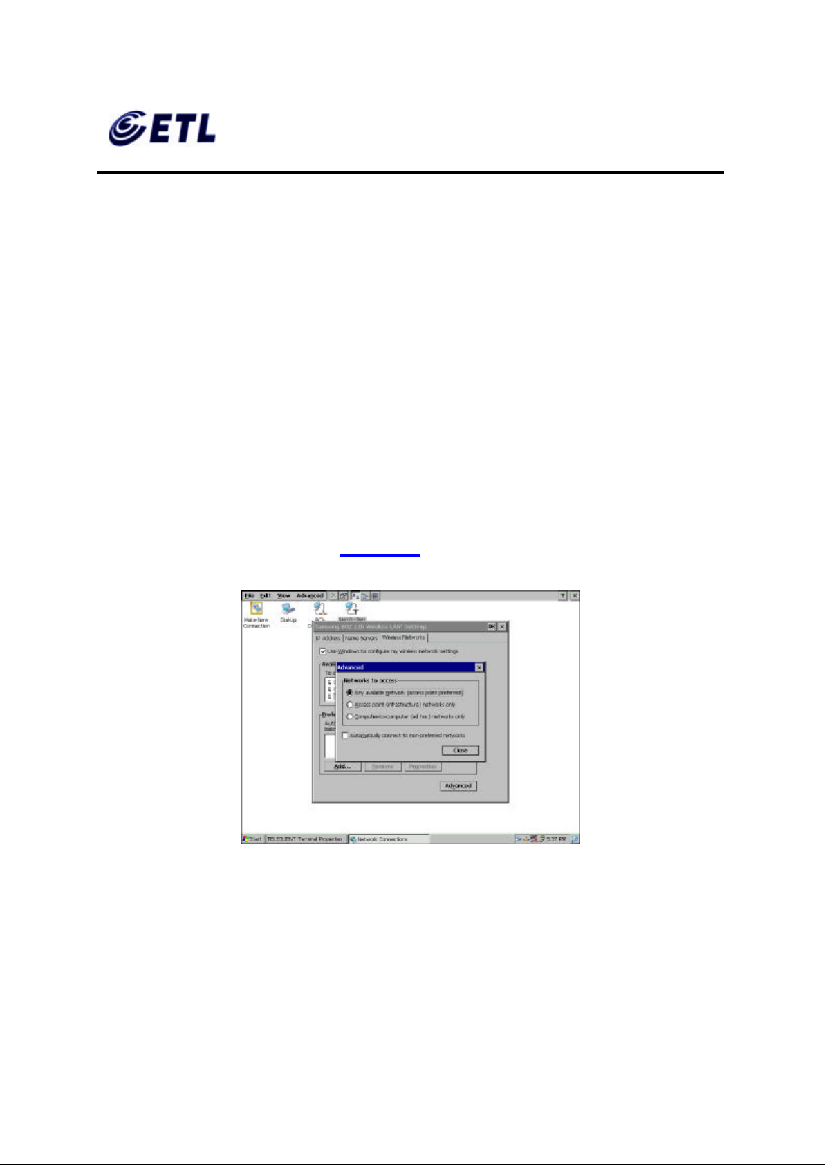
22. Click on the Advanced button (Figure 4.10).
Figure 4.10 Advanced Wireless Setting
23. Choose Networks to access.
24. Check the ‘Automatically connect to non-preferred networks’ box ONLY IF the
terminal is allowed to make connection to all the available access points.
25. Click Close to confirm, then click OK to finish wireless network settings.
ETL Inc.
#584 Sangwhal -ri, Kanam-myon,
Yoju-kun, Kyounggi-do,
469-885, Korea 24 o 83f
17” Web Base Terminal
Model: TC7730
Page 25
FCC ID : PFMTC7730
GEMPACK CO., LTD.
Report No :E03.0718.FCC.404N
Issue of Date : July 18, 2003
Appendix F. Users Manual
Wireless Connection Setup is complete here. If there are no other connections to create skip to
step 52.
♦ Dial-up Network Setup
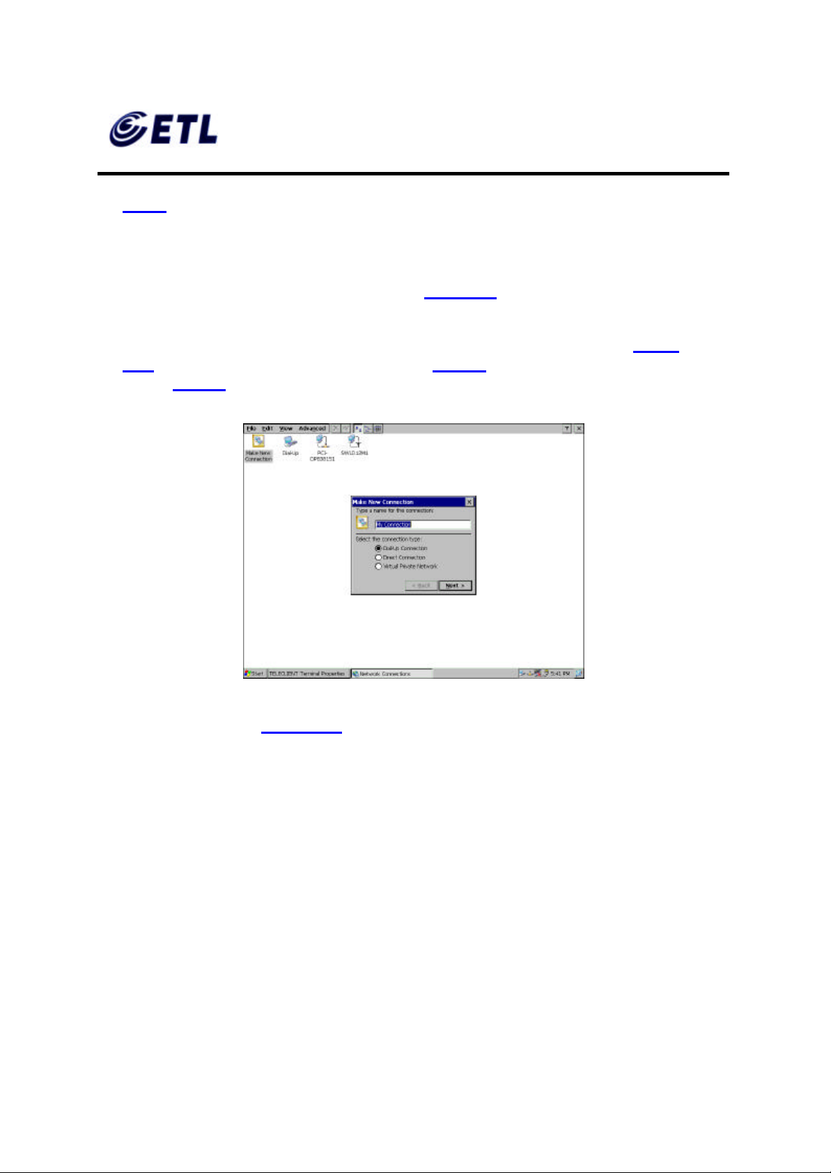
26. Back on the Network Properties screen (Figure 4.3); To create a dial-up connection,
double click on Make New Connection icon.
27. Type in the connection name, select a type of connection, and click Next (Figure
4.11): For a direct connection setup, skip to step 42. For a VPN connection, setup
skip to step 47.
Figure 4.11 Making New Connection
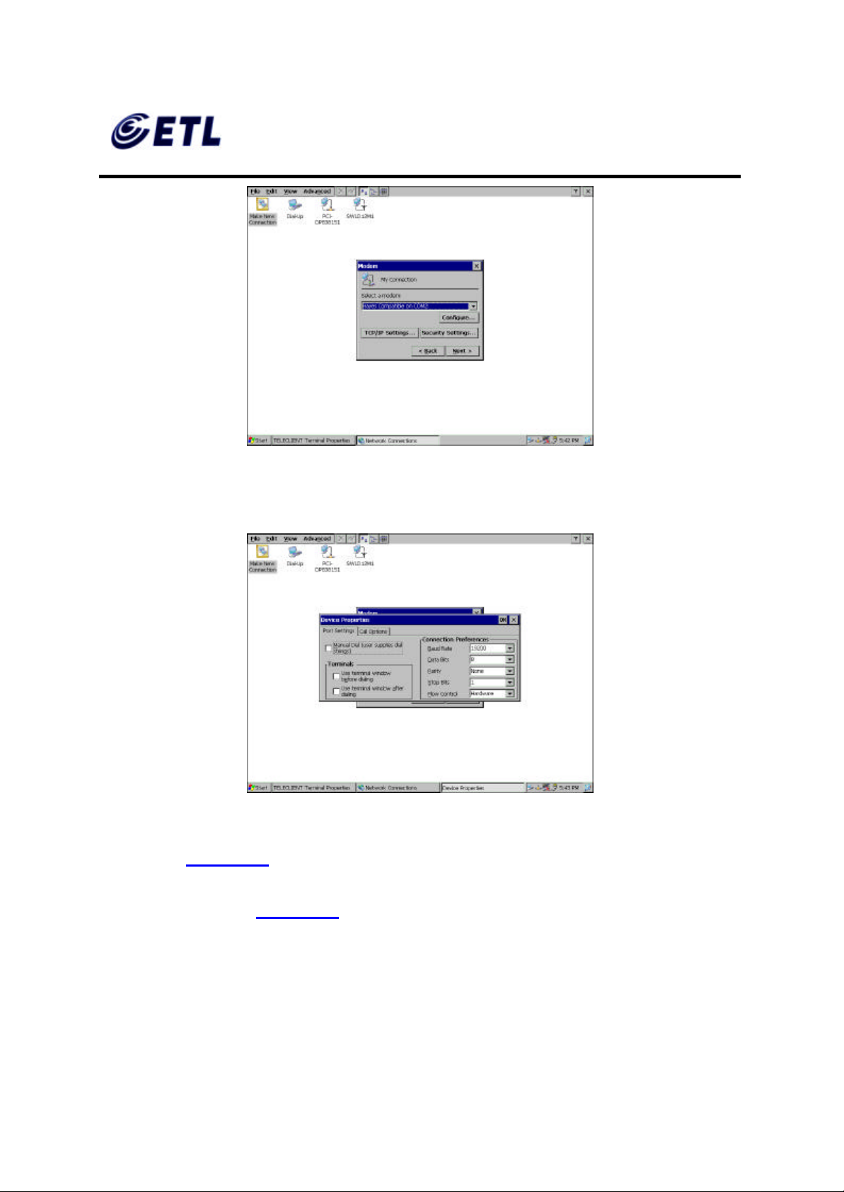
28. On the next screen (Figure 4.12 ), click on the drop-down box, and select the COM
port the modem is connected to.
ETL Inc.
#584 Sangwhal -ri, Kanam-myon,
Yoju-kun, Kyounggi-do,
469-885, Korea 25 o 83f
17” Web Base Terminal
Model: TC7730
Page 26
FCC ID : PFMTC7730
GEMPACK CO., LTD.
Appendix F. Users Manual
Figure 4.12 Making New Dial -up Connection
29. Click Configure.
Report No :E03.0718.FCC.404N
Issue of Date : July 18, 2003
30. Under the Port Settings tab, set Manual dialing option and the terminal screen
31. Set the modem connection by filling in the Connection Preferences boxes. Click on
Figure 4.13 Modem Settings
options (Figure 4.13).
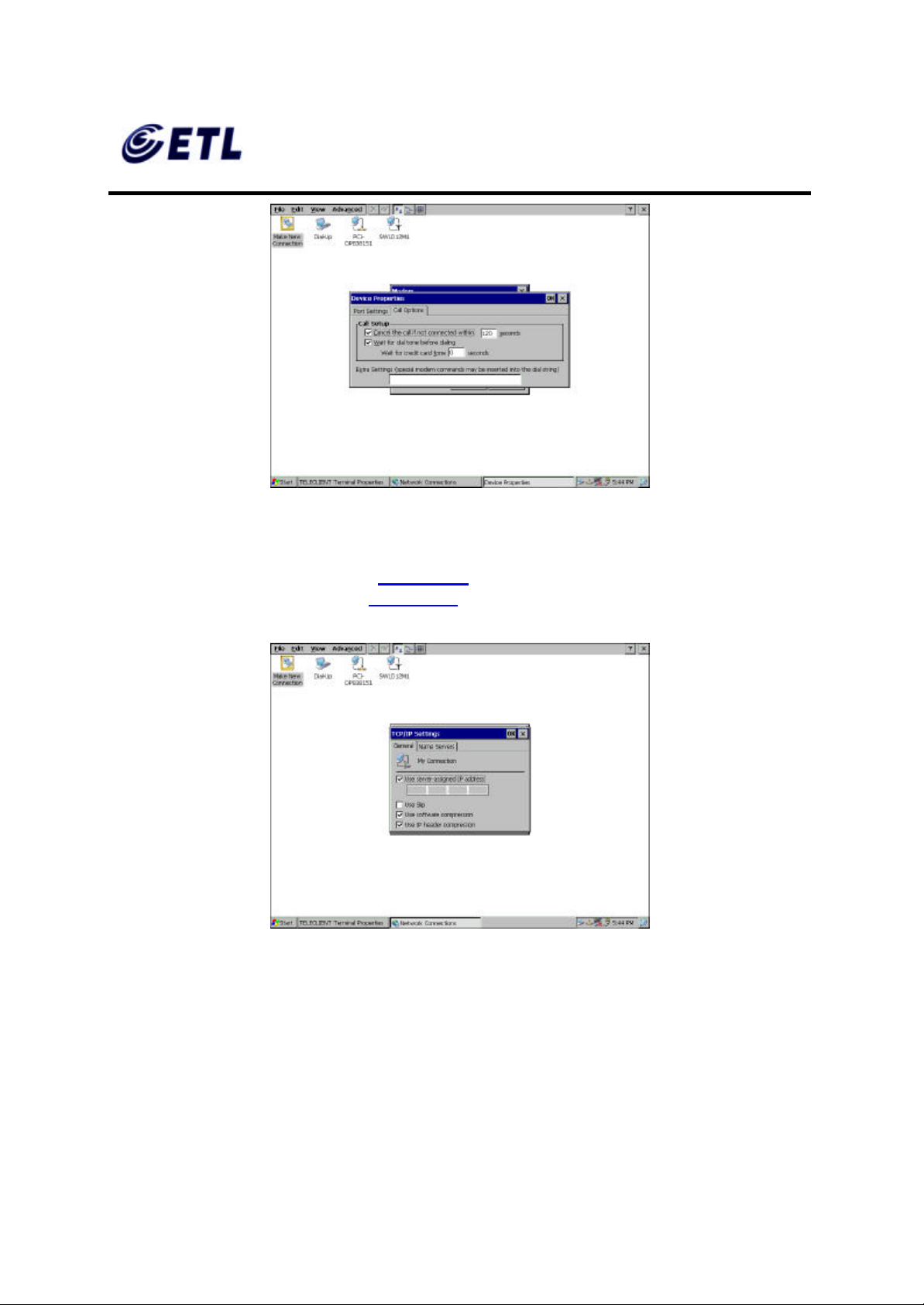
Call Options tab (Figure 4.14).
ETL Inc.
#584 Sangwhal -ri, Kanam-myon,
Yoju-kun, Kyounggi-do,
469-885, Korea 26 o 83f
17” Web Base Terminal
Model: TC7730
Page 27
FCC ID : PFMTC7730
GEMPACK CO., LTD.
Appendix F. Users Manual
Figure 4.14 Dialing Options
32. Set up calling options then click OK.
Report No :E03.0718.FCC.404N
Issue of Date : July 18, 2003
33. Back on New Dial -Up screen (Figure 4.12), click TCP/IP Settings button to
configure network properties (Figure 4.15 ).
Figure 4.15 Network Properties for Dial-up Connection
34. If a server issues the IP address then leave the box checked and proceed.
Otherwise, uncheck the box and assign the IP address.
35. Select SLIP if the network uses SLIP (Serial Line Internet Protocol) technology: An
Internet protocol used to run IP over serial lines such as telephone circuits or RS232 cables interconnecting two systems. SLIP is now being replaced by PPP, Pointto-Point Protocol, (Communication)
ETL Inc.
#584 Sangwhal -ri, Kanam-myon,
Yoju-kun, Kyounggi-do,
469-885, Korea 27 o 83f
17” Web Base Terminal
Model: TC7730
Page 28
FCC ID : PFMTC7730
GEMPACK CO., LTD.
Report No :E03.0718.FCC.404N
Issue of Date : July 18, 2003
Appendix F. Users Manual
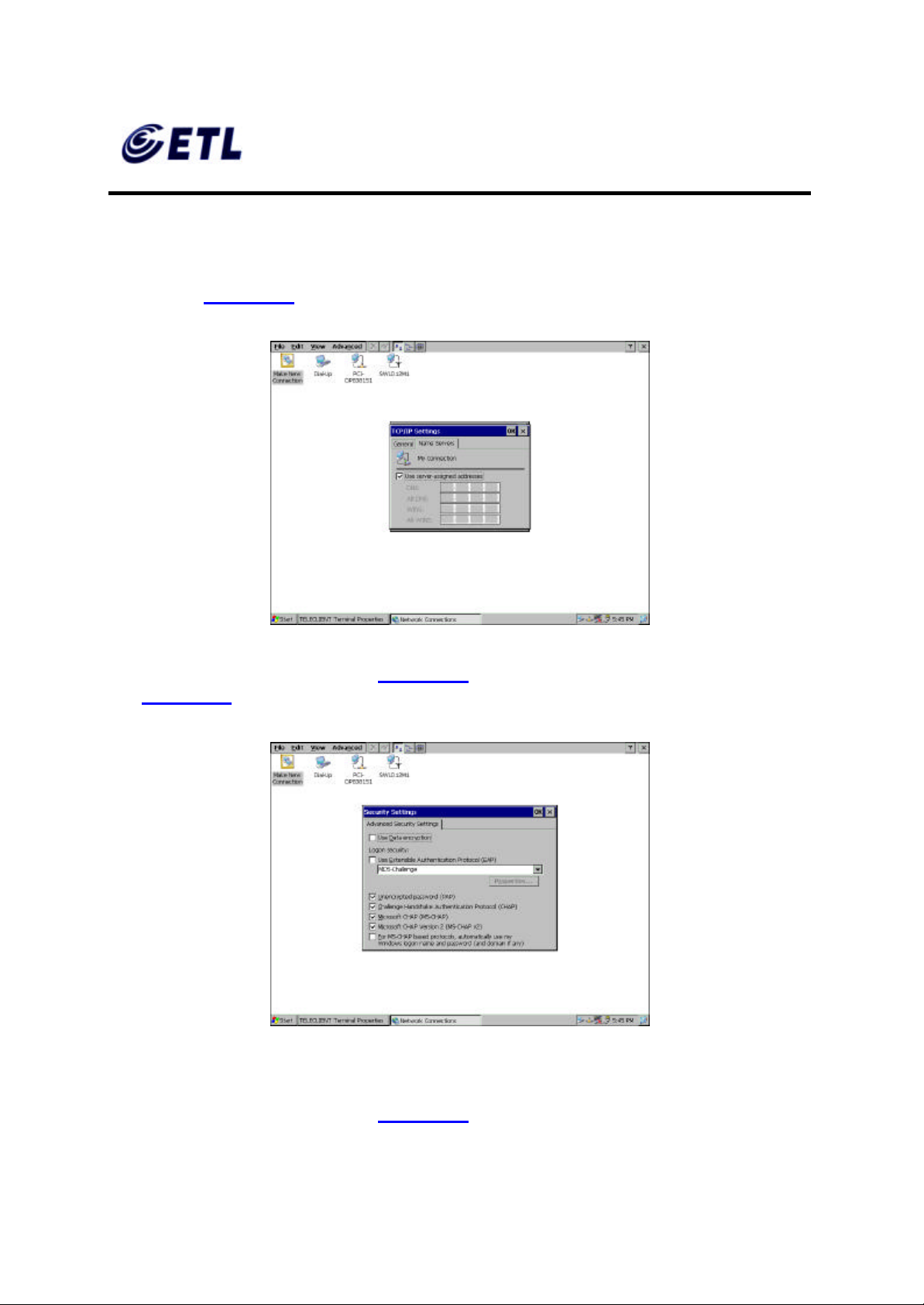
36. Check the compression options and click the Name Servers tab.
37. If a server issues the DNS information then leave the box checked and proceed.
Otherwise, uncheck the box and assign the DNS information, then click OK to
confirm (Figure 4.16).
Figure 4.16 DNS Settings
38. Back on New Dial -Up screen (Figure 4.12), click the Security Settings button
(Figure 4.17 ).
Figure 4.17 Dial-up Connection Security Settings
39. Setup the security options and click OK to confirm.
40. Back on New Dial -Up screen (Figure 4.12), click Next to proceed.
ETL Inc.
#584 Sangwhal -ri, Kanam-myon,
Yoju-kun, Kyounggi-do,
469-885, Korea 28 o 83f
17” Web Base Terminal
Model: TC7730
Page 29
FCC ID : PFMTC7730
GEMPACK CO., LTD.
Report No :E03.0718.FCC.404N
Issue of Date : July 18, 2003
Appendix F. Users Manual
Direct Connection Setup: skip to step 46.
VPN Connection Setup: skip to step 51.
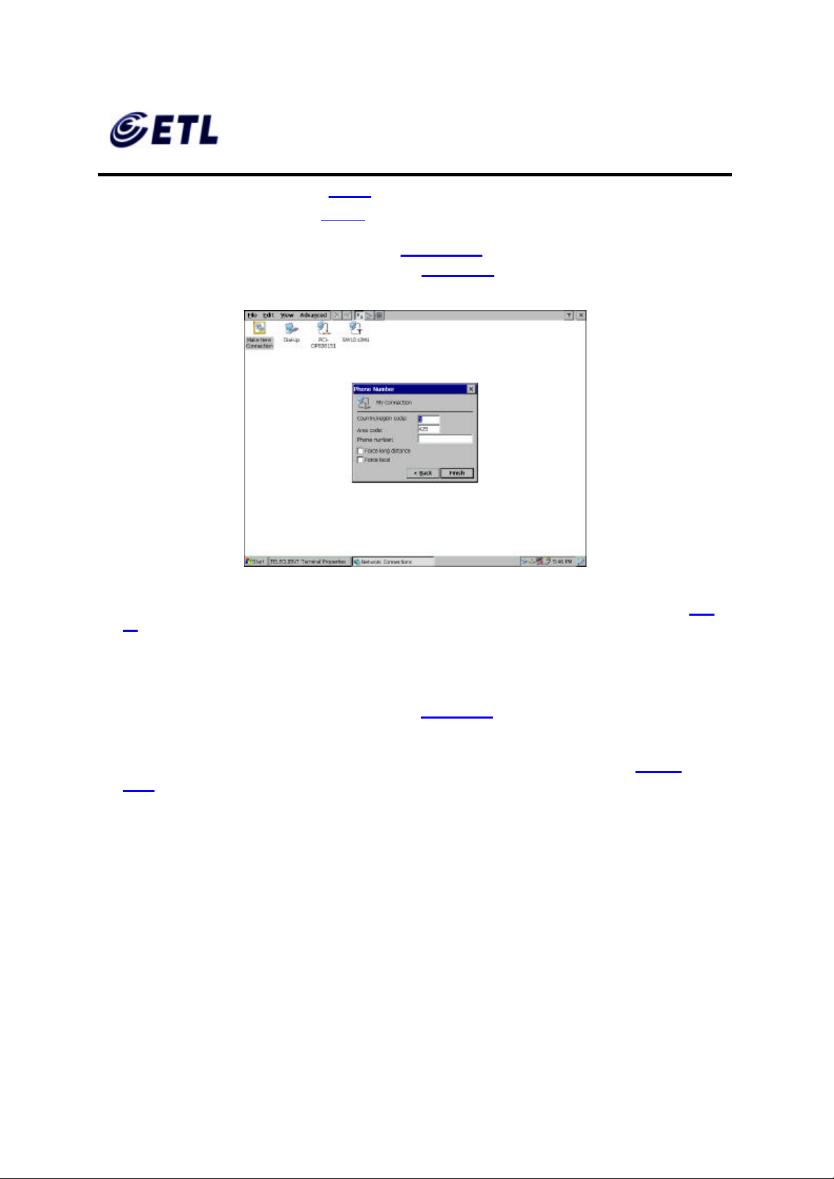
41. Set dialing prope rties and click Finish (Figure 4.18). A new connection icon should
appear on the Network Properties screen (Figure 4.3).
Figure 4.18 Dialing Properties
Dial-up Connection Setup is complete here. If there are no other connections to create skip to step
52.
♦ Direct Connection Setup
42. Back on the Network Properties screen (Figure 4.3), to create a Direct
Connection, double click on Make New Connection icon.
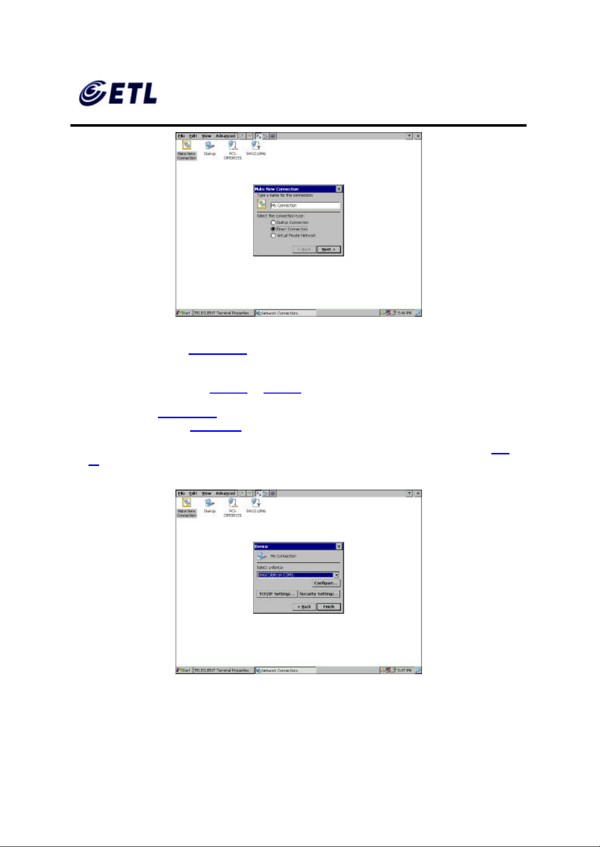
43. Type in the connection name, select Direct Connection, and click Next (Figure
4.19).
ETL Inc.
#584 Sangwhal -ri, Kanam-myon,
Yoju-kun, Kyounggi-do,
469-885, Korea 29 o 83f
17” Web Base Terminal
Model: TC7730
Page 30
FCC ID : PFMTC7730
GEMPACK CO., LTD.
Report No :E03.0718.FCC.404N
Issue of Date : July 18, 2003
Appendix F. Users Manual
Figure 4.19 Direct Connection Settings
44. On the next screen (Figure 4.20 ), click on the drop-down box, and select the COM
port the serial cable is connected to.
45. Follow instructions from step 28 to step 40.
46. Click Finish (Figure 4.20). A new connection icon should appear on the Network
Properties screen (Figure 4.3).
Direct Connection Setup is complete here. If there are no other connections to create skip to step
52.
Figure 4.20 Direct Connection Properties
ETL Inc.
#584 Sangwhal -ri, Kanam-myon,
Yoju-kun, Kyounggi-do,
469-885, Korea 30 o 83f
17” Web Base Terminal
Model: TC7730
Page 31
FCC ID : PFMTC7730
GEMPACK CO., LTD.
Report No :E03.0718.FCC.404N
Issue of Date : July 18, 2003
Appendix F. Users Manual
♦ VPN Connection Setup
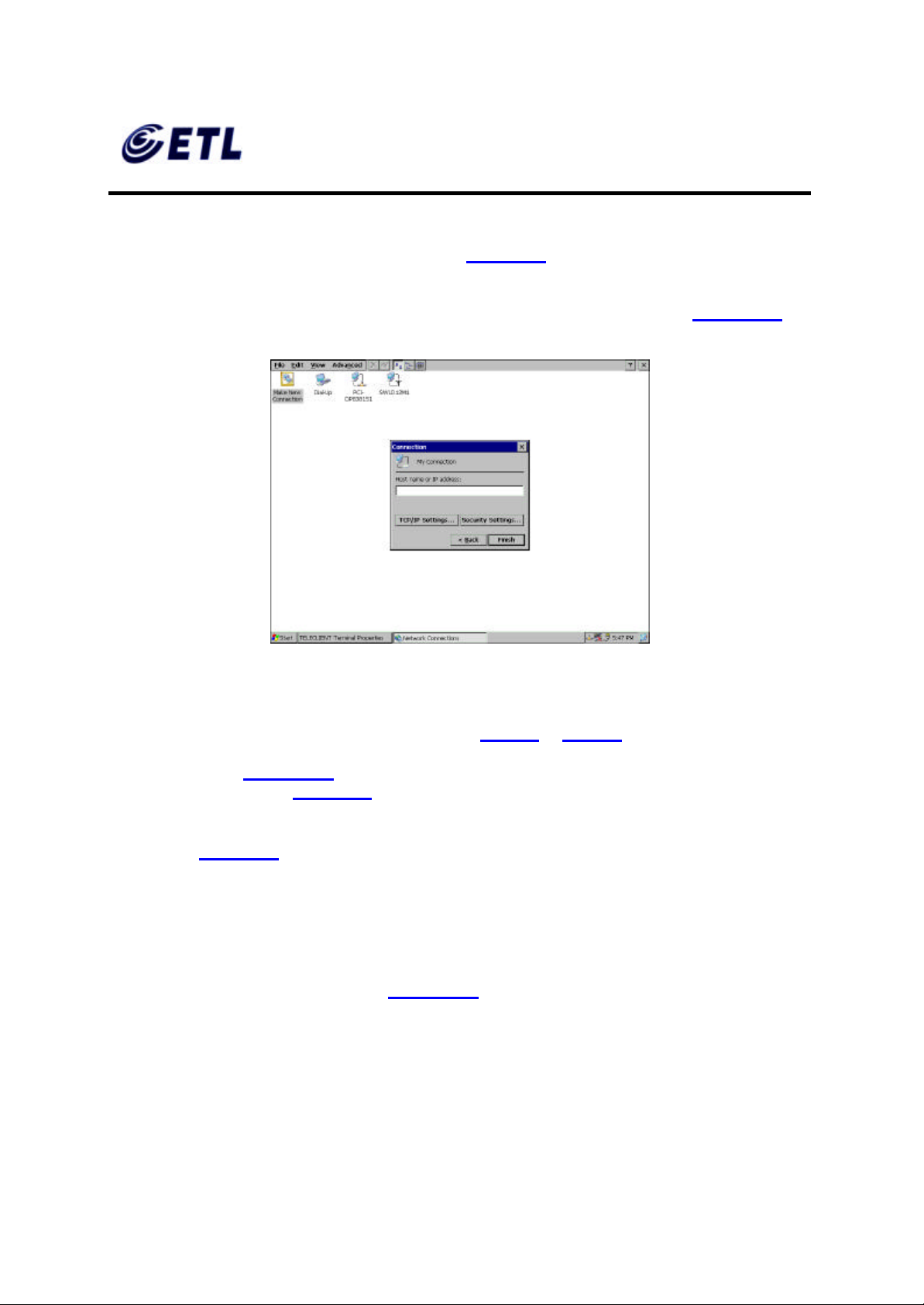
47. Back on the Network Properties screen (Figure 4.3), to create a VPN Connection,
double click on Make New Connection icon.
48. Type in the connection name, select VPN Connection, and click Next (Figure 4.21 ).
Figure 4.21 VPN Settings
49. Type in the host name or IP address in the box.
50. Click the TCP/IP Settings button and follow step 34 to step 40.
51. Click Finish (Figure 4.21). A new connection icon should appear on the Network
Properties screen (Figure 4.3).
52. Click X to close the window and the screen should return to WBT Setup Wizard
screen (Figure 4.2).
53. Click Next to continue setting up the terminal.
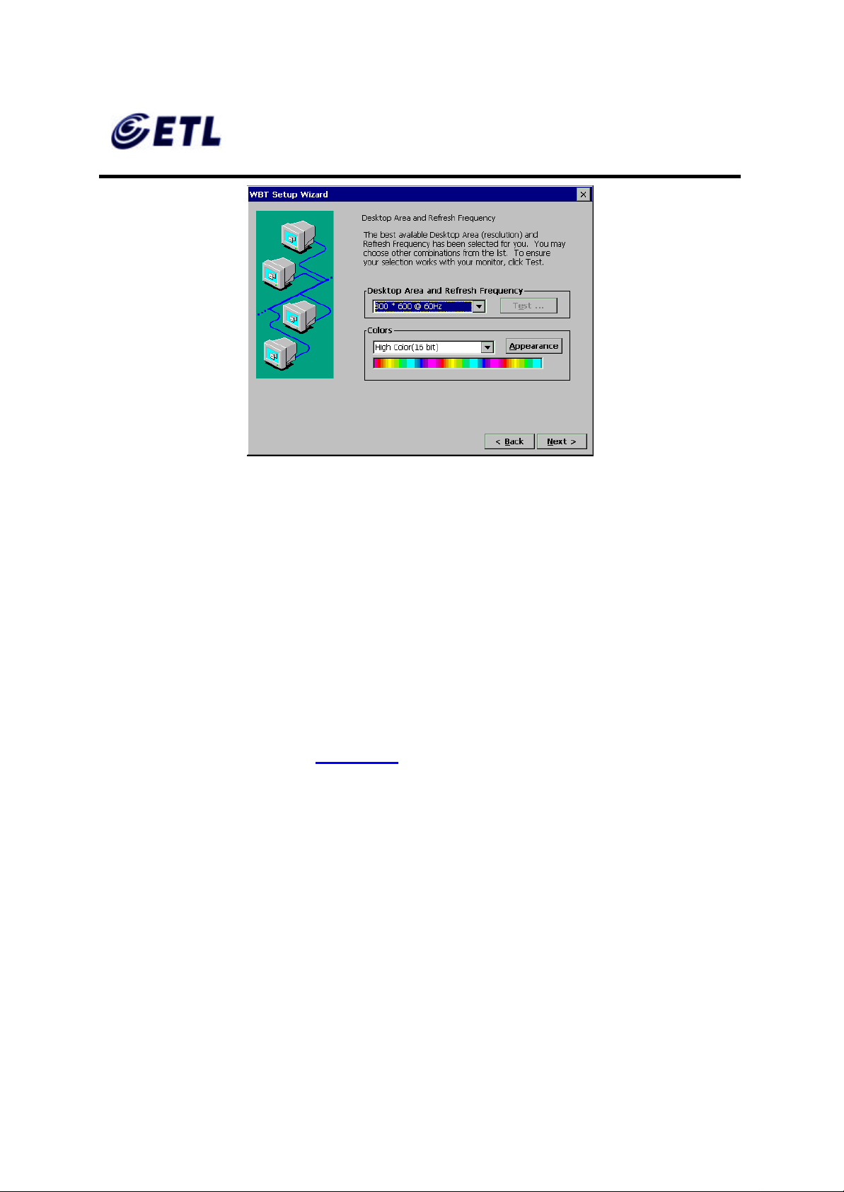
4.1.2. Display Setting
54. Display setting screen appears (Figure 4.22).
ETL Inc.
#584 Sangwhal -ri, Kanam-myon,
Yoju-kun, Kyounggi-do,
469-885, Korea 31 o 83f
17” Web Base Terminal
Model: TC7730
Page 32
FCC ID : PFMTC7730
GEMPACK CO., LTD.
Report No :E03.0718.FCC.404N
Issue of Date : July 18, 2003
Appendix F. Users Manual
Figure 4.22 Display Settings
55. For standard TeleCLIENT TC7730, there is only one resolution setting, 1024 x 768
@ 60Hz, but for the models with analog- digital converters have more resolutions to
choose from. Select a resol ution and color settings.
56. For AD -converter models, Select a Resolution and Refresh Frequency setting.
Click Test to see if the setting works.
57. When prompt for 5 seconds delay click OK to proceed.
58. If the chosen setting is accepted click Yes to confirm the setting. It will take effect
after the unit reboots.
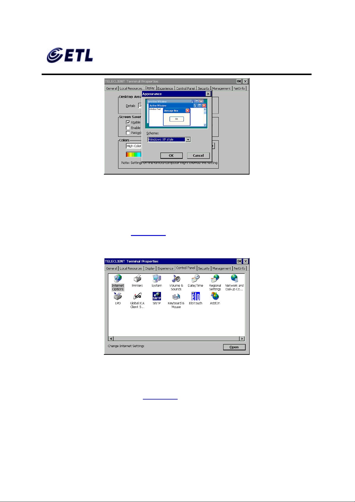
59. Choose Color settings.
60. Click Appearance button (Figure 4.23), and select either Windows Classic Style or
the new Windows XP style, then click OK.
ETL Inc.
#584 Sangwhal -ri, Kanam-myon,
Yoju-kun, Kyounggi-do,
469-885, Korea 32 o 83f
17” Web Base Terminal
Model: TC7730
Page 33
FCC ID : PFMTC7730
GEMPACK CO., LTD.
Appendix F. Users Manual
Figure 4.23 Desktop Appearance Set tings
61. Click Next to continue setting up the terminal.
4.1.3. Control Panel
Report No :E03.0718.FCC.404N
Issue of Date : July 18, 2003
Control Panel should appear ( Figure 4.24). Depends on the configuration and model,
the icons may appear differently.
Figure 4.24 Control Panel
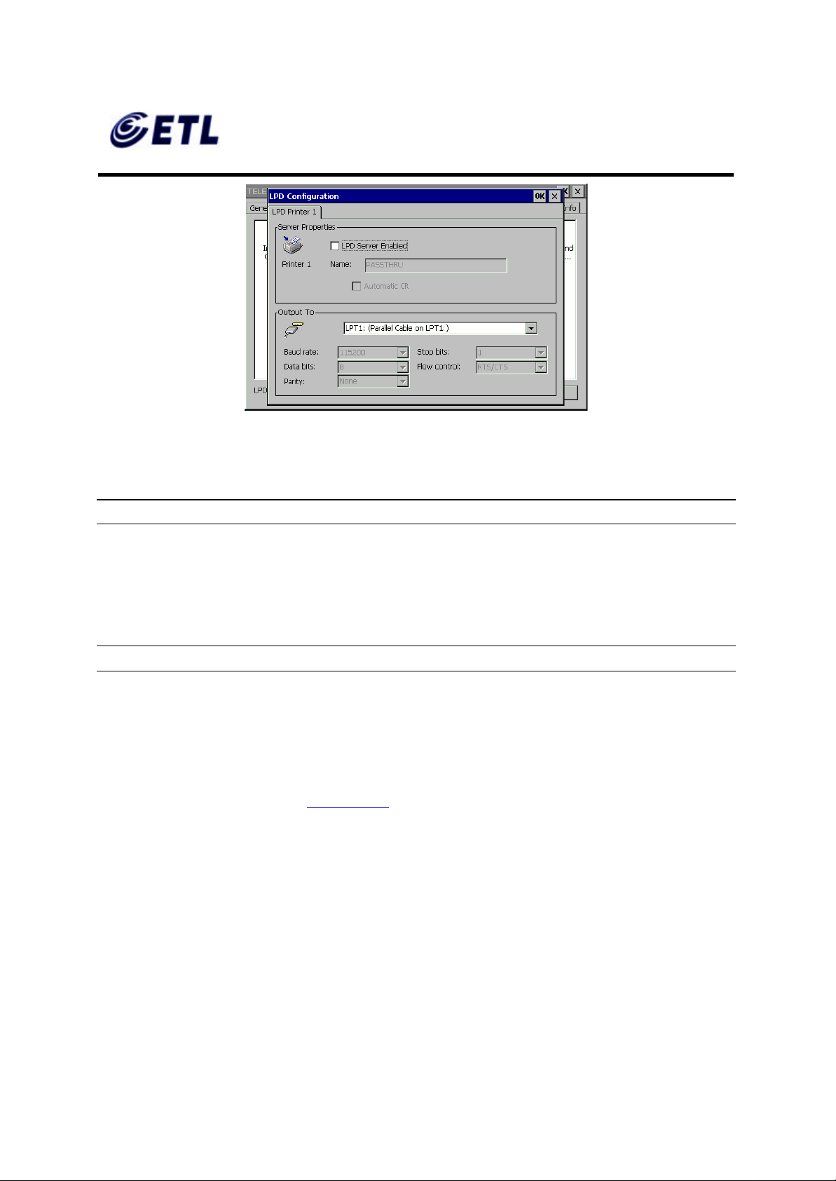
♦ LPD (Line Print Daemon) Printer Setup
62. Double click on the LPD icon (Figure 4.25).
ETL Inc.
#584 Sangwhal -ri, Kanam-myon,
Yoju-kun, Kyounggi-do,
469-885, Korea 33 o 83f
17” Web Base Terminal
Model: TC7730
Page 34
FCC ID : PFMTC7730
GEMPACK CO., LTD.
Report No :E03.0718.FCC.404N
Issue of Date : July 18, 2003
Appendix F. Users Manual
Figure 4.25 LPD Printing Setup
63. Check ‘LPD Server Enabled’ to enable LPD service.
NOTE: LPD CAN BE USED ONLY WITH THE LPT PORT OF A TELECLIENT.
64. Assign the printer name. The name of the printer is a virtual port. Virtual port is a
logical device assigned when you set up LPD services on your server. The default
for this field is PASSTHRU. The Printer Name is case sensitive field.
NOTE: THIS SERVICE W ILL NOT WORK IF THINPRINT IS BEING USED.
65. Click OK to confirm.
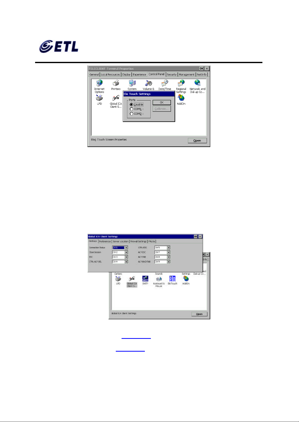
♦ Elo Touchscreen Setup
66. Double click the Elo icon (Figure 4.26).
ETL Inc.
#584 Sangwhal -ri, Kanam-myon,
Yoju-kun, Kyounggi-do,
469-885, Korea 34 o 83f
17” Web Base Terminal
Model: TC7730
Page 35
FCC ID : PFMTC7730
GEMPACK CO., LTD.
Appendix F. Users Manual
Figure 4.26 Elo Touchscreen Setup
67. TeleCLIENT TC7730T uses COM2 by default.
68. Click Calibrate.
Report No :E03.0718.FCC.404N
Issue of Date : July 18, 2003
69. Follow the on-screen instruction then click OK.
♦ Global ICA Client Setup
70. Double click the Global ICA Client Settings icon
Figure 4.27 Global ICA Client Setup
71. Setup the Hotkeys as desired ( Figure 4.27).
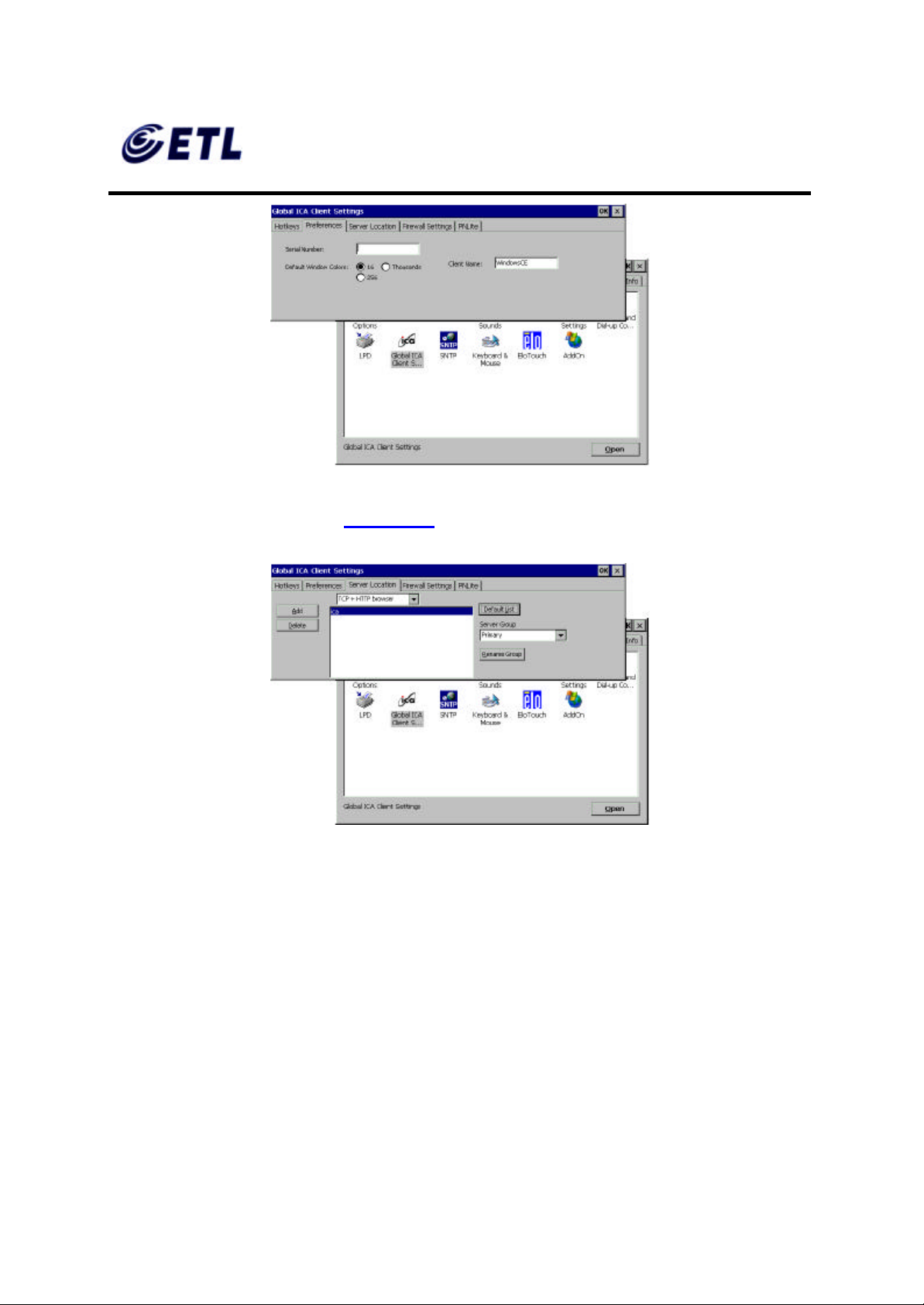
72. Click on the Preference tab (Figure 4.28 ). If desired type in the serial number of the
terminal and the terminal name or leave the default name on. Select a desired color
settings then click on the next tab.
ETL Inc.
#584 Sangwhal -ri, Kanam-myon,
Yoju-kun, Kyounggi-do,
469-885, Korea 35 o 83f
17” Web Base Terminal
Model: TC7730
Page 36
FCC ID : PFMTC7730
GEMPACK CO., LTD.
Appendix F. Users Manual
Figure 4.28 Global ICA Client Settings- Preference Tab
73. On the server location tab (Figure 4.29),
Report No :E03.0718.FCC.404N
Issue of Date : July 18, 2003
74. First choose the browser type. This will decide what type of servers should be
75. Click Default List button to list available servers. This will display a warning
76. If no server was detected click Add button to add a server to the list.
77. Select the type of the server group, and rename the group if desired. To rename,
78. A server name may be deleted from the list: Highlight the server to be deleted and
Figure 4.29 Global ICA Client Settings-Server Location Tab
detected.
message that the current list will be erased. Click Yes to proceed.
click on the Rename Group button and click OK.
click Delete button. When prompt click Yes to confirm.
ETL Inc.
#584 Sangwhal -ri, Kanam-myon,
Yoju-kun, Kyounggi-do,
469-885, Korea 36 o 83f
17” Web Base Terminal
Model: TC7730
Page 37
FCC ID : PFMTC7730
GEMPACK CO., LTD.
Report No :E03.0718.FCC.404N
Issue of Date : July 18, 2003
Appendix F. Users Manual
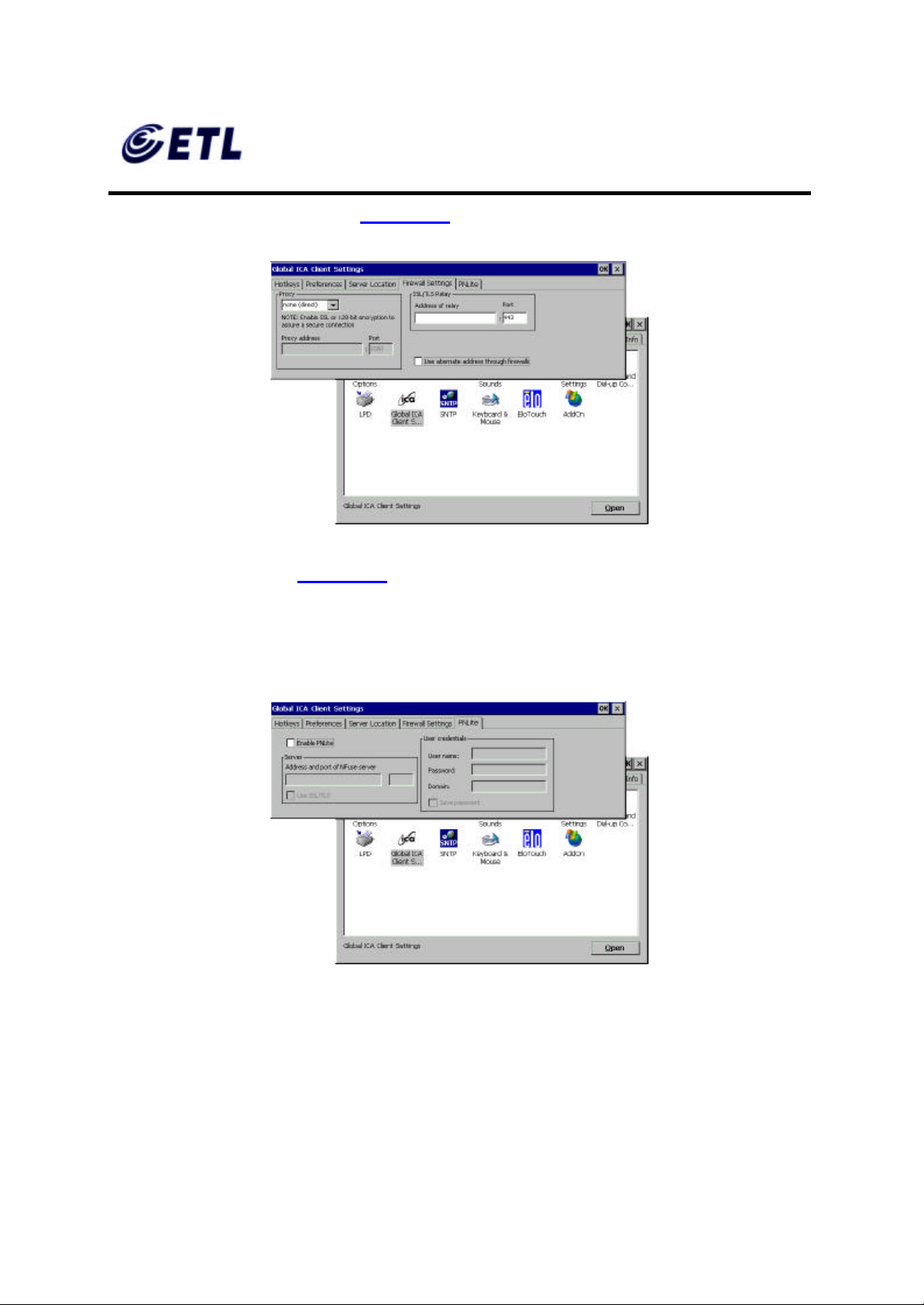
79. On the Firewall Settings tab (Figure 4.30 ),
Figure 4.30 Global ICA Client Settings-Firewall Settings Tab
80. Click on PNLite tab (Figure 4.31 ). PNLite is a feature that allows the client to
connect via Citrix NFuse without a local web browser. It can obtain connection
information for a particular user from an NFuse server and add those connections to
the normal WBT list of connections, as if they’d been added by hand using the local
UI.
81. To use PNLite feature, check the ‘Enable PNLite ’ box, type in the server
82. Click OK.
Figure 4.31 Global ICA Client Settings-PNLite Settings Tab
information, and fil l in the User Credential information.
ETL Inc.
#584 Sangwhal -ri, Kanam-myon,
Yoju-kun, Kyounggi-do,
469-885, Korea 37 o 83f
17” Web Base Terminal
Model: TC7730
Page 38
FCC ID : PFMTC7730
GEMPACK CO., LTD.
Appendix F. Users Manual
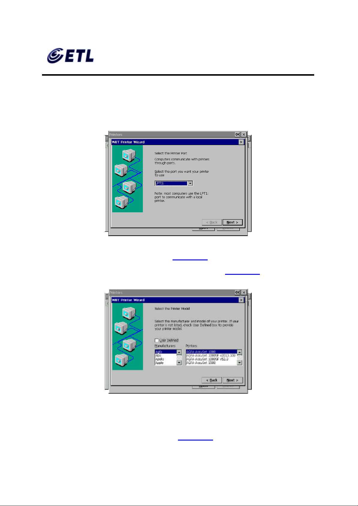
♦ Printer Setup
83. Double click on Printers icon.
84. Double click on Add Printer icon.
Report No :E03.0718.FCC.404N
Issue of Date : July 18, 2003
Figure 4.32 Printer Setup – Port Selection
85. Select a port the printer is connected to( Figure 4.32).
86. Select Manufacture of the printer and the Model Name (Figure 4.33 ).
Figure 4.33 Printer Setup – Manufacturer and Model
87. If the desired manufacturer and model is not listed check the User Defined box.
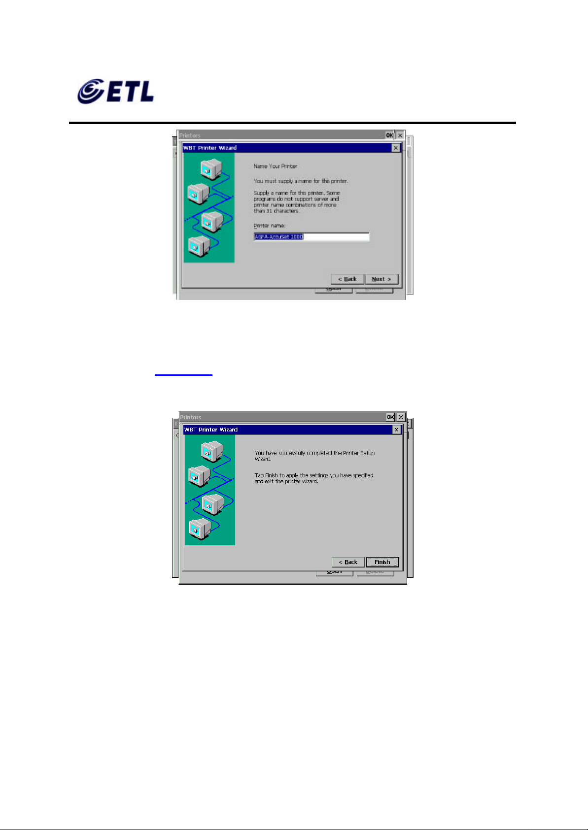
88. Type in the Printer Name, then click Next (Figure 4.34).
Click Next, and type in the manufacturer and t he model name, and then click Next .
ETL Inc.
#584 Sangwhal -ri, Kanam-myon,
Yoju-kun, Kyounggi-do,
469-885, Korea 38 o 83f
17” Web Base Terminal
Model: TC7730
Page 39
FCC ID : PFMTC7730
GEMPACK CO., LTD.
Report No :E03.0718.FCC.404N
Issue of Date : July 18, 2003
Appendix F. Users Manual
Figure 4.34 Printer Setup – Printer Name
89. If there are more printers to be added check Yes and click Next. Otherwise, check
No and click Next.
90. Click Finish (Figure 4.35). The new printer icon should appear on the Printers
screen. Click OK.
Figure 4.35 Printer Setup – Finish
91. To delete a printer, simply highlight the printer and click Delete button.
♦ Internet Options (Only on TC7730W Series)
92. Double click on Internet Options.
ETL Inc.
#584 Sangwhal -ri, Kanam-myon,
Yoju-kun, Kyounggi-do,
469-885, Korea 39 o 83f
17” Web Base Terminal
Model: TC7730
Page 40
FCC ID : PFMTC7730
GEMPACK CO., LTD.
Report No :E03.0718.FCC.404N
Issue of Date : July 18, 2003
Appendix F. Users Manual
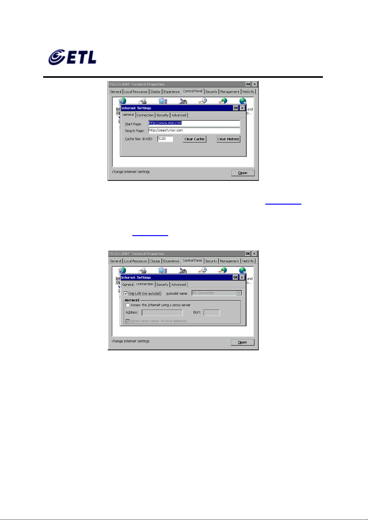
Figure 4.36 Internet Options
93. Type in the Start Page and Search Page, or leave the default URL (Figure 4.36).
94. Set the Cache size or leave the default value (recommended).
95. Click on Connection tab (Figure 4.37 ).
Figure 4.37 Internet Options - Connection
96. Check ‘Use LAN (no autodial)’ box if using LAN. Otherwise, uncheck the box and
type in the Autodial name.
97. If the terminal is connected through a proxy server check ‘Access the Internet
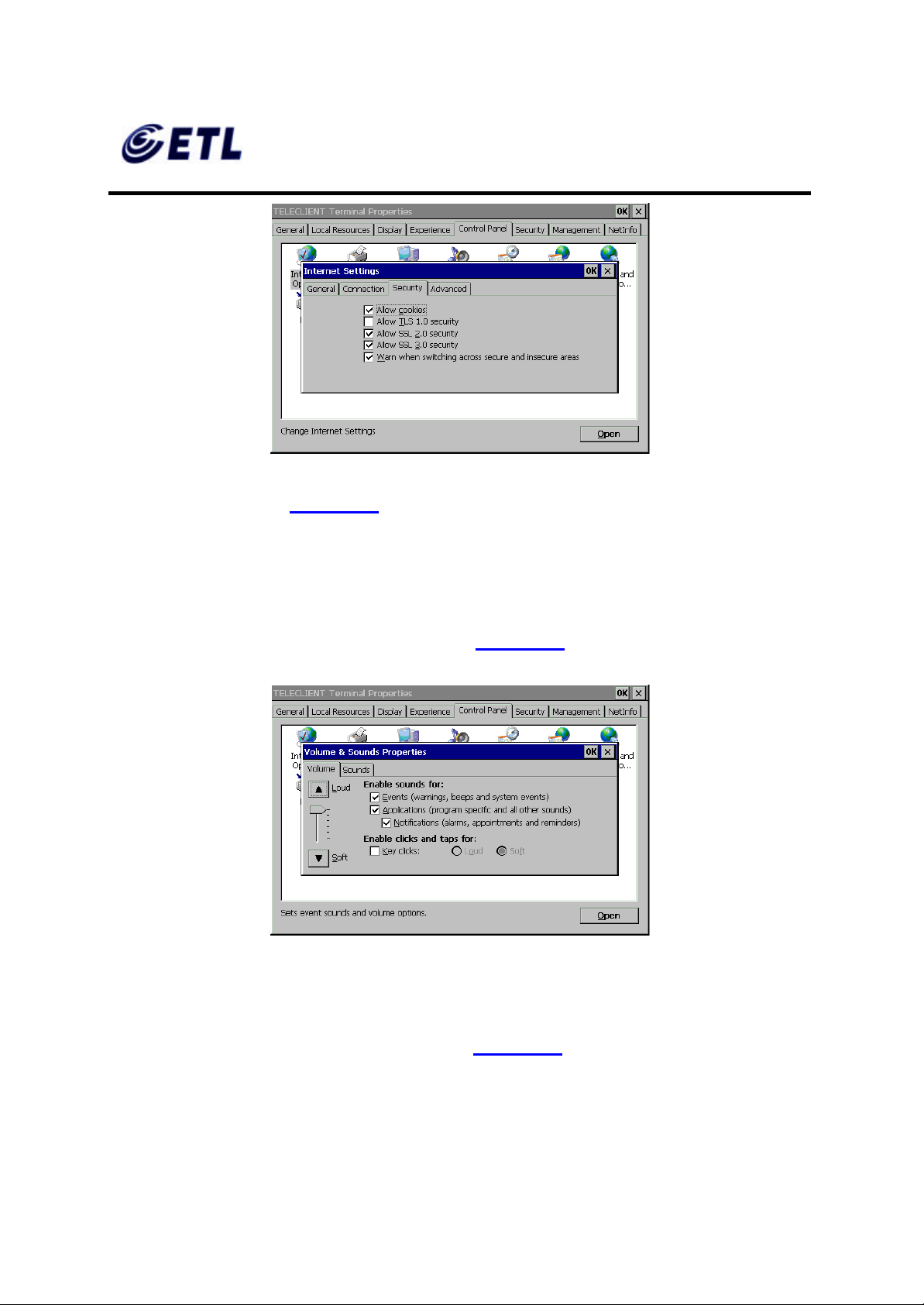
using a proxy server’ and type in the necessary information. Then click OK.
98. On Security tab, check all the security options then click OK.
ETL Inc.
#584 Sangwhal -ri, Kanam-myon,
Yoju-kun, Kyounggi-do,
469-885, Korea 40 o 83f
17” Web Base Terminal
Model: TC7730
Page 41
FCC ID : PFMTC7730
GEMPACK CO., LTD.
Appendix F. Users Manual
Figure 4.38 Internet Options - Security
99. On Advanced tab (Figure 4.38 ).
100. Select desired options then click OK.
Report No :E03.0718.FCC.404N
Issue of Date : July 18, 2003
♦ Volume and Sounds Setup
101. Double click on Volume & Sounds icon (Figure 4.39 )
Figure 4.39 Volume and Sounds
102. Choose options as shown on the window, set the system volume at a desired
level, and then click on Sounds tab.
103. Choose a sound scheme and click OK (Figure 4.40 ).
ETL Inc.
#584 Sangwhal -ri, Kanam-myon,
Yoju-kun, Kyounggi-do,
469-885, Korea 41 o 83f
17” Web Base Terminal
Model: TC7730
Page 42
FCC ID : PFMTC7730
GEMPACK CO., LTD.
Appendix F. Users Manual
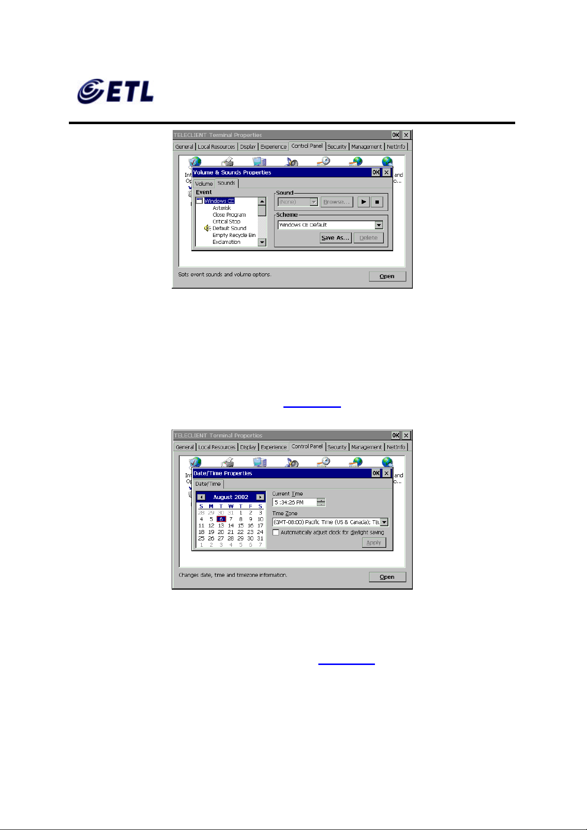
Figure 4.40 Sound Scheme
♦ Date and Time Setup
Report No :E03.0718.FCC.404N
Issue of Date : July 18, 2003
104. Double click on the Date/Time icon.
105. Set the date and time then click OK (Figure 4.41).
Figure 4.41 Date and Time
♦ Regional Settings
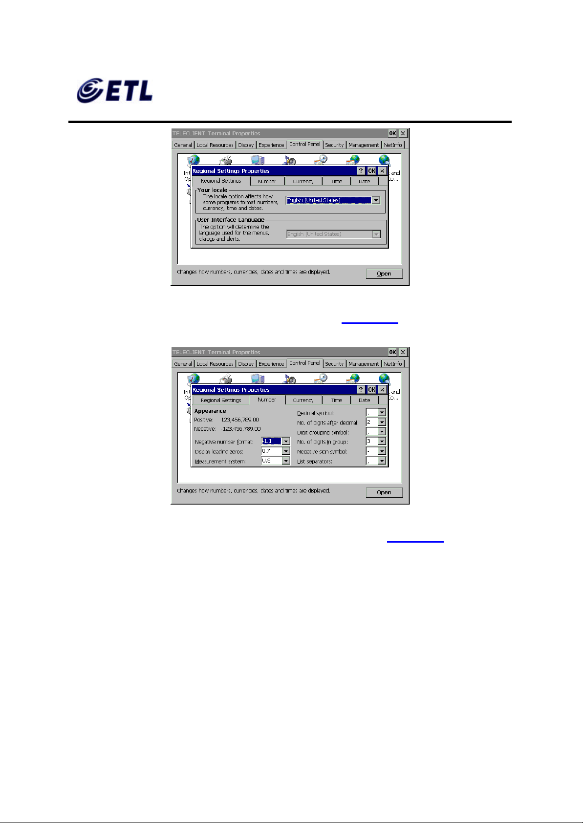
106. Double click on the Regional Settings icon (Figure 4.42 ).
ETL Inc.
#584 Sangwhal -ri, Kanam-myon,
Yoju-kun, Kyounggi-do,
469-885, Korea 42 o 83f
17” Web Base Terminal
Model: TC7730
Page 43
FCC ID : PFMTC7730
GEMPACK CO., LTD.
Report No :E03.0718.FCC.404N
Issue of Date : July 18, 2003
Appendix F. Users Manual
Figure 4.42 Regional Settings - Locale
107. Select locale and click on the next tab, Number (Figure 4.43 ).
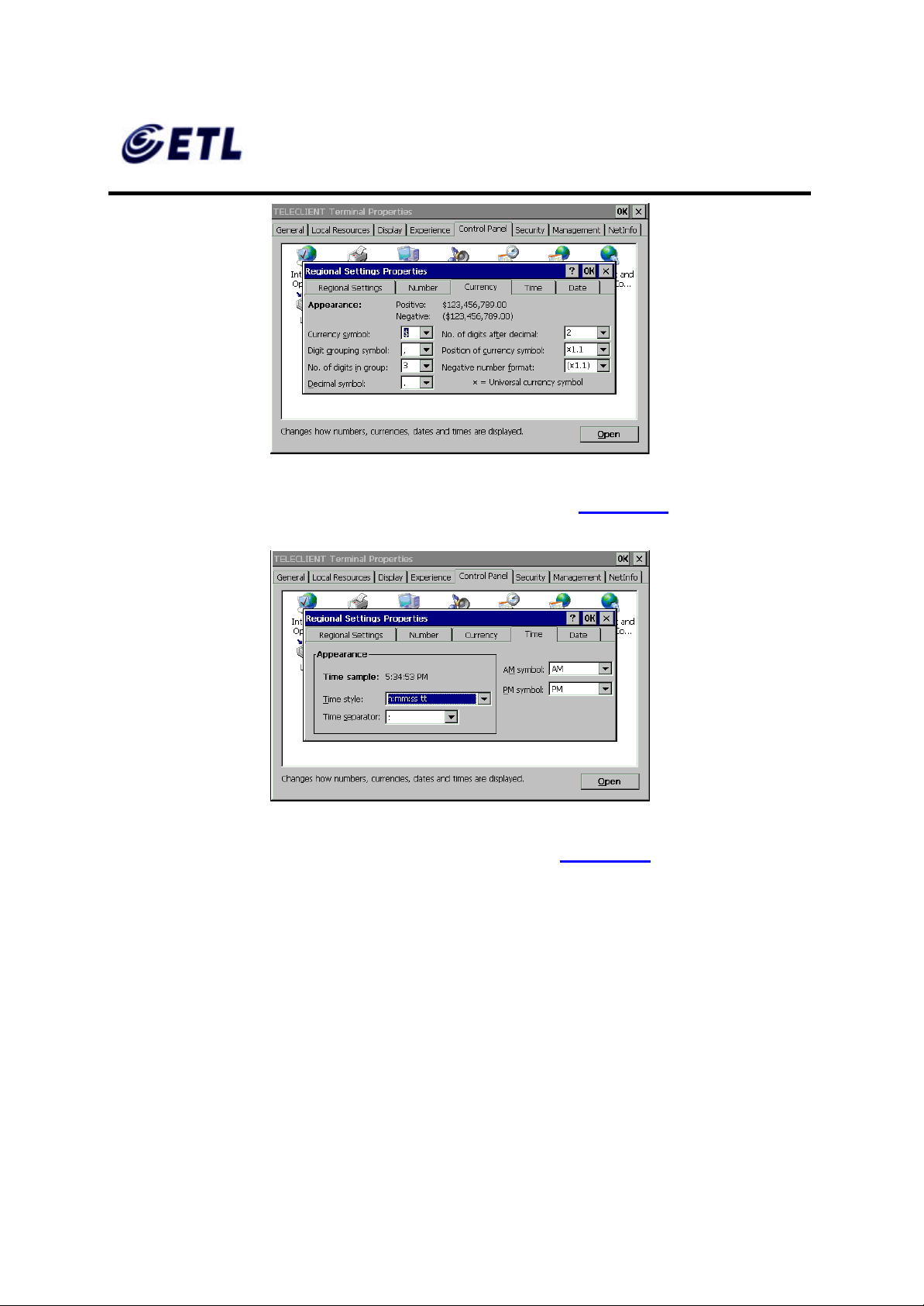
108. Select number systems then click the next tab, Currency (Figure 4.44 ).
Figure 4.43 Regional Settings - Number
ETL Inc.
#584 Sangwhal -ri, Kanam-myon,
Yoju-kun, Kyounggi-do,
469-885, Korea 43 o 83f
17” Web Base Terminal
Model: TC7730
Page 44
FCC ID : PFMTC7730
GEMPACK CO., LTD.
Report No :E03.0718.FCC.404N
Issue of Date : July 18, 2003
Appendix F. Users Manual
Figure 4.44 Regional Settings - Currency
109. Select currency settings then click the next tab, Time (Figure 4.45 ).
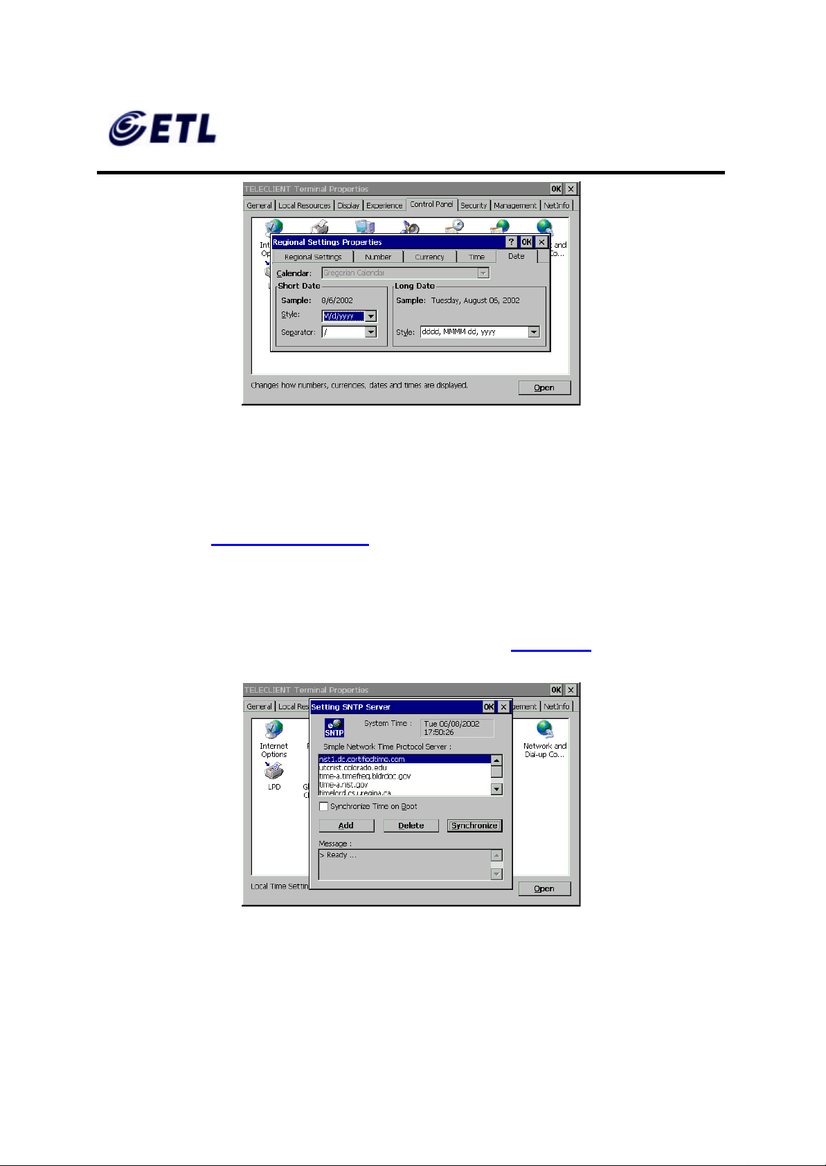
110. Select the time format then click the next tab, Date (Figure 4.46).
Figure 4.45 Regional Settings - Time
ETL Inc.
#584 Sangwhal -ri, Kanam-myon,
Yoju-kun, Kyounggi-do,
469-885, Korea 44 o 83f
17” Web Base Terminal
Model: TC7730
Page 45
FCC ID : PFMTC7730
GEMPACK CO., LTD.
Appendix F. Users Manual
Figure 4.46 Regional Settings - Date
111. Select the date format then click OK.
♦ Network and Dial -up Connections
Report No :E03.0718.FCC.404N
Issue of Date : July 18, 2003
Refer to section 1.1.1 Network Settings.
♦ SNTP Settings
112. SNTP is a Simple Network Time Protocol. It allows the terminal to synchronize
time with available time-servers on Wide Area Network (Figure 4.47 ).
Figure 4.47 SNTP Settings
113. Select any of the displayed time-server then click Synchronize.
114. Unlisted time-server can be added as well. Click Add then type in the server IP
address or the host name.
ETL Inc.
#584 Sangwhal -ri, Kanam-myon,
Yoju-kun, Kyounggi-do,
469-885, Korea 45 o 83f
17” Web Base Terminal
Model: TC7730
Page 46
FCC ID : PFMTC7730
GEMPACK CO., LTD.
Appendix F. Users Manual
115. Click OK.
♦ Keyboard and Mouse Setup
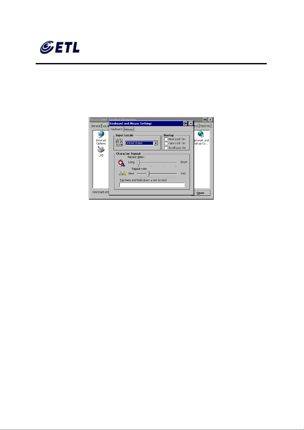
116. Double click on Keyboard and Mouse (Figure 4.48).
Report No :E03.0718.FCC.404N
Issue of Date : July 18, 2003
Figure 4.48 Keyboard
117. This section changes the following keyboard characteristics to match the user’s
own keyboard and typing habits:
• Keyboard Locale - The language used by the keyboard.
• Character Repeat - The repeat delay of a keyboard character (i.e., length of time
elapsed before a character is repeated when a key is pressed).
• Repeat Rate - The rate at which the keyboard repeats characters.
• Num Lock On/Off at Boot -up option
• Cap Lock On/Off at Boot -up option
• Scroll Lock On/Off at Boot -up option
118. Select Left-handed or Right-handed mouse, select the pointer speed then
click OK.
♦ Power Button Control
119. Double click on Button Control icon.
ETL Inc.
#584 Sangwhal -ri, Kanam-myon,
Yoju-kun, Kyounggi-do,
469-885, Korea 46 o 83f
17” Web Base Terminal
Model: TC7730
Page 47

FCC ID : PFMTC7730
GEMPACK CO., LTD.
Report No :E03.0718.FCC.404N
Issue of Date : July 18, 2003
Appendix F. Users Manual
120. Select Instant Power Off or 4 Seconds Delay power button option.
121. To disable the power button, simply check the option box and click OK.
Click Next to proceed with the WBT Setup Wizard.
Click Finish to complete the setup. You are now ready to create network connections
and connect to the network.
ETL Inc.
#584 Sangwhal -ri, Kanam-myon,
Yoju-kun, Kyounggi-do,
469-885, Korea 47 o 83f
17” Web Base Terminal
Model: TC7730
Page 48

FCC ID : PFMTC7730
GEMPACK CO., LTD.
Report No :E03.0718.FCC.404N
Issue of Date : July 18, 2003
Appendix F. Users Manual
4.2. Setting TeleCLIENT TC7730 Properties
All terminal properties can be modified in TeleCLIENT Terminal Properties window.
NOTE: WHEN MAKING CHANGES IN THE TELECLIENT TERMINAL PROPERTIES
WINDOW, CLICK OK TO SET THE NEW VALUES, AND CLICK X AT ANY TIME TO
CANCEL AND RETURN TO THE TELECLIENT CONNECTION MANAGER WINDOW.
The TeleCLIENT Terminal Properties window includes the following tabs:
• General
Displays product, copyright information, terminal name, and resets the terminal to
factory defaults.
• Local Resource
Configure sound control and peripheral devices.
• Display
Configure display settings, screen saver, and desktop appearance.
Experience
•
Configure network connection speed, start up delay setting (searching for
networks), and miscellaneous settings.
• Control Panel
Configure the Internet options, touchscreen, printers, Global ICA settings, system
information, volume and sounds, date/time, regional settings, network and dial -up
settings, SNTP, keyboard and mouse, add-on devices, and power button control.
• Security
Configure various security settings.
• Management
Configure SNMP agent, and update software and firmware.
• NetInfo
Display the network status, and provides Ping function.
ETL Inc.
#584 Sangwhal -ri, Kanam-myon,
Yoju-kun, Kyounggi-do,
469-885, Korea 48 o 83f
17” Web Base Terminal
Model: TC7730
Page 49
FCC ID : PFMTC7730
GEMPACK CO., LTD.
Report No :E03.0718.FCC.404N
Issue of Date : July 18, 2003
Appendix F. Users Manual
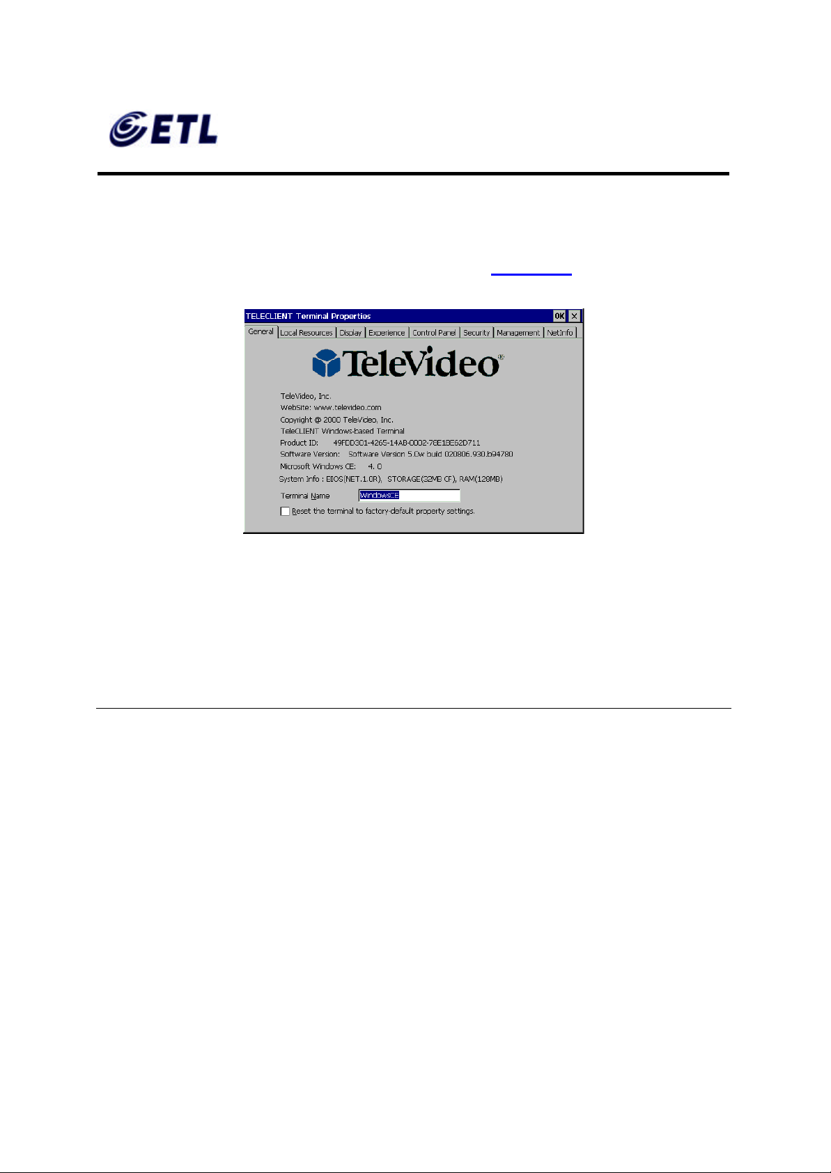
4.2.1. General Tab
To start the TeleCLIENT Terminal Properties, while the TeleCLIENT Connection
Manager is displayed, Press < F2> on the TeleCLIENT TC7730 keyboard. The
TeleCLIENT Terminal Properties window will appear (Figure 4.49 ).
Figure 4.49 TeleCLIENT Terminal Properties – General Tab
♦ To restore the factory default settings, complete the following steps:
1. Check the box, ‘Reset the terminal to factory-default property settings.’
2. Click Yes when prompt.
NOTE : WHEN YOU RESTART THE TELECLIENT TC7730 AFTER RESETTING THE
FACTORY DEFAULTS, YOU MUST USE THE SETUP WIZARD AGAIN. REFER TO
SECTION 1.1 - TELECLIENT SETUP WIZARD.
♦ Terminal Name
Assign the terminal name in the box or leave the default name, but DO NOT leave it
blank.
ETL Inc.
#584 Sangwhal -ri, Kanam-myon,
Yoju-kun, Kyounggi-do,
469-885, Korea 49 o 83f
17” Web Base Terminal
Model: TC7730
Page 50
FCC ID : PFMTC7730
GEMPACK CO., LTD.
Appendix F. Users Manual
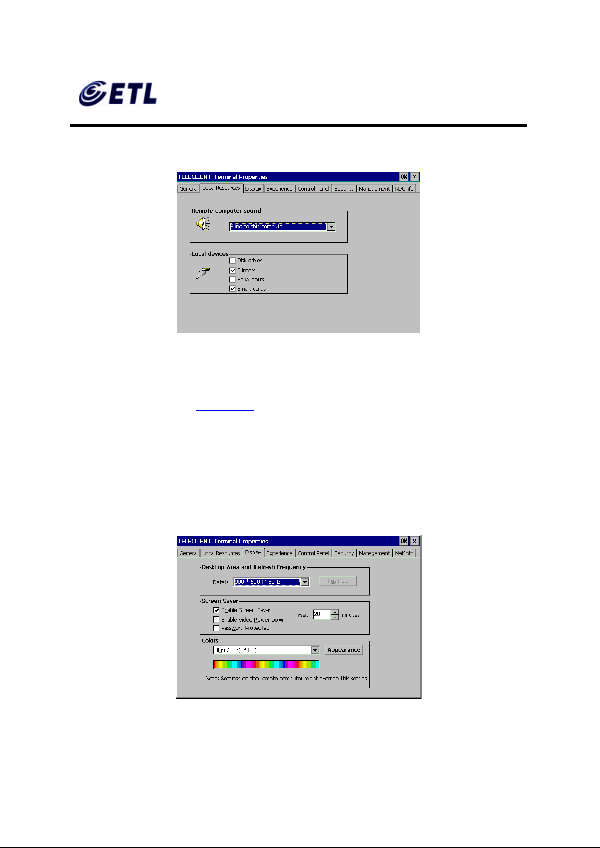
4.2.2. Local Resources Tab
Figure 4.50 Local Resources
Report No :E03.0718.FCC.404N
Issue of Date : July 18, 2003
♦ Sound Option
Select the sound option ( Figure 4.50).
♦ Local Devices
Check all the devices attached to the terminal to enable them.
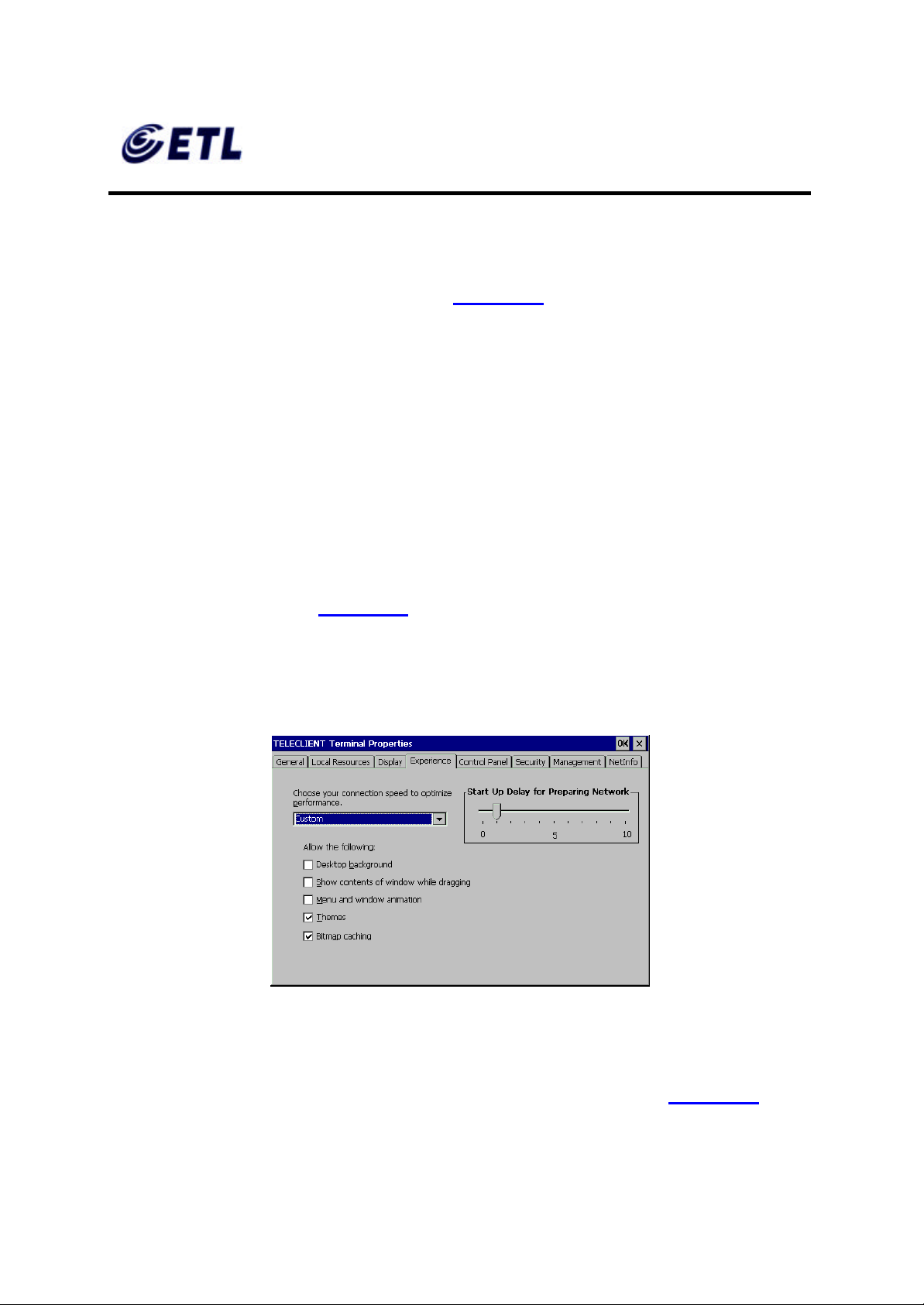
4.2.3. Display Tab
Figure 4.51 Display
ETL Inc.
#584 Sangwhal -ri, Kanam-myon,
Yoju-kun, Kyounggi-do,
469-885, Korea 50 o 83f
17” Web Base Terminal
Model: TC7730
Page 51
FCC ID : PFMTC7730
GEMPACK CO., LTD.
Report No :E03.0718.FCC.404N
Issue of Date : July 18, 2003
Appendix F. Users Manual
♦ Display Area and Refresh Frequency
For standard TeleCLIENT TC7730, there is only one resolution setting, 1024 x 768 @
60Hz, but for the models with analog -digital converters have more resolutions to choose
from. Select a resolution and color settings ( Figure 4.51).
♦ Screen Saver
1. To enable Screen Saver, check the box, and set the duration of No-Activity in
minutes before the Screen Saver starts.
2. Check the box, ‘Enable Video Power Down’ if desired in addition to Screen Saver.
3. Check the box, ‘ Password Pr otected’, to set a password protection upon recovery
form the Screen Saver mode.
♦ Colors and Appearance
Click Appearance button (Figure 4.51), and select either Windows Classic Style or the
new Windows XP style, then click OK.
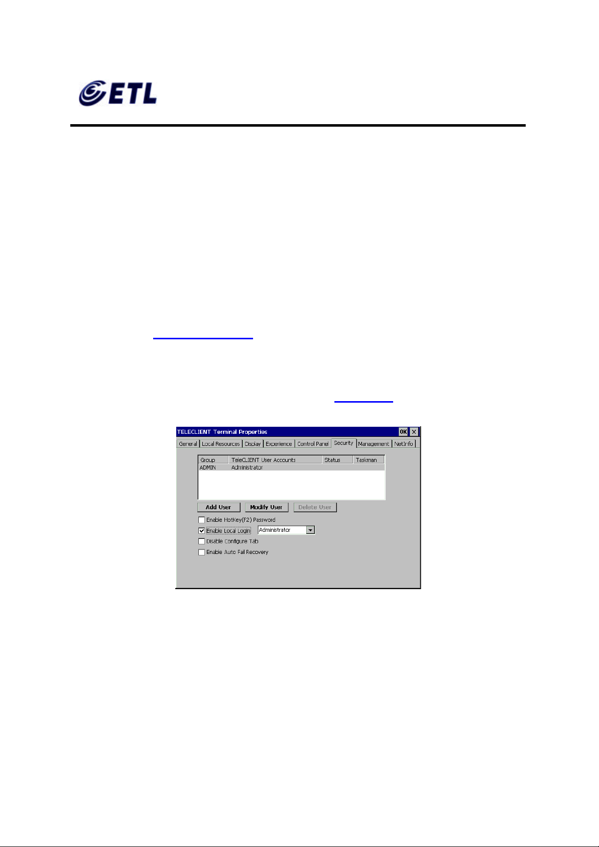
4.2.4. Experience Tab
Figure 4.52 Experience
♦ Network Connection Speed
Select the network connection speed to optimize the terminal operation ( Figure 4.52).
ETL Inc.
#584 Sangwhal -ri, Kanam-myon,
Yoju-kun, Kyounggi-do,
469-885, Korea 51 o 83f
17” Web Base Terminal
Model: TC7730
Page 52
FCC ID : PFMTC7730
GEMPACK CO., LTD.
Report No :E03.0718.FCC.404N
Issue of Date : July 18, 2003
Appendix F. Users Manual
♦ Desktop Properties
Select the options to be enabled on the desktop during RDP sessions.
♦ Start Up Delay for Preparing Network
Set this delay time according to the tendency of the network status. In a normally
congested network will require more time to establish network communications, and in a
network with less traffic will require less tim e to establish network communications.
Setting this too low may cause some difficulty establishing network communications.
4.2.5. Control Panel Tab
Refer to section 1.1.3, Control Panel.
4.2.6. Security Tab
This section sets up securit y on the terminal access (Figure 4.53).
Figure 4.53 Security
♦ Adding User
1. To add a user to the list of permitted users, click Add User button.
ETL Inc.
#584 Sangwhal -ri, Kanam-myon,
Yoju-kun, Kyounggi-do,
469-885, Korea 52 o 83f
17” Web Base Terminal
Model: TC7730
Page 53
FCC ID : PFMTC7730
GEMPACK CO., LTD.
Appendix F. Users Manual
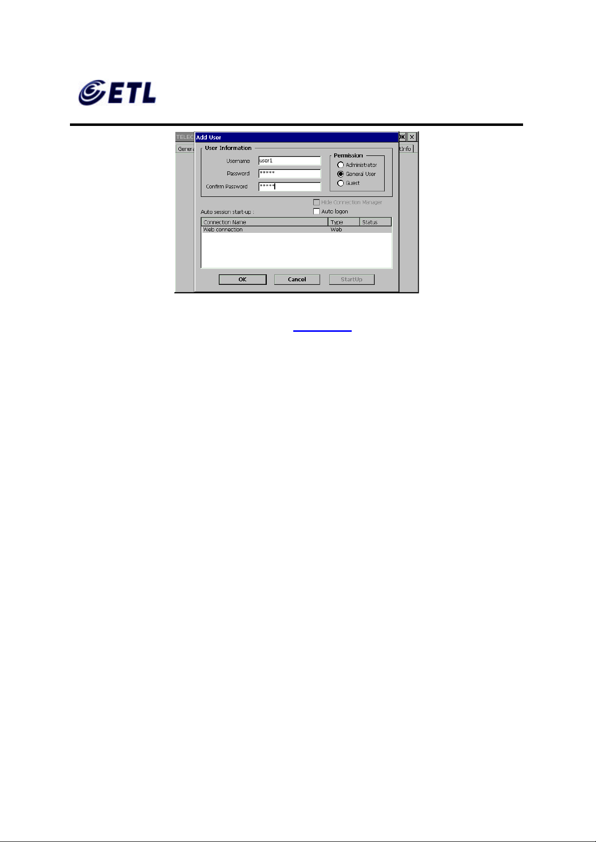
Figure 4.54 Security-Add User
2. Type in the User Name and Password (Figure 4.54).
3. Select the Permission level.
Report No :E03.0718.FCC.404N
Issue of Date : July 18, 2003
4. Check the box, ‘ Auto logon’, if the user should be logon to a session highlighted in
the box below.
5. To bypass the connection manager screen on startup, click on StartUp button, and
check the box, ‘Hide Connection Manger’ .
6. Use Modify User button to edit these settings after this initial setup, and Delete
User button to delete a user.
7. Click OK.
♦ Terminal Properties Window Protection
Check the box, ‘ Enable HotKey (F2) Password’, to stop users from going into the
properties win dow.
♦ Enable Local Login
Check this box to limit the terminal usage to the permitted users.
♦ Disable Configure Tab
Check this box to stop users from going into the Connection Manager Configure tab
and making changes to session properties.
ETL Inc.
#584 Sangwhal -ri, Kanam-myon,
Yoju-kun, Kyounggi-do,
469-885, Korea 53 o 83f
17” Web Base Terminal
Model: TC7730
Page 54
FCC ID : PFMTC7730
GEMPACK CO., LTD.
Report No :E03.0718.FCC.404N
Issue of Date : July 18, 2003
Appendix F. Users Manual
♦ Enable Auto Fail Re covery
In an unexpected power down situation, this feature allows the users to automatically
log back on to the session.
♦ Hide Web Connection
Check this box to stop users from making changes to the Internet Configuration.
4.2.7. Management Tab
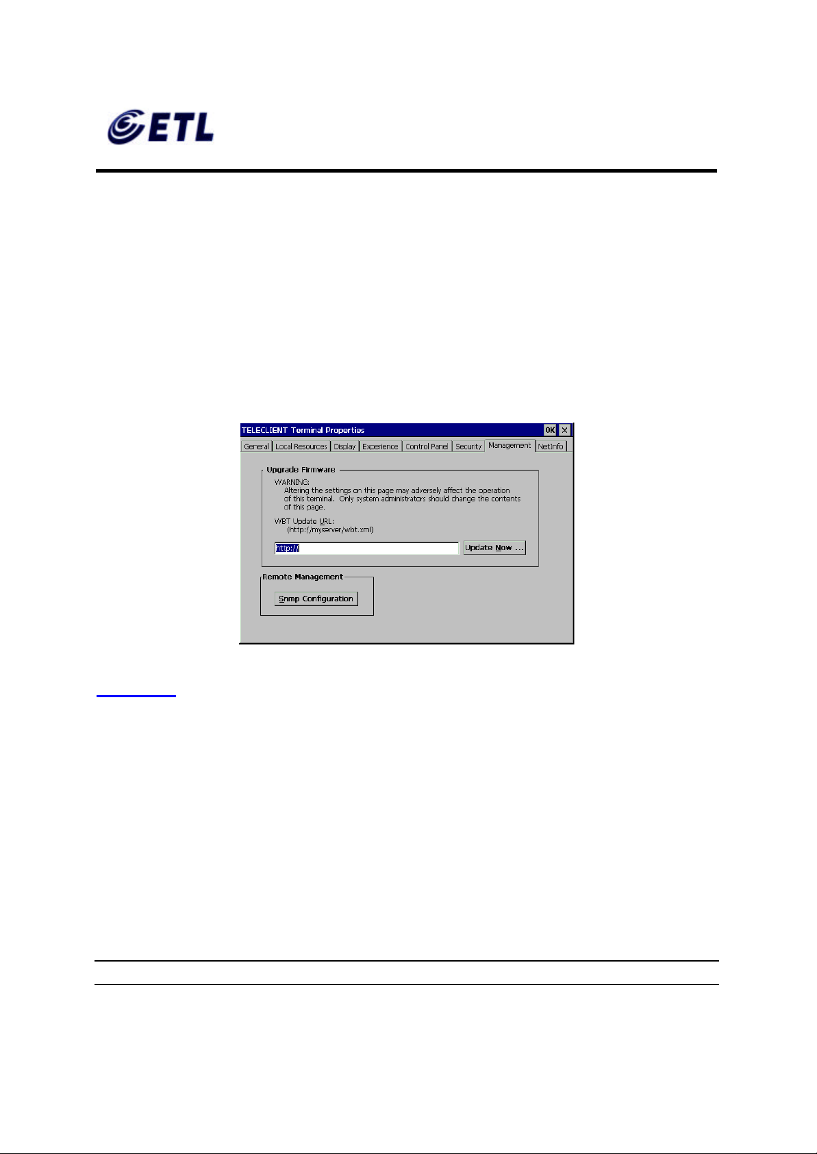
Figure 4.55 Management
Figure 4.55 illustrates the Management tab, which displays the support for TeleCLIENT
software update functionality. The property page components are as follows:
• Edit Box: Contains the Uniform Resource Locator (URL) for the update package
used by TeleCLIENT for software updates. Supported protocols are http:// and
ftp://.
• Update Now… button: Used to immediately perform a manual software update,
using the indicated URL.
• SNMP Configuration.
♦ Software/Firmware Update
NOTE: THIS WILL FORCE A RESET OF THE TERMINAL.
ETL Inc.
#584 Sangwhal -ri, Kanam-myon,
Yoju-kun, Kyounggi-do,
469-885, Korea 54 o 83f
17” Web Base Terminal
Model: TC7730
Page 55
FCC ID : PFMTC7730
GEMPACK CO., LTD.
Report No :E03.0718.FCC.404N
Issue of Date : July 18, 2003
Appendix F. Users Manual
To update the software/firmware of the terminal, type in the URL of the web server
containing the new image then click Update Now button.
NOTE: TO ENSURE CORR ECT IMAGE UPDATE, PLEASE VISIT
WWW.TELEVIDEO.COM OR CONTACT TELEVIDEO TECH SUPPORT.
♦ SNMP Configuration
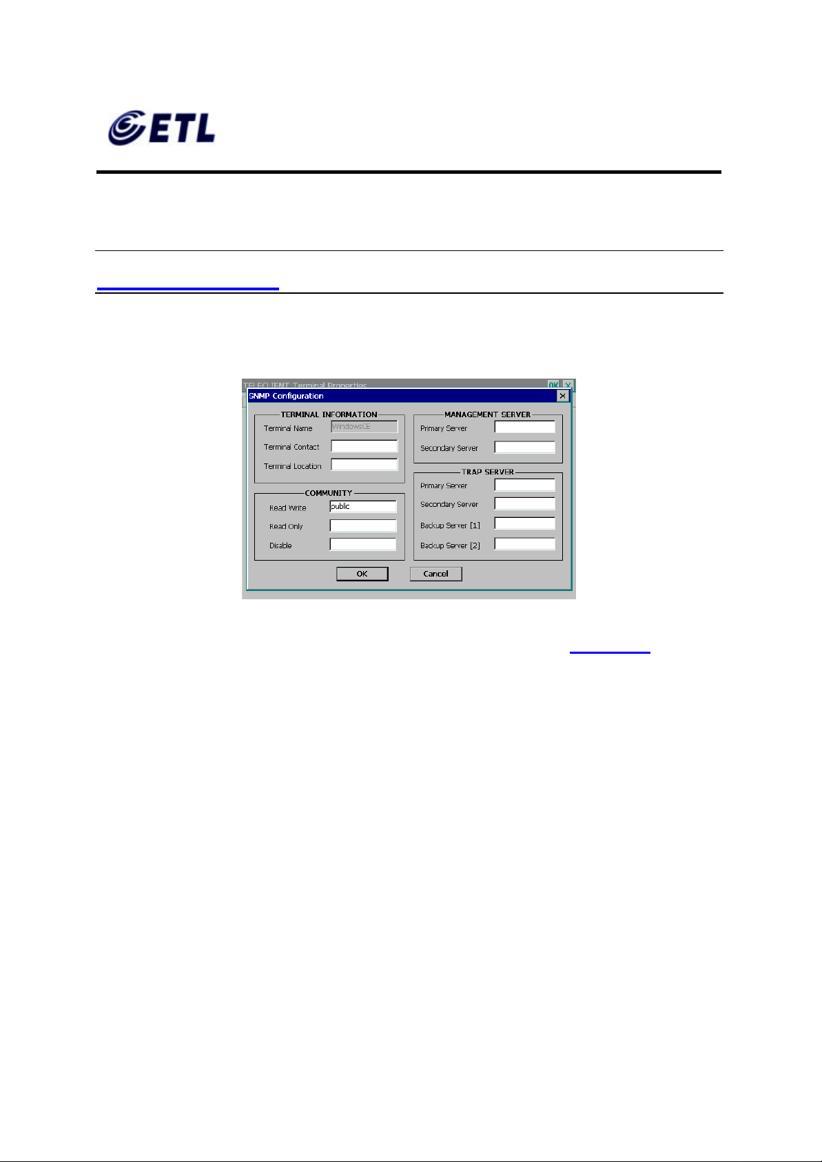
Figure 4.56 Management - SNMP
1. To configure SNMP settings, click SNMP Configuration button (Figure 4.56).
2. Enter the contact for the terminal (usually the user of the terminal) and the location.
3. Community section refers to the SNMP group definition. Enter the group name.
4. Enter all the necessary and appropriate server names in each category.
5. Click OK.
ETL Inc.
#584 Sangwhal -ri, Kanam-myon,
Yoju-kun, Kyounggi-do,
469-885, Korea 55 o 83f
17” Web Base Terminal
Model: TC7730
Page 56
FCC ID : PFMTC7730
GEMPACK CO., LTD.
Report No :E03.0718.FCC.404N
Issue of Date : July 18, 2003
Appendix F. Users Manual
4.2.8. Net-Info Tab
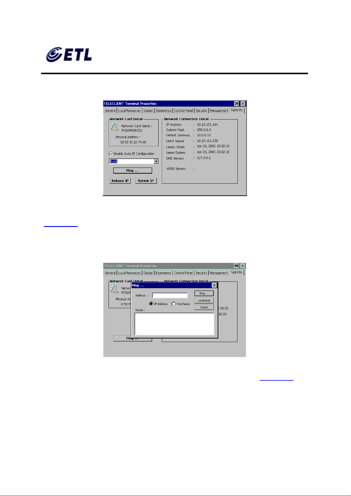
Figure 4.57 NetInfo
This tab displays the hardware address (MAC Address) and other Network information
(Figure 4.57 ).
♦ Ping
Figure 4.58 NetInfo – Ping
This command allows the administrator to check the network connections (Figure 4.58 ).
This completes the terminal pro perties setting. Please continue to the Operation
section of the manual to configure terminal service sessions.
ETL Inc.
#584 Sangwhal -ri, Kanam-myon,
Yoju-kun, Kyounggi-do,
469-885, Korea 56 o 83f
17” Web Base Terminal
Model: TC7730
Page 57

FCC ID : PFMTC7730
GEMPACK CO., LTD.
Report No :E03.0718.FCC.404N
Issue of Date : July 18, 2003
Appendix F. Users Manual
♦ Auto IP Configuration
This option will assign a temporary IP address to shorten the pause when the unit
cannot get an IP address immediately.
NOTE: THIS IP ADDRESS WILL MOSTLY NOT WORK WITHIN THE CURRENT
NETWORK. PROPER IP ADDRESS MUST BE ASSIGN TO THE UNIT BY THE
NETWORK ADMINISTRATOR OR BY DHCP SERVER.
The drop-down box is to select the network speed.
♦ IP Release/Renew
IP Release button will release the current IP address, and IP Renew button will acquire
a new IP address.
NOTE: IP RENEW BUTTON ONLY WORKS IN DHCP ENVIRONMENT.
ETL Inc.
#584 Sangwhal -ri, Kanam-myon,
Yoju-kun, Kyounggi-do,
469-885, Korea 57 o 83f
17” Web Base Terminal
Model: TC7730
Page 58

FCC ID : PFMTC7730
GEMPACK CO., LTD.
Report No :E03.0718.FCC.404N
Issue of Date : July 18, 2003
Appendix F. Users Manual
5. Operation
Operating the TeleCLIENT TC7730 includes using the TeleCLIENT Connection
Manager to set up network connections, and the hot key combinations to switch
between active sessions. This chapter explains how to use the TeleCLIENT
Connection Manager and operation hot keys.
It includes the following sections:
• Powering On
• Using the TeleCLIENT Connection Manager
• Connecting to a Network Server
• Using the TeleCLIENT TC7730 Hot keys
• Logging Off
5.1. Powering On
The TeleCLIENT TC7730 Windows-based terminal is powered by an AC to DC adapter,
which connects to the rear panel DC -in jack. Notice the ON/OFF switch located on the
front panel (refer to Hardware Installation). Use this switch to power the TeleCLIENT
TC7730 on and off.
To power-off the TeleCLIENT TC7730, press the ON/OFF switch. To re -start, press the
ON/OFF switch briefly.
WARNING: FOLLOW THE INSTRUCTIONS ABOVE CAREFULLY TO AVOID
ACCIDENTAL POWER SHU T-OFF TO THE TELECLIENT TC7730.
5.2. Using the TeleCLIENT Connection Manager
The TeleCLIENT Connection Manager allows a user to create and manage
TeleCLIENT TC7730’s network connections. Whenever the TeleCLIENT TC7730 starts
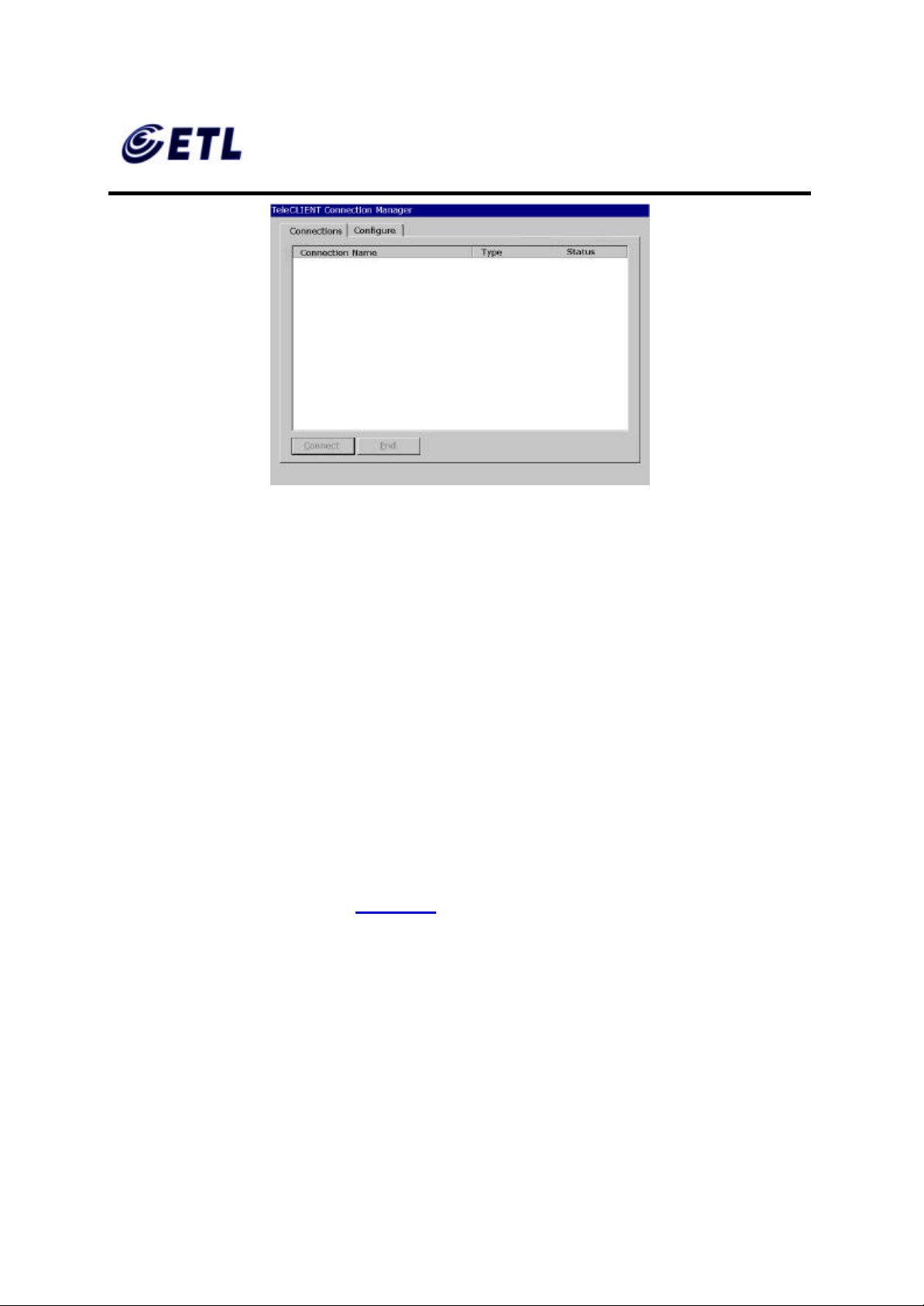
up, the TeleCLIENT Connection Manager window automatically displays (Figure 5.1)
unless it is an initial start up or ‘auto-start connection’ was set by a user. This window
will also appear whenever user logs off or disconnect from a session.
ETL Inc.
#584 Sangwhal -ri, Kanam-myon,
Yoju-kun, Kyounggi-do,
469-885, Korea 58 o 83f
17” Web Base Terminal
Model: TC7730
Page 59
FCC ID : PFMTC7730
GEMPACK CO., LTD.
Report No :E03.0718.FCC.404N
Issue of Date : July 18, 2003
Appendix F. Users Manual
Figure 5.1 TeleCLIENT Connection Manager Window
Notice that the TeleCLIENT Connection Manager window contains two tabs:
• Connections - Used to connect TeleCLIENT TC7730 to a network and also end
a network connection
• Configure - Used to add, edit and delete network connections. User can also
set the default or auto-start network connection.
5.3. Configuring Network Connections
Each connection uniquely identifies a host (server) and the client (terminal) used to
make the connection, based on the type of connection used. User can create, edit and
delete network connections in the TeleCLIENT Connection Manager window. To
begin:
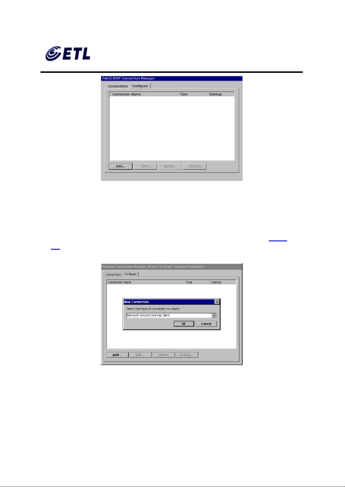
1. Select the Configure tab in the TeleCLIENT Connection Manager window. The
Configure window appears (Figure 5.2).
ETL Inc.
#584 Sangwhal -ri, Kanam-myon,
Yoju-kun, Kyounggi-do,
469-885, Korea 59 o 83f
17” Web Base Terminal
Model: TC7730
Page 60
FCC ID : PFMTC7730
GEMPACK CO., LTD.
Appendix F. Users Manual
Figure 5.2 Configure Tab Window
5.3.1. Creating a New Connection
Report No :E03.0718.FCC.404N
Issue of Date : July 18, 2003
To create a new connection, complete the following steps:
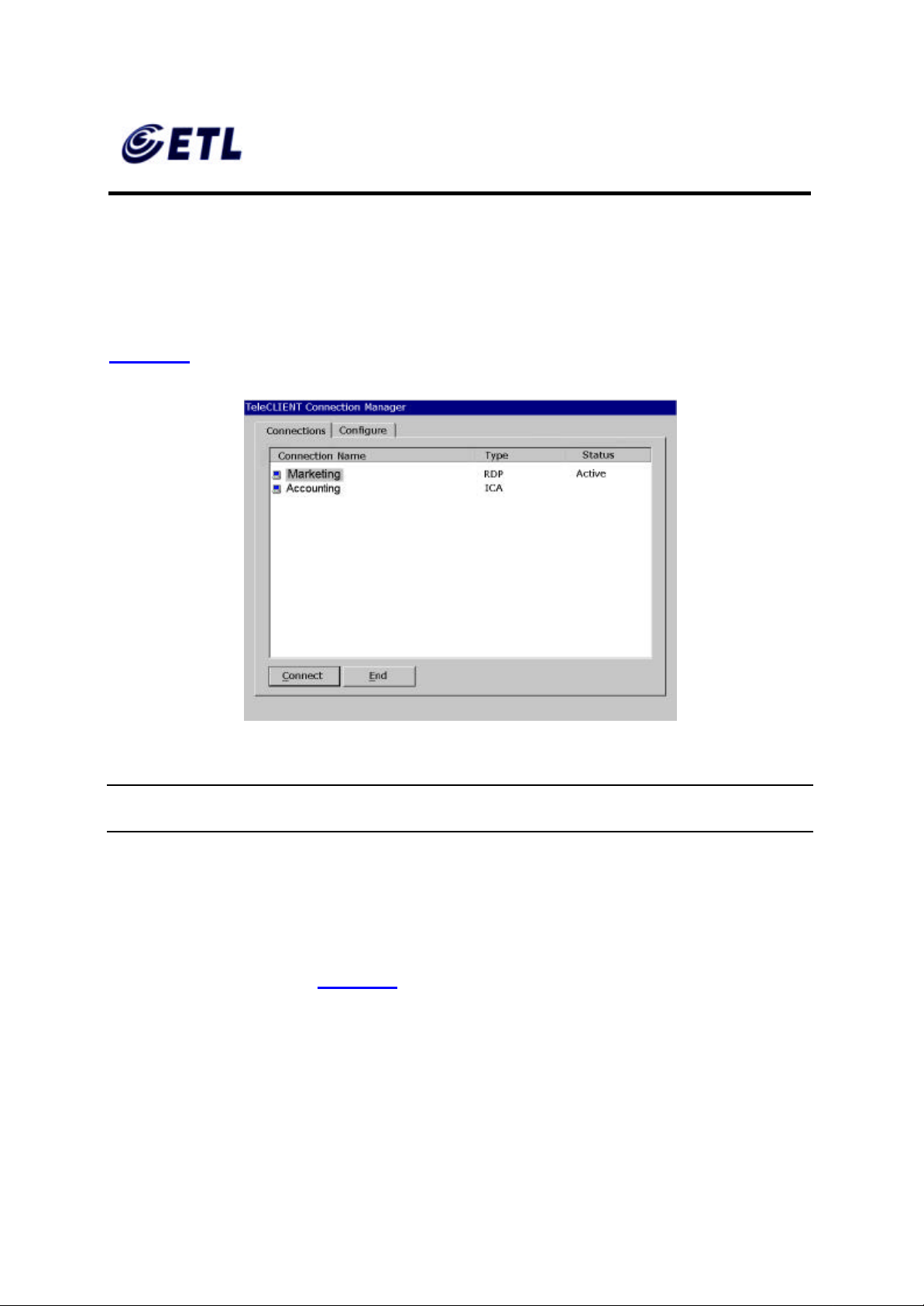
1. Click Add in the Configure window. The New Connection window appears (Figure
5.3).
Figure 5.3 New Connection Window
2. Choose one of the following connection protocols for the new connection:
• Citrix Independent Computing Architecture protocol (ICA)
ETL Inc.
#584 Sangwhal -ri, Kanam-myon,
Yoju-kun, Kyounggi-do,
469-885, Korea 60 o 83f
17” Web Base Terminal
Model: TC7730
Page 61
FCC ID : PFMTC7730
GEMPACK CO., LTD.
Report No :E03.0718.FCC.404N
Issue of Date : July 18, 2003
Appendix F. Users Manual
• Microsoft Remote Desktop Protocol (RDP)
• Terminal Emulation Client
3. To return to the previous window, click Cancel, and Click OK to proceed.
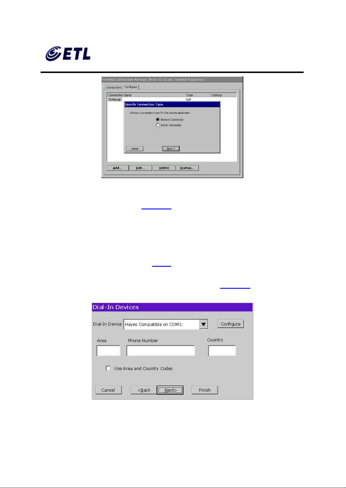
Once a connection is created, it will also be listed in the Connection Name list. In
Figure 5.4, the active connection is an RDP type.
Figure 5.4 Connection Type Defined in TeleCLIENT Connection Manager
NOTE: THE REMAINDER OF THIS PROCEDURE DEPENDS UPON THE TYPE OF
CONNECTION USED AS EXPLAINED BELOW.
♦ Adding an ICA Client Connection
To add an ICA client connection, complete the following steps:
1. Select ‘Citrix ICA Client’ in the New Connection window. The Specify Connection
Type window appears (Figure 5.3).
ETL Inc.
#584 Sangwhal -ri, Kanam-myon,
Yoju-kun, Kyounggi-do,
469-885, Korea 61 o 83f
17” Web Base Terminal
Model: TC7730
Page 62
FCC ID : PFMTC7730
GEMPACK CO., LTD.
Appendix F. Users Manual
Figure 5.5 Specify Connection Type Window
2. Specify the type of connection (Figure 5.5):
Report No :E03.0718.FCC.404N
Issue of Date : July 18, 2003
• ‘Network Connection’ - Requires an Ethernet connection.
• ‘Dial-in Connection’ - Requires a modem.
3. Click Next.
For “Network Connection’ part, skip to Step 12.
4. In Dial- In Connection box, enter the area code, phone number, country, and check
the box if it needs to dial the area code for the connection ( Figure 5.6).
Figure 5.6 Dial-In Device Setting
ETL Inc.
#584 Sangwhal -ri, Kanam-myon,
Yoju-kun, Kyounggi-do,
469-885, Korea 62 o 83f
17” Web Base Terminal
Model: TC7730
Page 63
FCC ID : PFMTC7730
GEMPACK CO., LTD.
Report No :E03.0718.FCC.404N
Issue of Date : July 18, 2003
Appendix F. Users Manual
5. Select the hardware connection from the drop -down box.
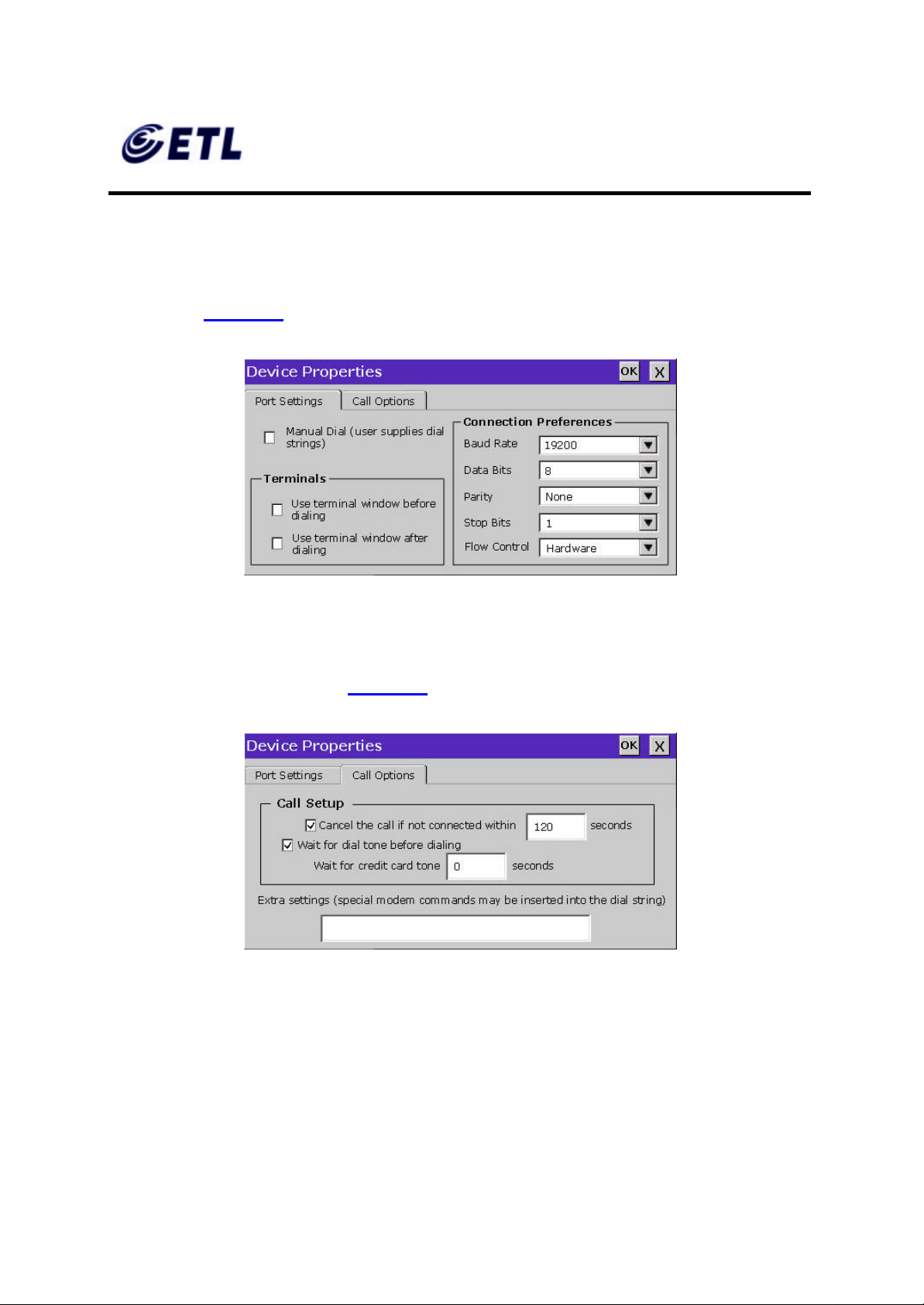
6. Click Configure .
7. Under the Port Settings tab, set Manual dialing option and the terminal screen
options (Figure 5.7).
Figure 5.7 Port Settings
8. Set the modem connection by filling in the Connection Preferences boxes.
9. Click on Call Options tab (Figure 5.8).
Figure 5.8 Calling Options
10. Set the calling options then click OK.
11. Click Next.
ETL Inc.
#584 Sangwhal -ri, Kanam-myon,
Yoju-kun, Kyounggi-do,
469-885, Korea 63 o 83f
17” Web Base Terminal
Model: TC7730
Page 64
FCC ID : PFMTC7730
GEMPACK CO., LTD.
Report No :E03.0718.FCC.404N
Issue of Date : July 18, 2003
Appendix F. Users Manual
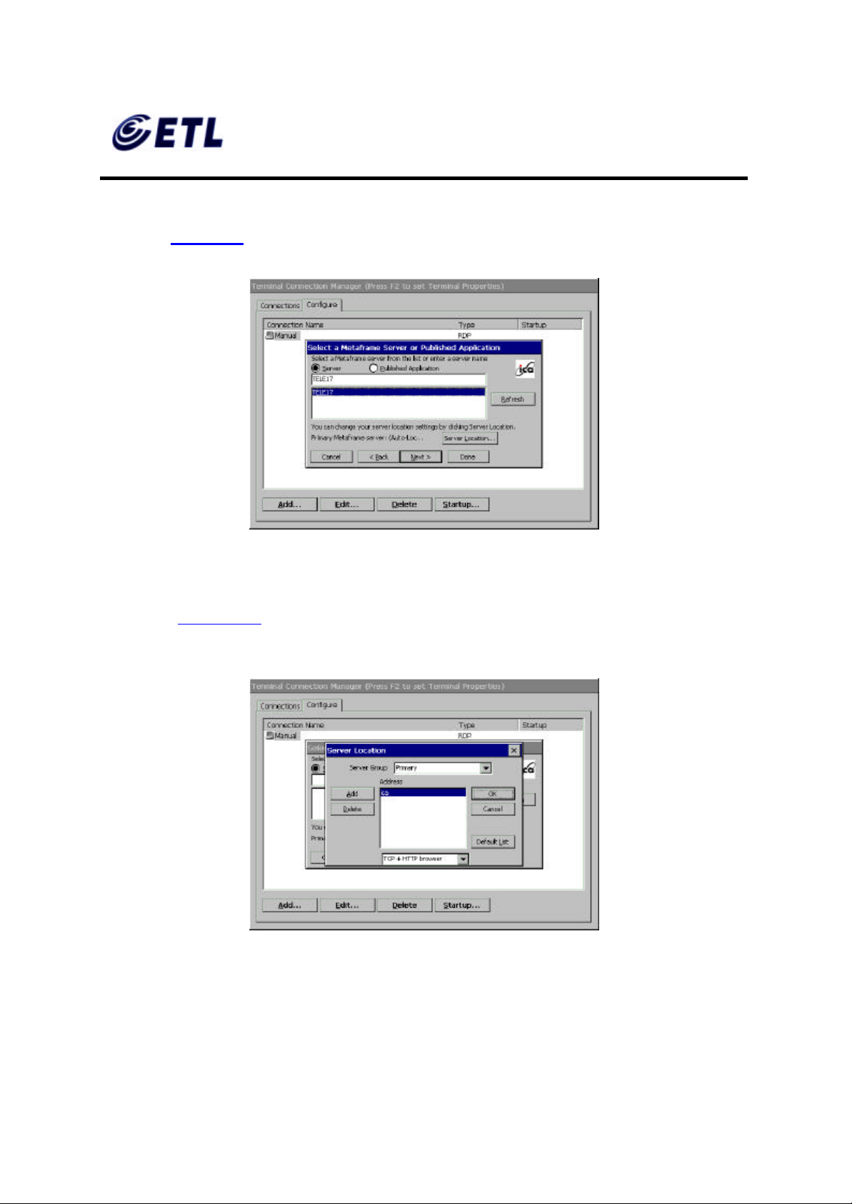
12. The software will now search for and identify all of the available Citrix servers or
published applications. Follow the prompts to select the server or application to be
used (Figure 5.9). Dial -up setup does not need this step.
Figure 5.9 Select a Citrix Server or Published Application
13. For an additional search for Servers or Application hosts, click Server Location
button ( Figure 5.10). This narrows the server search criteria. Follow the prompts to
setup the parameter.
Figure 5.10 Server Location
14. Click OK then click Refresh to start the search. If no server is listed try typing in the
IP address of the known server.
ETL Inc.
#584 Sangwhal -ri, Kanam-myon,
Yoju-kun, Kyounggi-do,
469-885, Korea 64 o 83f
17” Web Base Terminal
Model: TC7730
Page 65
FCC ID : PFMTC7730
GEMPACK CO., LTD.
Report No :E03.0718.FCC.404N
Issue of Date : July 18, 2003
Appendix F. Users Manual
15. Click Next.
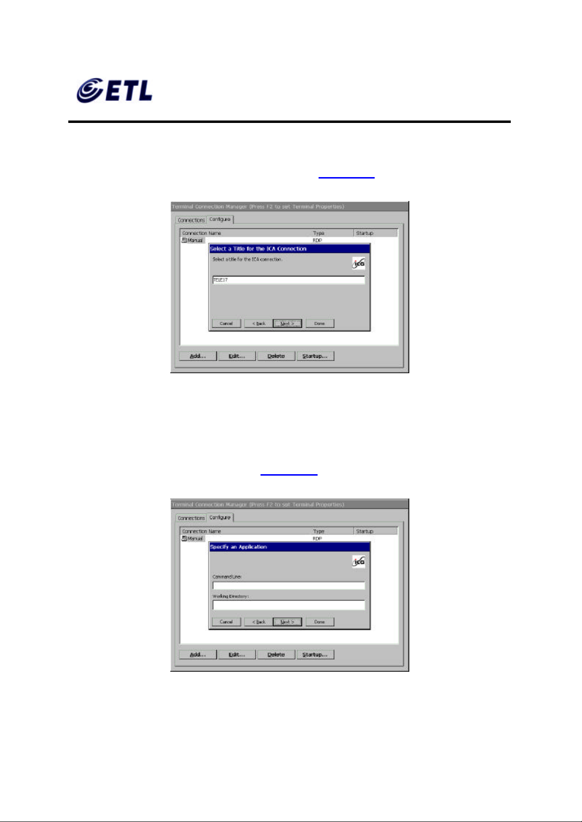
16. The default server name will appear in the Select a Title for the ICA Connection
window. This title may be ch anged at this time (Figure 5.11 ).
Figure 5.11 Select a Title for the ICA Connection Window
17. Click Next.
18. TC7730 can be configured to run the same application from the selected server.
Type in the ‘ Command Line’ and ‘Working Directory’, or leave blank to run the
Windows Terminal Server desktop (Figure 5.12).
Figure 5.12 Specify an Application Window
ETL Inc.
#584 Sangwhal -ri, Kanam-myon,
Yoju-kun, Kyounggi-do,
469-885, Korea 65 o 83f
17” Web Base Terminal
Model: TC7730
Page 66
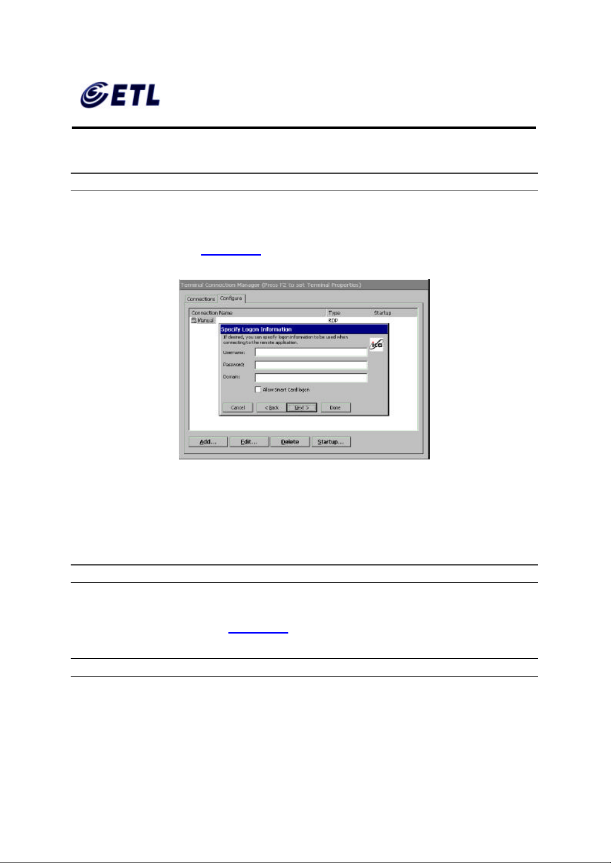
FCC ID : PFMTC7730
GEMPACK CO., LTD.
Report No :E03.0718.FCC.404N
Issue of Date : July 18, 2003
Appendix F. Users Manual
19. Click Next.
NOTE: THIS SCREEN MAYBE LEFT BLANK.
20. To utilize Specific Logon procedure, type in username, password and domain to
log on to the server. This saves users from logging on each and every time to the
server or application (Figure 5.13).
Figure 5.13 Specify Logon Information Window
21. If Smart Card logon is available on the network, check the box.
22. Click Next.
NOTE: THIS SCREEN MAYBE LEFT BLANK.
23. The Select Window Options window allows users to specify 16, 256, or Thousands
colors for the ICA session (Figure 5.14).
NOTE: 16BPP RESOLUTI ON MUST BE SELECTED AT TERMINAL PROPERTIES
ETL Inc.
#584 Sangwhal -ri, Kanam-myon,
Yoju-kun, Kyounggi-do,
469-885, Korea 66 o 83f
17” Web Base Terminal
Model: TC7730
Page 67
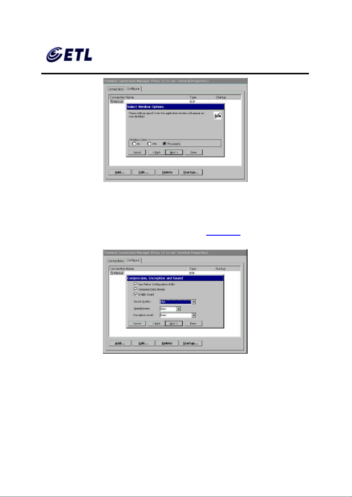
FCC ID : PFMTC7730
GEMPACK CO., LTD.
Appendix F. Users Manual
Figure 5.14 Select Window Options Window
24. Click Next.
Report No :E03.0718.FCC.404N
Issue of Date : July 18, 2003
25. The Compression, Cache and Sound window allows users to configure your ICA
session depending on the speed of the connection (Figure 5.15 ).
Figure 5.15 Compression, Cache and Sound Window
• ‘Compress Data Stream’ – Choose this setting if user is connected via a modem
dial-up or a Wide Area Network (WAN).
• ‘Cache’ – Under all ICA sessions, caching is enabled. Therefore, this setting
cannot be changed.
ETL Inc.
#584 Sangwhal -ri, Kanam-myon,
Yoju-kun, Kyounggi-do,
469-885, Korea 67 o 83f
17” Web Base Terminal
Model: TC7730
Page 68
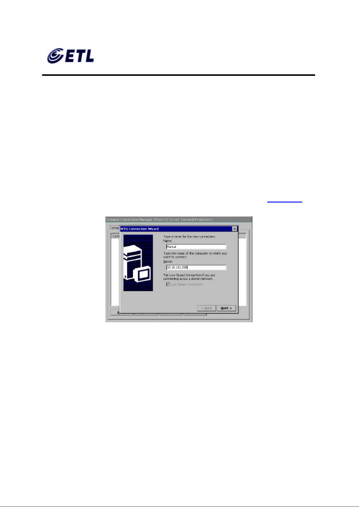
FCC ID : PFMTC7730
GEMPACK CO., LTD.
Report No :E03.0718.FCC.404N
Issue of Date : July 18, 2003
Appendix F. Users Manual
• ‘Enable Sound’ – Choose this setting if user has a Local Area Connection, i.e.
10/100BaseT. Enabling sound over a modem dial-up or a WAN will cause
problems due to an increased consumption of bandwidth.
26. Click Next (or click Finish if firewall configuration is not necessary. Skip the
following procedure; it is ready to start a terminal session!).
27. Type in the Proxy settings then click Done.
♦ Adding an RDP Client Connection
1. Select ‘Microsoft Remote Desktop Client’ in the New Connection window. The
Windows Terminal Server (WTS) Connection Wizard windo w appears (Figure 5.16 ).
2. Enter a name for the new connection in the ‘Name’ field.
3. Enter the server name or IP address of the computer you wish to connect to in the
4. If the connection to the Server is through a low bandwidth line (WAN or serial line),
5. Click Next.
Figure 5.16 WTS Connection Wizard Window
‘Server’ field.
check Low Speed Connection .
ETL Inc.
#584 Sangwhal -ri, Kanam-myon,
Yoju-kun, Kyounggi-do,
469-885, Korea 68 o 83f
17” Web Base Terminal
Model: TC7730
Page 69
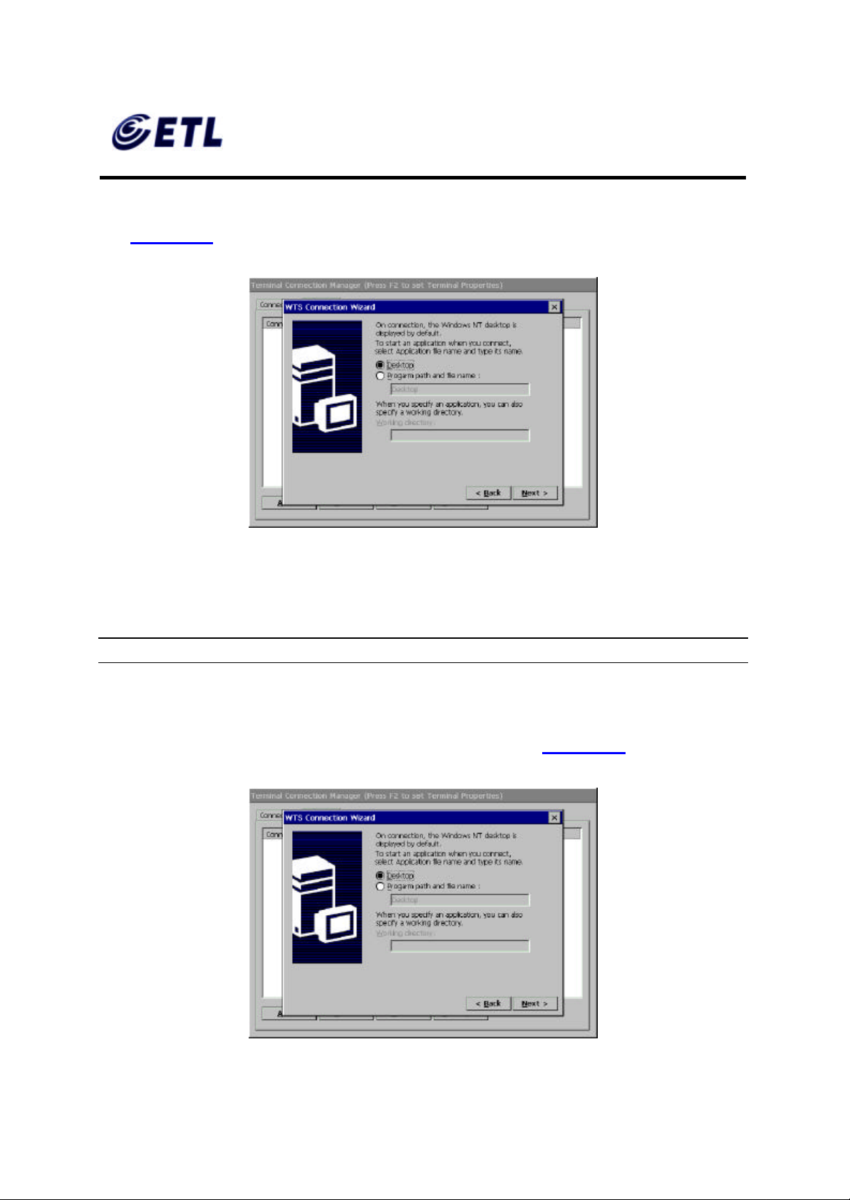
FCC ID : PFMTC7730
GEMPACK CO., LTD.
Report No :E03.0718.FCC.404N
Issue of Date : July 18, 2003
Appendix F. Users Manual
6. User’s name can enter the username, password and domain to log on to the server.
This saves users from logging on each and every time to the se rver or application
(Figure 5.17 ).
Figure 5.17 WTS Connection Wizard Window
7. Click Next.
NOTE: THIS SCREEN MAYBE LEFT BLANK.
8. User can configure TC7730 to run a selected application, instead of the desktop.
Choose the ‘Application File Name’. Type in the ‘Command Line’ and ‘Working
Directory’, or leave blank to run the Windows NT desktop ( Figure 5.18).
ETL Inc.
#584 Sangwhal -ri, Kanam-myon,
Yoju-kun, Kyounggi-do,
469-885, Korea 69 o 83f
17” Web Base Terminal
Model: TC7730
Page 70
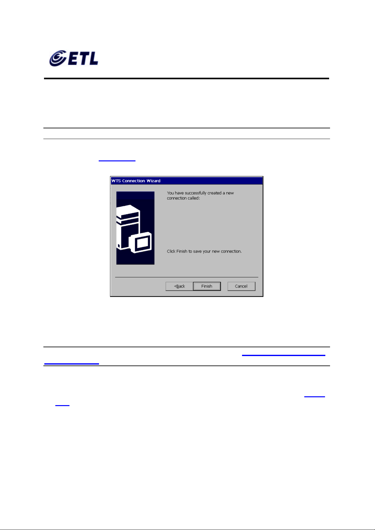
FCC ID : PFMTC7730
GEMPACK CO., LTD.
Appendix F. Users Manual
Figure 5.18 WTS Connection Wizard Window
9. Click Next.
NOTE: THIS SCREEN MAYBE LEFT BLANK.
10. Click Finish (Figure 5.19).
Report No :E03.0718.FCC.404N
Issue of Date : July 18, 2003
Figure 5.19 WTS Connection Wizard Window
♦ Adding a Terminal Emulation Client Connection
NOTE: FOR MORE INFORMATION, PLEASE REFER TO - TERMINAL EMULATION
USER’S GUIDE
1. Select ‘Terminal Emulation Clien t’ in the New Connection window. The
TeleCLIENT Terminal Emulation Connection Properties window appears (Figure
5.20).
ETL Inc.
#584 Sangwhal -ri, Kanam-myon,
Yoju-kun, Kyounggi-do,
469-885, Korea 70 o 83f
17” Web Base Terminal
Model: TC7730
Page 71
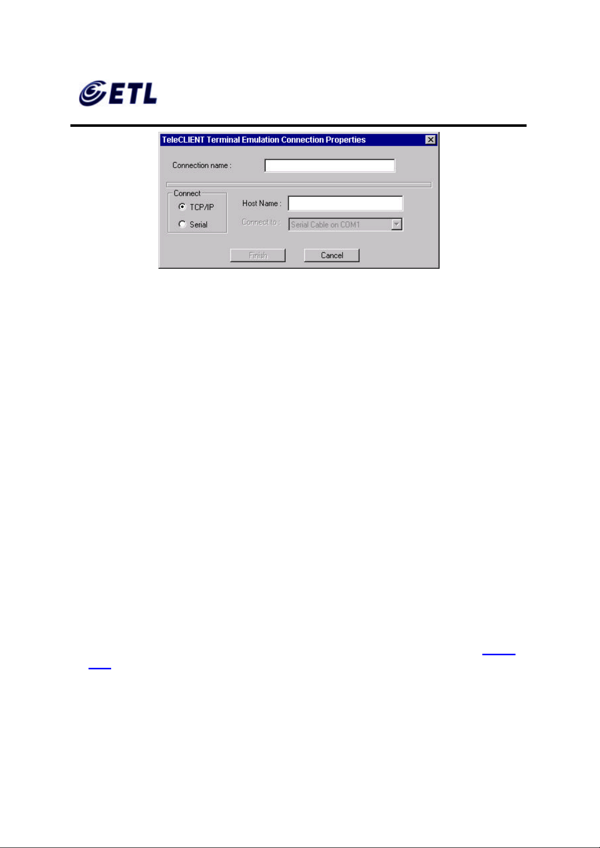
FCC ID : PFMTC7730
GEMPACK CO., LTD.
Report No :E03.0718.FCC.404N
Issue of Date : July 18, 2003
Appendix F. Users Manual
Figure 5.20 Terminal Emulation Connection Properties Window
2. Enter a name in the ‘Connection Name’ field.
3. Select the desired connection type, either TCP/IP or Serial.
• If TCP/IP is selected, enter IP address of the host computer (server) in the Host
Name field.
• If Serial is selected, choose either of COM1 or COM, whichever is being
connected.
4. Click Finish .
Once finished the TeleCLIENT Terminal Emulation setup, the terminal is now ready to
connect to the server.
5.3.2. Editing Connections
The procedure for editing a connection varies, depending on the kind of network
connection.
♦ Editing an ICA Connection
To edit an ICA connectio n, complete the following steps:
1. Select the Configure tab in the TeleCLIENT Connection Manager window (Figure
5.21).
ETL Inc.
#584 Sangwhal -ri, Kanam-myon,
Yoju-kun, Kyounggi-do,
469-885, Korea 71 o 83f
17” Web Base Terminal
Model: TC7730
Page 72
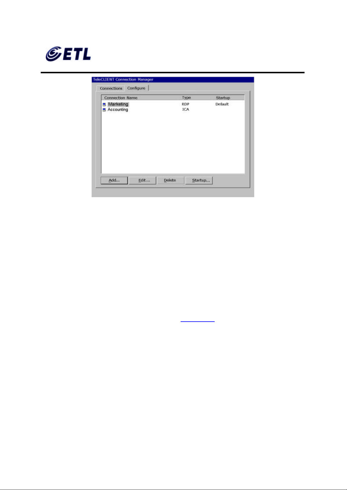
FCC ID : PFMTC7730
GEMPACK CO., LTD.
Appendix F. Users Manual
Figure 5.21 Configure Tab
Report No :E03.0718.FCC.404N
Issue of Date : July 18, 2003
2. Select the connection to be edited from the ‘ Connection Name’ list.
3. Click Edit.
4. Follow the prompts to select a Citrix Server or Published Application.
♦ Editing an RDP Connection
1. Select the Configure tab in the TeleCLIENT Connection Manager window.
2. Select the RDP connection to be edited from the ‘Connection Name’ list.
3. Click Edit. The Properties window appears (Figure 5.22).
ETL Inc.
#584 Sangwhal -ri, Kanam-myon,
Yoju-kun, Kyounggi-do,
469-885, Korea 72 o 83f
17” Web Base Terminal
Model: TC7730
Page 73
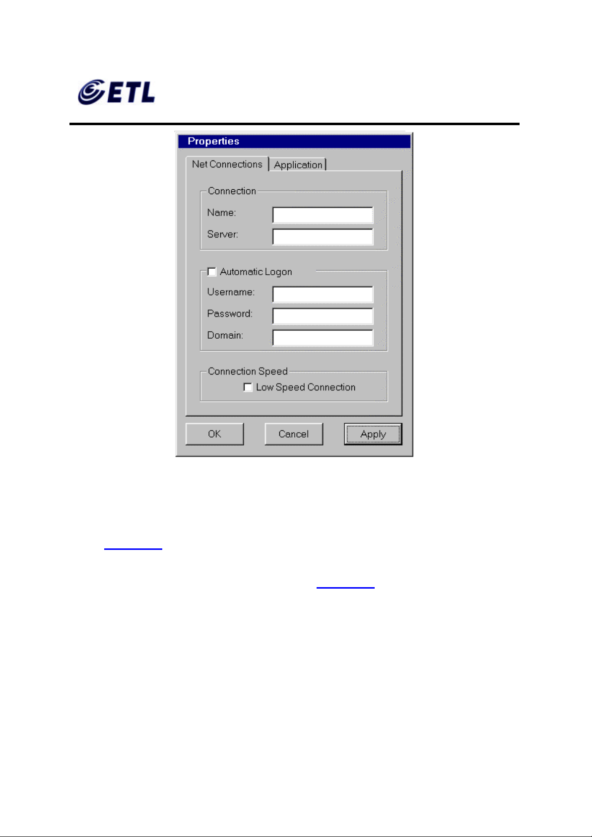
FCC ID : PFMTC7730
GEMPACK CO., LTD.
Appendix F. Users Manual
Report No :E03.0718.FCC.404N
Issue of Date : July 18, 2003
Figure 5.22 Properties Window
Notice that the Properties window contains two tabs:
• Net Connections – Used to edit a connection and enable an automatic logon
(Figure 5.22).
• Application – Used to specify and automatically go to the filename and working
directory path whenever starting a session (Figure 5.23).
ETL Inc.
#584 Sangwhal -ri, Kanam-myon,
Yoju-kun, Kyounggi-do,
469-885, Korea 73 o 83f
17” Web Base Terminal
Model: TC7730
Page 74
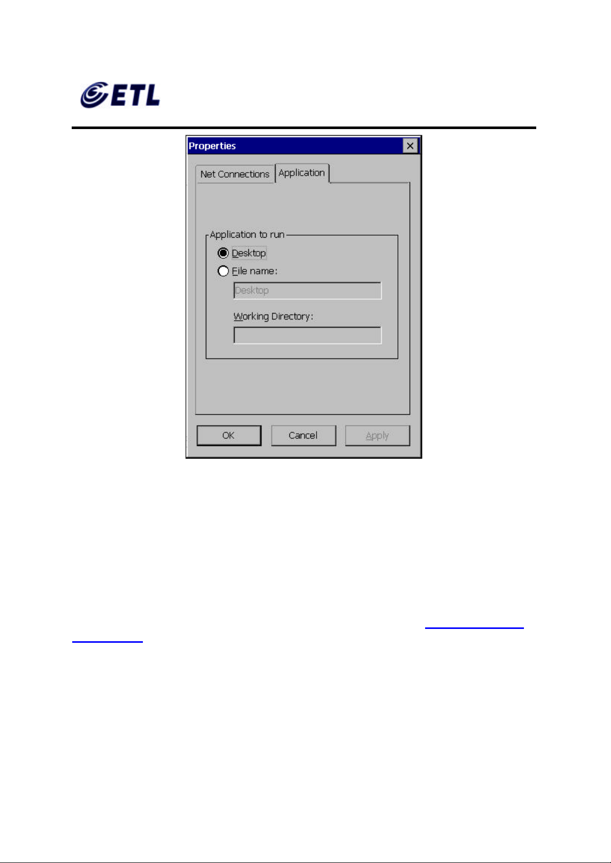
FCC ID : PFMTC7730
GEMPACK CO., LTD.
Appendix F. Users Manual
Report No :E03.0718.FCC.404N
Issue of Date : July 18, 2003
Figure 5.23 Properties Window - Application Tab
4. Make the necessary changes in the ‘Net Connections’ or ‘Application’.
5. Click Apply.
6. When finished, click OK.
♦ Editing a Terminal Emulation Connection
Please refer to Adding a Terminal Emulation Client section or the Terminal Emulation
User’s Guide.
5.3.3. Deleting a Connection
1. Select the Configure tab in the TeleCLIENT Connection Manager window.
2. Select the connection to be deleted by clicking on connection name.
ETL Inc.
#584 Sangwhal -ri, Kanam-myon,
Yoju-kun, Kyounggi-do,
469-885, Korea 74 o 83f
17” Web Base Terminal
Model: TC7730
Page 75
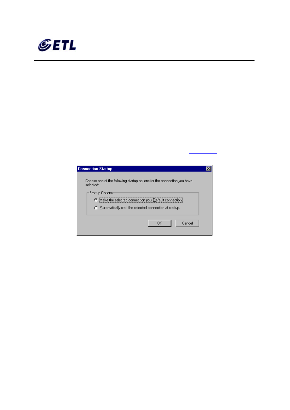
FCC ID : PFMTC7730
GEMPACK CO., LTD.
Report No :E03.0718.FCC.404N
Issue of Date : July 18, 2003
Appendix F. Users Manual
3. Click Delete .
4. Click Yes to confirm the deletion.
5.3.4. Setting Start-up Connections
The TeleCLIENT TC7730 can be set to autom atically connect to a server whenever a
session begins instead of using the default server.
To set automatic start-up connections, complete the following steps:
1. Select the Configure tab in the TeleCLIENT Connection Manager window.
2. Click Startup . The Connection Startup window appears (Figure 5.24).
Figure 5.24 Connection Startup Window
3. Select one of the following Startup Options:
• Make the selected connection the default connection – Enables the default
connection selected in the TeleCLIENT Connection Manager. The default
connection is the one highlighted when TeleCLIENT TC7730 powers on and
TeleCLIENT Connection Manager window appears.
• Automatically start the selected connection at startup – Enables the TeleCLIENT
TC7730 to automatically connect to the selected in the TeleCLIENT Connection
Manager each time a user starts up TeleCLIENT TC7730.
4. Click OK to save your changes.
ETL Inc.
#584 Sangwhal -ri, Kanam-myon,
Yoju-kun, Kyounggi-do,
469-885, Korea 75 o 83f
17” Web Base Terminal
Model: TC7730
Page 76
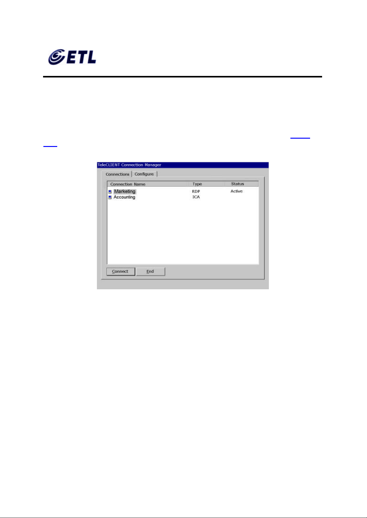
FCC ID : PFMTC7730
GEMPACK CO., LTD.
Report No :E03.0718.FCC.404N
Issue of Date : July 18, 2003
Appendix F. Users Manual
5.4. Connecting to a Network Server
The TeleCLIENT Connection Manager lists all of your system’s available network
connec tions.
To connect to a server, complete the following steps:
Click the Connections tab in the TeleCLIENT Connection Manager window (Figure
5.25).
Figure 5.25 TeleCLIENT Connection Manager Window
1. Select a Connection Name in the connection list.
2. Click Connect (or double-click on the Connection Name). If the connection was
defined for automatic logon and the server it connects to is enabled, the TeleCLIENT
TC7730 makes the connection and the user is automatically logged on.
3. If the logon is not automatic, the Windows Logon Information window displays.
Follow the Windows prompts to complete the logon.
5.5. Using the TeleCLIENT TC7730 Hot Keys
The TeleCLIENT TC7730 hot keys simplify the process of switching between active
sessions. Instead of using the TeleCLIENT Connection Manager, users can use the
hot keys on the TeleCLIENT TC7730 keyboard to automatically switch between
sessions in a single step.
ETL Inc.
#584 Sangwhal -ri, Kanam-myon,
Yoju-kun, Kyounggi-do,
469-885, Korea 76 o 83f
17” Web Base Terminal
Model: TC7730
Page 77
FCC ID : PFMTC7730
GEMPACK CO., LTD.
Report No :E03.0718.FCC.404N
Issue of Date : July 18, 2003
Appendix F. Users Manual
There are several available TeleCLIENT hot keys, described in Table 5-1.
Table 5-1 TeleCLIENT TC7730 Hot Keys
Hot Key Function
CTRL+ALT+up arrow Toggles up between active sessions.
CTRL+ALT+down arrow Toggles down between active
sessions.
CTRL+ALT+HOME Automatically toggles to the default
session.
CTRL+ALT+END Toggles directly to the TeleCLIENT
Connection Manager.
<F2> When the TeleCLIENT Connection
Manager is active, toggles directly to
the TeleCLIENT Terminal Properties
window.
If hot keys are not enabled, follow the instructions in Section 5.5.1, Starting Multiple
Connections to switch between active connections.
5.5.1. Starting Multiple Connections
The TeleCLIENT TC7730 allows multiple simultaneous connections. The number of
connections started is limited by the amount of RAM available in the TeleCLIENT
TC7730.
♦ To start a second connection, complete the f ollowing steps:
1. Press CTRL+ALT+END on the keyboard to access the TeleCLIENT Connection
Manager.
2. Select the Connection Name. Click Connect.
♦ To switch between running connections, complete the following steps:
1. Press CTRL+ALT+END on the keyboard to access the TeleCLIENT Connection
Manager.
ETL Inc.
#584 Sangwhal -ri, Kanam-myon,
Yoju-kun, Kyounggi-do,
469-885, Korea 77 o 83f
17” Web Base Terminal
Model: TC7730
Page 78

FCC ID : PFMTC7730
GEMPACK CO., LTD.
Report No :E03.0718.FCC.404N
Issue of Date : July 18, 2003
Appendix F. Users Manual
2. Select a Connection Name. Click Connect.
3. OR, on the keyboard, press CTRL+ALT+UP (with the up arrow) or
CTRL+ALT+DOWN (with the down arrow) to cycle through the list of active
connections. The Connection list reflects the order in which the connections were
started, with the most recent at the top of the list.
5.6. Logging Off
To log off and end a session:
When connected to an application, close the application to terminate the connection.
When connected to a server’s desktop, complete the following steps:
1. Close all applications.
2. Click Start on the taskbar at the bottom of the Windows Terminal Server (WTS)
desktop.
3. Select Logoff .
4. Click OK in the panel that displays. WTS closes any programs that are still running.
A new session will now start, or the TeleCLIENT Connection Manager window will
appear. The TeleCLIENT TC7730 may now be powered off.
5.6.1. Ending Auto-Start Connections
To end an auto-start connection, complete the following steps:
1. Press CTRL+ALT+END on the keyboard to access the TeleCLIENT Connection
Manager.
2. Select the Configure tab.
3. Select the auto-start Connection Name and click Startup. The TeleCLIENT
Connection Startup window appears.
4. Click on the ‘Make the selected’ connection your Default connection. Click OK.
5. Select the connection and click End.
ETL Inc.
#584 Sangwhal -ri, Kanam-myon,
Yoju-kun, Kyounggi-do,
469-885, Korea 78 o 83f
17” Web Base Terminal
Model: TC7730
Page 79

FCC ID : PFMTC7730
GEMPACK CO., LTD.
Report No :E03.0718.FCC.404N
Issue of Date : July 18, 2003
Appendix F. Users Manual
6. Appendix A
6.1. Specifications
This chapter contains the following TeleCLIENT TC7730 specifications:
• Hardware Specifications
• Networking and Communications
• Software Specifications
• Environmental
• Regulatory Compliance
• Physical Characteristics
• Warranty Information
6.1.1. TeleCLIENT TC7730 Hardware Specifications
Hardware Description
CPU
RAM Memory
Flash Memory
Graphics Subsystem
Audio Support
§ VIA Eden ESP 5000 533MHz
§ 64MB RAM standard
§ Expandable to 256MB
§ 32MB DOM or 32MB CompactFlash up to
256MB
§ Flash upgrade utility via Ethernet
§ VIA VT8606 North Bridge
§ Resolution of 1200x1024
§ 32-bit (24) True colors
§ Supports all VESA monitors
§ VIA VT8231 controlled, with VT1611A
AC’97 Audio Codec
§ Full 16 -bit stereo FM synthesis
§ Built- in speaker system
§ Audio Out –Microphone in
TeleCLIENT TC7730 Hardware Specifications
ETL Inc.
#584 Sangwhal -ri, Kanam-myon,
Yoju-kun, Kyounggi-do,
469-885, Korea 79 o 83f
17” Web Base Terminal
Model: TC7730
Page 80
FCC ID : PFMTC7730
GEMPACK CO., LTD.
TeleCLIENT Setup Wizard for
Report No :E03.0718.FCC.404N
Issue of Date : July 18, 2003
Appendix F. Users Manual
6.1.2. Networking, Communications And Input/Output
Specifications
Item Description
Networking Protocols
Communication Protocols
Parallel Port
Serial Port
USB Ports
Audio Ports
Keyboard and Mouse Ports
Networking, Communications and Input/Output Specifications
§ 10/100BaseT Ethernet, RJ45,
IEEE 802.11B Wireless LAN
§ TCP/IP with DNS, DHCP and
PPP
§ Load balancing supported by
Citrix ICA
§ Remote modem dial up with
Citrix ICA
§ Microsoft RDP
§ Citrix ICA
§ One parallel port
§ One serial port
§ Two USB ports
§ Audio out
§ Microphone in
§ Keyboard and mouse ports
(PS/2 keyboard and mouse
included)
6.1.3. TeleCLIENT TC7730 Software Specifications
Feature Description
Operating System
Set-up and Configu ration
§ Microsoft Windows CE
§
fast, simple connection to the
network
§ Login configured for server
access
§ Familiar Windows graphical user
ETL Inc.
#584 Sangwhal -ri, Kanam-myon,
Yoju-kun, Kyounggi-do,
469-885, Korea 80 o 83f
17” Web Base Terminal
Model: TC7730
Page 81

FCC ID : PFMTC7730
GEMPACK CO., LTD.
Appendix F. Users Manual
Remote Management Software
Server Operating System Support*
Terminal Emulation Support*
Report No :E03.0718.FCC.404N
Issue of Date : July 18, 2003
interface
§ Local power- on
§ TeleManager Management
Software
§ Microsoft Windows NT Server
4.0, Terminal Server Edition
§ Microsoft Windows 2000
Terminal Services
§ Windows XP Professional
§ Windows Server 2003
§ Citrix WinFrame
§ Citrix MetaFrame
§ TeleManager Remote
Management Software compatible
§ TVI 925, 950, 955
§ VT100..VT520. Ansi BBS. SCO
Console. AixTerm,
§ Wyse 50, 50+, 60,
§ Hazeltine 1500, ADDS A2
§ IBM 3270: TN3270E, TN3287 Printing
§ IBM5250: TN5250, TN3812 Printing
§ IBM 3151
§ HP Suite: HP 2392A, 2622A, 700/92
Software Specifications
* Term inal emulation support optional. Additional emulations available by request only.
Please contact TeleVideo directly for further information.
6.1.4. Environmental Specifications
Feature Description
Environmental Specifications
ETL Inc.
#584 Sangwhal -ri, Kanam-myon,
Yoju-kun, Kyounggi-do,
469-885, Korea 81 o 83f
17” Web Base Terminal
Model: TC7730
§ Operating temperature 30º to
104ºF (0º to 40ºC)
§ Storage temperature -4º to
140ºF (-20º to 60ºC)
§ State-of-the art, fanless
convection cooling design
§ Humidity 20% to 85%, non condensing
§ Operating altitude of 0 to 10,000
feet (3050 meters)
Page 82
FCC ID : PFMTC7730
GEMPACK CO., LTD.
Appendix F. Users Manual
Report No :E03.0718.FCC.404N
Issue of Date : July 18, 2003
Power Supply Specifications
§ External power suppl y
§ 100-240 VAC at 50-60Hz
§
4.58A
§ 55W nominal
Environmental Specifications
6.1.5. Regulatory Compliance Specifications
Feature
Regulations
Regulatory Compliance Specifications
Description
§ EPA ENERGY STAR®
§
FCC Class B
§ CE Mark
6.1.6. Physical Specifications
Feature Description
Weight
Height
Depth
Width
Physical Specifications
§ 7.3kg
§ 430 mm
§ 270 mm
§ 393 mm
6.1.7. Warranty Information
The TeleCLIENT TC7730 is supported by a one-year warranty service. Please contact
your TeleVideo, Inc. representative for more information.
ETL Inc.
#584 Sangwhal -ri, Kanam-myon,
Yoju-kun, Kyounggi-do,
469-885, Korea 82 o 83f
17” Web Base Terminal
Model: TC7730
Page 83

FCC ID : PFMTC7730
GEMPACK CO., LTD.
Report No :E03.0718.FCC.404N
Issue of Date : July 18, 2003
Appendix F. Users Manual
FCC Information
FCC Part 15.105
Note: This equipment has been tested and found to comply with the limits for a Class B digital device,
pursuant to part 15 of the FCC Rules.
These limits are designed to provide reasonable protection against harmful interference in a residential
Installation. This equipment generates, uses, and can radiate radio frequency energy and, if not installed
and used in accordance with the instructions. May cause harmful interference to radio communications.
However, there is no guarantee that interference will not occur in a particular installation. If this equipment
does cause harmful interference to radio or television reception, which can be determined by turning the
equipment off and on, the user is encouraged to try to correct the interference by one or more of the
following measures:
- Reorient or relocate the receiving antenna.
- Increase the separation between the equipment and receiver.
- Connect the equipment into an outlet on a circuit different from that to which the
receiver is connected
- Consult the dealer or an experience radio / TV technician for help
FCC Part 15.21
Changes or modifications not expressly approved by the party responsible for compliance Could void the
user`s authority to operate the equipment
ETL Inc.
#584 Sangwhal -ri, Kanam-myon,
Yoju-kun, Kyounggi-do,
469-885, Korea 83 o 83f
17” Web Base Terminal
Model: TC7730
 Loading...