

Page 1

ATTACHMENT E.
- USER’S MANUAL
-- 11 / 69 / 69 –
Page 2
-- 22 / 69 / 69 –
Page 3

TeleCLIENT TC7370
Preface...............................................................................................................................1
Introduction ........................................................................................................................5
1. Introduction ............................................................................................................5
1.1. Safety Instructions ........................................................................................5
1.1.1. Safety Notices.......................................................................................5
1.1.2. Other Product Safety Considerations................................................5
1.2. Introduction ....................................................................................................6
1.2.1. Features .................................................................................................6
1.3. Equipment Overview....................................................................................7
Hardware............................................................................................................................8
2. Hardware Installation............................................................................................8
2.1. Rear Panel.....................................................................................................8
2.1.1. I/O Ports .................................................................................................8
2.1.2. Connecting the TeleCLIENT TC7370 ................................................9
2.2. Powering on the TeleCLIENT TC7370...................................................10
2.3. Front Control Panel...................................................................................10
2.3.1. Activity LED.........................................................................................10
2.3.2. Ethernet LED......................................................................................11
2.4. Troubleshooting .........................................................................................11
2.5. PowerSaver ................................................................................................11
Software ..........................................................................................................................12
3. Software Configuration.....................................................................................12
3.1. Using the TeleCLIENT Setup Wizard.....................................................12
3.2. Setting TeleCLIENT TC7370 Properties ................................................ 18
3.2.1. Resetting the TeleCLIENT TC7370 to Factory Defaults .............19
3.2.2. Setting Keyboard Characteristics....................................................19
3.2.3. Setting Display Characteristics........................................................20
3.2.4. Changing Network Settings..............................................................21
3.2.5. Printer Settings...................................................................................22
3.2.6. Changing System Settings...............................................................23
3.2.7. Viewing Management Settings........................................................26
3.2.8. Viewing the Network Information.....................................................28
3.3. TeleCLIENT™ Software Update .............................................................29
3.3.1. Overview.............................................................................................29
3.3.2. TeleCLIENT Setup Property Page..................................................30
3.3.3. Verifying Package File Contents.....................................................32
Operation.........................................................................................................................33
4. Operation.............................................................................................................33
4.1. Powering On ............................................................................................... 33
-- 33 / 69 / 69 –
Page 4

4.2. Using the TeleCLIENT Connection Manager........................................33
4.3. Configuring Network Connections...........................................................34
4.3.1. Creating a New Connection.............................................................34
4.3.2. Editing Connections...........................................................................42
4.3.3. Deleting a Connection .......................................................................44
4.3.4. Setting Start-up Connections...........................................................44
4.4. Connecting to a Network Server .............................................................44
4.5. Using the TeleCLIENT TC7370 Hot Keys .............................................45
4.5.1. Starting Multiple Connections ..........................................................46
4.6. Logging Off.................................................................................................46
4.6.1. Ending Auto-Start Connections .......................................................46
Appendix A......................................................................................................................48
5. Specifications .....................................................................................................48
Preface
Purpose
The purpose of this manual is to provide installation and operation information for the TeleCLIENT™
Windows®-Based Terminal.
Audience
This manual is intended for both authorized system administrators and users who have experience
with networking products and Windows-based terminals. It is assumed that the personnel using this
document have the appropriate background and knowledge to use the TeleCLIENT.
How To Use This Manual
This manual is designed to help you locate information quickly and easily. Each chapter contains
the following information:
Preface
Provides equipment compliance, warranty and license agreement information.
Chapter 1 Introduction
Describes the TeleCLIENT and provides basic safety information.
Chapter 2 Hardware Installation
Describes how to install the TeleCLIENT hardware.
Chapter 3 Software Configuration
Describes how to configure the TeleCLIENT software.
Chapter 4 Operation
-- 44 / 69 / 69 –
Page 5

Provides instructions for using the TeleCLIENT Terminal Connection Manager and hot keys.
Appendix
System specifications and warranty information.
Warning: The procedures described in this document are intended for authorized users only.
Unauthorized personnel performing these procedures can affect the product's warranty status.
European Telecom Statement
The TeleCLIENT is intended for connection to a Network Centric System. DO NOT connect the
TeleCLIENT to the Telecom System.
ENERGY STAR®
As an ENERGY STAR Partner, TeleVideo, Inc. has determined that this product meets the ENERGY
STAR guidelines for energy efficiency. ENERGY STAR is a U.S. registered mark.
TeleVideo, Inc. Software License Agreement
PLEASE CAREFULLY READ THE FOLLOWING TERMS AND CONDITIONS BEFORE USING THIS
SOFTWARE. USING THIS SOFTWARE INDICATES YOUR ACCEPTANCE OF THE FOLLOWING
TERMS AND CONDITIONS.
Grant
You may use the TeleCLIENT Connection Manager in conjunction with the TeleCLIENT as provided.
You may transfer ownership of the Equipment, including the right to transfer the Software to another
party so long as that party agrees to accept these terms and conditions.
YOU MAY NOT COPY, MO DIFY, TRANSLATE OR TRANSFER THE SOFTWARE, OR
MODIFICATION THEREOF, IN WHOLE OR IN PART, EXCEPT AS EXPRESSLY PROVIDED FOR
IN THIS LICENSE. YOU MAY NOT DECOMPILE, REVERSE ENGINEER, OR OTHERWISE
DECODE OR ALTER THE SOFTWARE PROVIDED WITH THIS EQUIPMENT.
Limit of Liability
UNDER NO CIRCUMSTANCES SHALL TELEVIDEO, INC. BE LIABLE FOR LOSS OF DATA,
COSTS, OR ANY INCIDENTAL OR CONSEQUENTIAL DAMAGES, HOWEVER CAUSED AND ON
ANY THEORY OF LIABILITY. THESE LIMITATIONS SHALL APPLY EVEN IF TELEVIDEO, INC. OR
ITS RESELLER HAS BEEN ADVISED OF THE POSSIBILITY OF SUCH DAMAGES, AND
NOTWITHSTANDING ANY FAILURE OF ESSENTIAL PURPOSE OF ANY LIMITED REMEDY
PROVIDED HEREIN.
WHEN USING THIS PRODUCT, YOU AGREE THAT THESE ARE THE ONLY APPLICABLE
TERMS OF AGREEMENT BETWEEN US COVERING THE SOFTWARE.
-- 55 / 69 / 69 –
Page 6

U.S. Government Restricted Rights
ation Technology Equipment (Computer
This software is provided with RESTRICTED RIGHTS. Use, duplication or disclosure by the
Government is subject to restrictions as set forth in subparagraph (c)(1)(ii) of the Rights in
Technological Data and computer software clause at DFARS 252.227-7013 or in subparagraphs
(c)(1) and (2) of the Commercial Computer Software-Restricted Rights at 8 C.F.R. 52-227-19 as
applicable. Contractor/Licensor is TeleVideo, Inc.
Declaration of Conformity
Application of CounciApplication of Council Directive:l Directive: 89/33 6/EEC, 73/23/EEC
Standard to which Conformity is Declared:Standard to which Conformity is Declared: EN55022, EN60950
Manufacturer's Name:Manufacturer's Name: TeleVideo, IncTeleVideo, Inc
Manufacturer's Address:Manufacturer's Address: 2345 Harris Way
San Jose, CA 95131 USA
408.954.8333
www.televideo.com
Type of Equipment:Type of Equipment: Inform
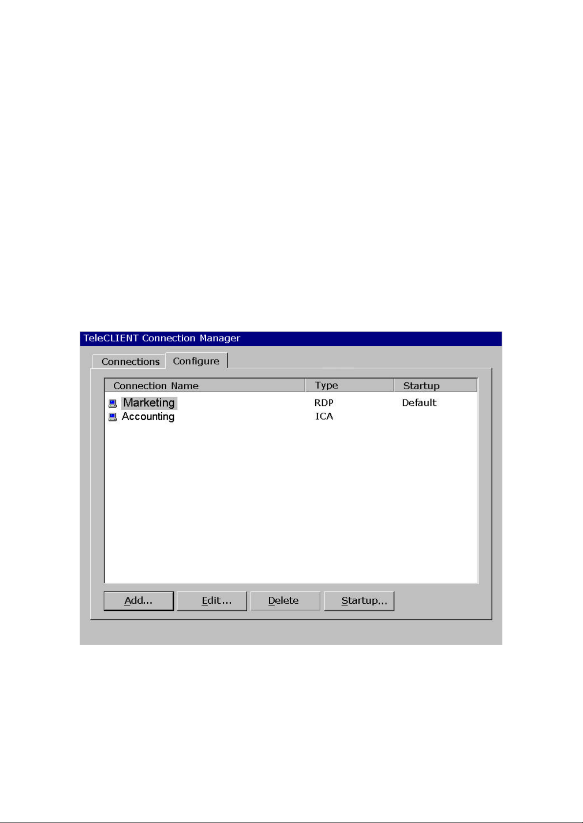
Terminal)
Statement of Limited Warranty
Scope of Limited Warranty
TeleVideo, Inc. (TeleVideo) warrants to Buyer that its products, except software, will be free from
defects in materials and workmanship for 365 days from the date of purchase. TeleVideo's
obligation under this warranty will be limited to repairing or replacing, at TeleVideo's option, the parts
of the products which prove defective in material or workmanship, provided that Buyer gives
TeleVideo prompt notice of any defect and satisfactory proof thereof.
Exclusions
This limited warranty does not cover losses or damages which occur in shipment to or from Buyer,
nor due to (1) improper installation or maintenance, misuse, neglect or any cause other than ordinary
commercial or industrial application, or (2) adjustment, repair, or modification by anyone other than
TeleVideo's authorized agent, or (3) improper environment, excessive or inadequate heating or air conditioning and electrical power failures, surges, or other irregularities, or (4) any statements made
about TeleVideo's products by sales representatives, dealers, distributors or agents, unless
confirmed in writing by a TeleVideo officer. Equipment purchased must be in a new, sealed
condition upon delivery to the end user in order to qualify for TeleVideo’s limited warranty.
The foregoing TeleVideo limited warranty is in lieu of all other warranties, whether oral, written,
expressed, implied, or statutory. Implied warranties of merchantability and fitness for a particular
purpose will not apply.
TeleVideo’s warranty obligations and Buyer's remedies hereunder are solely and exclusively as stated herein. TeleVideo makes no warranty
-- 66 / 69 / 69 –
Page 7

whatsoever concerning any software products, which are sold "as is" and "with all faults". TeleVideo's liability, whether based on contract,
tort, warranty, strict liability, or any other theory, shall not exceed the price of the individual unit whose defect or damage is the basis of
the claim. In no event shall TeleVideo be liable for any loss of profits, loss or use of facilities or equipment, or other indirect, incidental or
consequential damages.
Introduction
1. 1. Introduction
This chapter provides an overview of the TeleCLIENT Windows-Based Terminal . It includes the
following sections:
1. • Safety Instructions
2. • Introduction
3. • Equipment Overview
2. 1.1. Safety Instructions
Please read this important safety information BEFORE using your TeleCLIENT and save for later use.
3. 1.1.1. Safety Notices
Danger Notices
A danger notice indicates a hazard that could possibly cause death or serious personal injury.
Please note the following danger notices before using this product.
DANGER: This product uses electrical power and contains sensitive components. It is not designed
for consumer servicing. If your TeleCLIENT requires repair, or you wish to add components that
require opening the case, please contact your nearest service provider for assistance. Do not
attempt to service the TeleCLIENT yourself. Refer all servicing to qualified service personnel.
Unauthorized individuals who attempt to repair this product, or to install or replace components may
risk electrical shock and cause the product warranty to be void.
DANGER: To avoid a shock hazard:
4. • Connect the power cord to a properly wired and grounded power outlet.
5. • Make sure that any equipment attached to this product is also properly connected to
wired receptacles.
-- 77 / 69 / 69 –
Page 8

DANGER: The TeleCLIENT power switch is not the main disconnect. The main power disconnect is
the detachable line cord.
Warning Notices
A warning notice indicates the possibility of damage to a program, device, system or data.
4. 1.1.2. Other Product Safety Considerations
Please note the following:
1. 1. Do not expose the power supply, TeleCLIENT, line cord or monitor to
moisture, dust or corrosive gases.
2. 2. Position the TeleCLIENT in a well-ventilated area; do not allow debris
near the ventilation holes.
3. 3. Keep the TeleCLIENT away from heat sources, including direct sunshine
and heating appliances. The maximum operating temperature is 35ºC (95ºF).
4. 4. Always unplug the TeleCLIENT before cleaning. Do not use liquid
cleaners or aerosol cleaners. Use only a damp cloth for cleaning.
5. 5. Make sure the TeleCLIENT is placed on a stable surface.
6. 6. Do not block slots and openings anywhere on the TeleCLIENT.
7. 7. Use only the type of power indicated on the marking label to operate
this product. Consult your dealer or local power company if you are unsure of
the type of power available.
8. 8. Use only the proper type of power supply cord set (provided in your
accessory box) for this unit. Use a detachable type: UL listed/CSA certified,
type SVT/SJT, rated as 10A 125V minimum, VDE approved or its equivalent.
9. 9. Do not allow anything to rest on the power cord.
10. 10. If an extension cord is used with the TeleCLIENT make sure that the total
ampere ratings of all products plugged into the cord does not exceed the
extension cord ampere ratin g.
11. 11. Do not insert objects of any kind through the TeleCLIENT slots.
12. 12. Unplug this product from the wall outlet immediately and contact qualified
service personnel under the following conditions:
6. • When the power cord or plug is damaged or frayed.
7. • If liquid has been spilled into the TeleCLIENT or it has been exposed to rain or water.
8. • If the TeleCLIENT has been dropped or damaged.
13. 13. Install the socket -outlet near the equipment and make sure it is easily
accessible.
5. 1.2. Introduction
Thank you for choosing the TeleCLIENT Windows-Based Terminal. The TeleCLIENT is a “Powered
-- 88 / 69 / 69 –
Page 9

by Microsoft Windows CE” Windows®-based terminal that empowers users to access and manage
business-critical applications such as:
9. • Point-of-sale
10. • Help and reservation desk
11. • Electronic Commerce
12. • Word-processing
13. • Spreadsheets
All can be accessed through host Windows, or Unix servers and all within the familiar Windows
environment.
The TeleCLIENT provides the freedom to choose any of the following:
14. • Microsoft’s Remote Desktop Protocol (RDP®) protocol to communicate directly to a
server loaded with Microsoft Windows NT Server® 4.0, Terminal Server Edition or
Windows 2000 Terminal Services.
15. • Citrix’s Independent Computing Architecture (ICA®) protocol to communicate directly
to a server loaded with Citrix WinFrame® or Citrix MetaFrame™.
16. • Direct connection to a legacy server to run terminal emulation, such as TeleVideo
910 or 915.
Each TeleCLIENT can be configured for communication directly via TCP/IP (Transmission Control
Protocol/Internet Protocol) or PPP (Point-to-Point Protocol).
6. 1.2.1. Features
The TeleCLIENT offers the following features:
17. • Ease of Installation and Administration
The Microsoft Windows CE Operating System is embedded on a 8MB local flash disk.
The software can be upgraded and re-programmed locally or remotely via Ethernet
download.
18. • More Secure than PCs
Since there is no local storage system, administrators may keep all confidential and
business-critical files and data on the server to preserve data security and integrity.
19. • Multiple Protocols Support
System administrators may choose the Remote Desktop Protocol (RDP) that executes
on Mi crosoft Windows NT Server 4.0, Terminal Server Edition, Windows 2000 Terminal
Services, or the Independent Computing Architecture (ICA) protocol through Citrix
MetaFrame or WinFrame server systems to best fit their needs.
20. • Touch Screen Support
TeleCLIENT supports the MicroTouch and Elo Touch Screens to provide POS and kiosks
solutions.
-- 99 / 69 / 69 –
Page 10

7. 1.3. Equipment Overview
Your TeleCLIENT comes with everything needed to access your network server running under
Microsoft Windows NT Server 4.0, Terminal Server Edition, Windows 2000 Terminal Services, Citrix
WinFrame or MetaFrame or other legacy server operating systems.
You will find the following items in your package:
21. • Integrated LCD TeleCLIENT Windows-Based Terminal
22. • Keyboard: Windows compatible
23. • Two-button mouse: Standard
24. • Inline power supply: Universal power supply standard
25. • Power Line cord
26. • CD-ROM version of TeleCLIENT User’s Manual
Hardware
8. 2. Hardware Installation
This chapter explains how to install, connect and set -up the TeleCLIENT TC7370 hardware. It
includes the following sections:
27. • Connecting to I/O Ports
28. • Powering on the TeleCLIENT TC7370
29. • Front Panel Controls
30. • Troubleshooting
31. • PowerSaver
9. 2.1. Rear Panel
10.2.1.1. I/O Ports
The I/O ports for the TC7370 are located at the bottom of the unit while putting the LCD panel face
down (Figure 2-1). These include:
-- 1010 / 69 / 69 –
Page 11
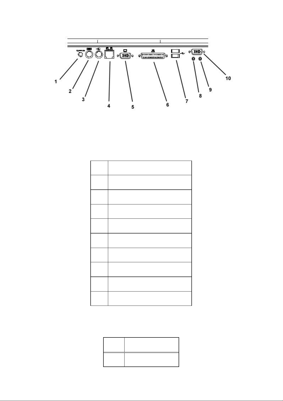
Figure 4-1 Figure 2-1 I/O Ports
1 DC-in
2 PS/2 Keyboard
3 PS/2 Mouse
4 Ethernet LAN
5 External VGA/SVGA
6 Printer/Parallel Port
7 USB Ports
Peripheral Port Pinouts
8 Earphone
9 Microphone
10 Serial Port
Pin Function
1 STROBE
-- 1111 / 69 / 69 –
Page 12

Pin Function
1 STROBE
2 D0
3 DI
4 D2
5 D3
6 D4
7 D5
8 D6
9 D7
10 ACK
11 BUSY
12 PE
13 SLCT
14 AUTOFD
15 ERR
16 INIT
17 SLCT IN
18-25 GND
11. 2.1.2. Connecting the TeleCLIENT TC7370
1. 1. Remove the TeleCLIENT TC7370, line cord, and accessories from the carton, and set the
unit on a flat work-surface.
14. 2. Connect the keyboard to the keyboard connector.
15. 3. Connect the mouse to the mouse connector.
16. 4. Depending on your configuration needs, connect a printer to the parallel
port.
-- 1212 / 69 / 69 –
Page 13

17. 5. Depending on your hardware, connect to the host:
32. • If using a network connection, connect a 10/100Base-T, twisted-pair, Category 5
RJ45 cable to the network port.
Note: The TC7370 supports both 10 Mbps and 100 Mbps LAN access. To ensure proper 100
Mbps operation the Ethernet LAN cables must be of Category 5 type.
18. 6. Plug the AC cord into an AC outlet.
CAUTION: Do not force the connectors into the sockets. If there is undue resistance, make sure the
connector is placed correctly in the socket.
2. 2.2. Powering on the TeleCLIENT TC7370
When connecting the TeleCLIENT TC7370 to AC outlets, please note the following:
3. 1. To turn on your TC7370, simply press the power button on the front panel. This will
power on both the TeleCLIENT TC7370 terminal and the monitor. If the monitor displays an
image, installation is complete.
WARNING! To prevent risk of fire or electric shock, please follow these instructions carefully.
4. 2.3. Front Control Panel
The front bezel of the TC7370 has three LED lights and other control but tons. The power button is
designed to turn on or off system under light pressure.
-- 1313 / 69 / 69 –
Page 14
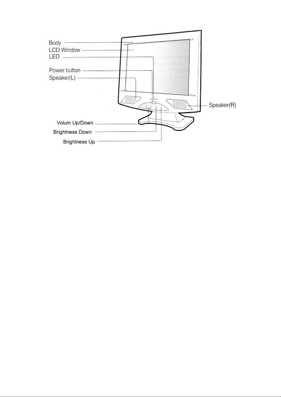
Figure 4-2 Figure 2-2 Control Buttons
Figure 4-3 Figure 2-3
5. 2.3.1. Activity LED
This LED blinks if there is any network activity.
6. 2.3.2. Ethernet LED
This LED lights up only when the unit is connected at 100 Mbps.
7. 2.4. Troubleshooting
Before calling for service, check the information in this section to see if you can solve the problem
yourself. If you do need assistance, please call the phone number on the warranty section.
There is no screen image
• Check to see that the computer is plugged in and turned on.
The screen image is too light or too dark
• Adjust the brightness settings.
8. 2.5. PowerSaver
This monitor has a built-in power management system called PowerSaver. This system saves energy
by switching your monitor into a low-power mode when it has not been used for a certain amount of
time. The monitor automatically returns to normal operation when you move the computer's mouse or
press a key on the keyboard. For energy conservation, turn your monitor OFF when it is not needed,
-- 1414 / 69 / 69 –
Page 15
or when leaving it unattended for long periods. Use the Software section of the manual to set up this
feature
software
9. 3. Software Configuration
The TeleCLIENT TC7370 software includes the TeleCLIENT Setup WizardTeleCLIENT Setup Wizard to assist with the basic setup and software configuration. This
chapter explains how to configure the software. It includes the following sections:
33. • Using the TeleCLIENT Setup Wizard
34. • Resetting TeleCLIENT TC7370 properties
35. • TeleCLIENT Software Update Procedure
10.3.1. Using the TeleCLIENT Setup Wizard
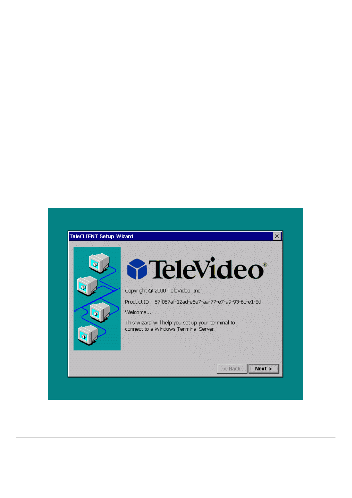
At initial start-up, the TeleCLIENT Setup WizardTeleCLIENT Setup Wizard welcome window will appear to guide you in setting up your network configuration
(Figure 3-1).
Figure 3-1 TeleCLIENT Setup Wizard Welcome Window
To use the TeleCLIENT Setup WizardTeleCLIENT Setup Wizard, complete the following steps:
Note: If the TeleCLIENT stays in that ‘TeleCLIENT Setup Wizard’ welcome window for 30
seconds it will try to configure itself automatically. However, this will require a DHCP server
-- 1515 / 69 / 69 –
Page 16
running on the network.
11. 1. Click Next in the welcome window.
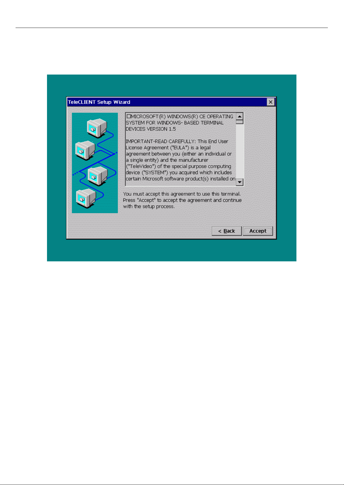
19. 2. Review the End User License Agreement (EULA) (Figure 3-2). If you
agree to the terms of the EULA, click Accept.
Figure 3-2 TeleCLIENT Setup Wizard EULA Window
20. 3. The IP Address window appears (Figure 3-3).
-- 1616 / 69 / 69 –
Page 17
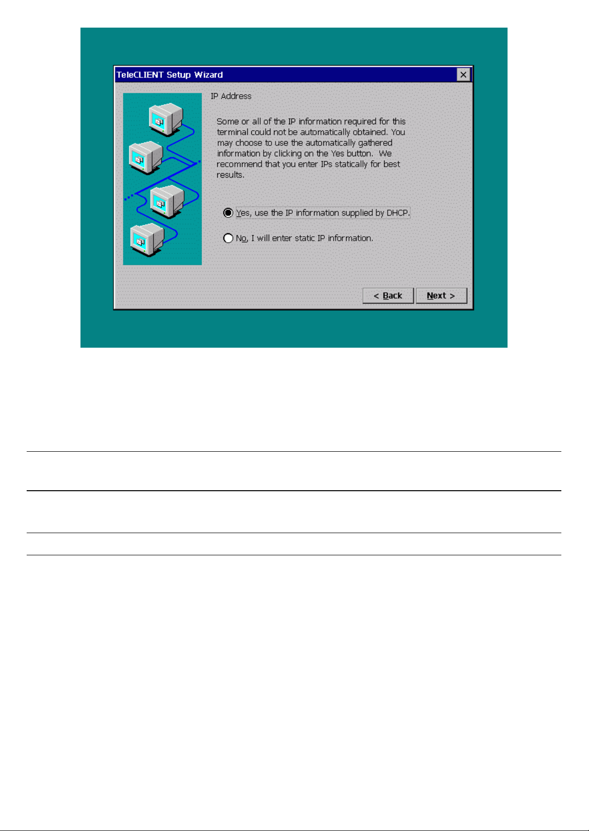
Figure 3-3 TeleCLIENT Setup Wizard IP Address Window
21. 4. In the IP Address window, choose one of the following options:
36. • If your network uses Dynamic Host Configuration Protocol (DHCP), select ‘Yes to use
the IP information provided by DHCP’.
Note: At initial start up, the TeleCLIENT will wait for the DHCP response; If you don’t have
DHCP server on your network click Cancel and proceed with the set up.
37. • If you wish to enter static IP information, select No.
NOTE: If your network uses DHCP, skip Steps 5 through 10.
22. 5. If you selected No, the Specifying an IP Address window appears (Figure
3-4).
-- 1717 / 69 / 69 –
Page 18
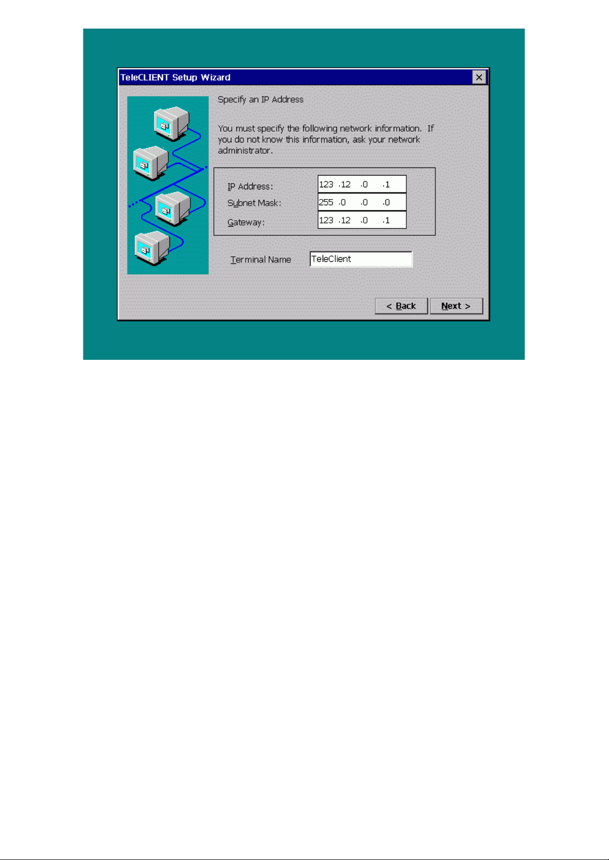
Figure 3-4 TeleCLIENT Setup Wizard Static IP Configuration Window
23. 6. Type in your TeleCLIENT TC7370’s IP address, Subnet Mask, and
Gateway.
24. 7. Assign a terminal name or leave as the default name. Do Not leave it
blank.
25. 8. Click Next. The DNS/WINS window appears (Figure 3-5).
-- 1818 / 69 / 69 –
Page 19
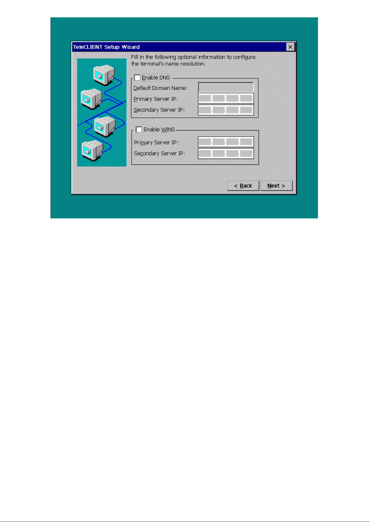
Figure 3-5 TeleCLIENT Setup Wizard DNS/WINS Configuration Window
26. 9. If your network requires DNS settings, select Enable DNS. Enter the
Default Domain Name, Primary Server IP and Secondary Server IP.
27. 10. If your network requires WINS settings, select Enable WINS. Enter the
Primary Server IP and Secondary Server IP.
28. 11. Click Next.
29. 12. The Display Properties window appears (Figure 3-6).
-- 1919 / 69 / 69 –
Page 20
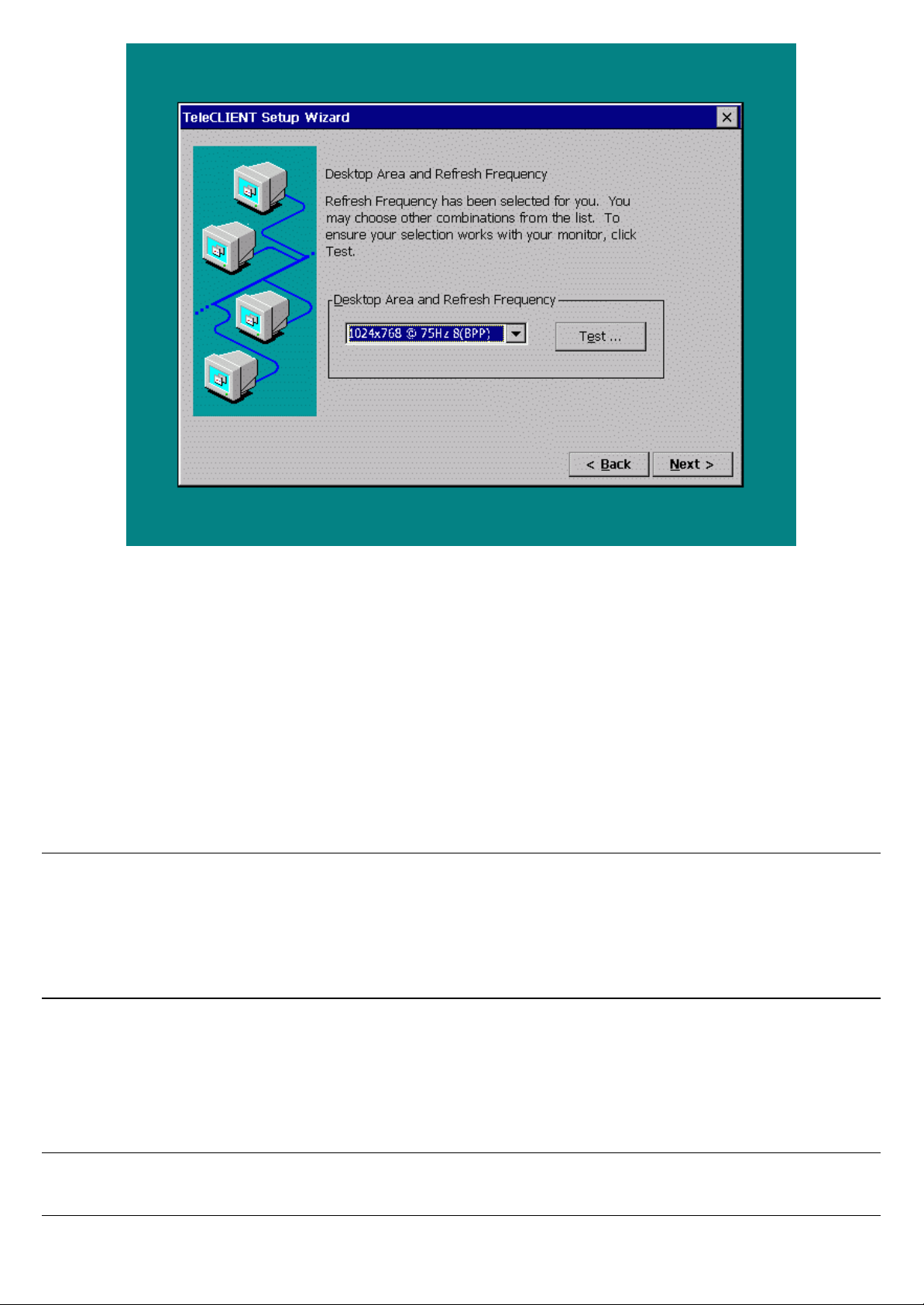
Figure 3-6 TeleCLIENT Setup Wizard Display Properties Window
30. 13. Select a desired resolution and refresh rate from the ‘Desktop Area and
Refresh Frequency’ drop-down menu.
31. 14. To test the selected setting, click Test and follow the direction on the
screen. Otherwise, click Next to skip the testing and go to step 18.
32. 15. Click Yes at the restart prompt.
33. 16. When the Pass or Fail window comes up immediately after the image
testing. Click Pass if the image shows properly. Note that the default
button is Fail. When you click Pass the TeleCLIENT should reboot again.
Note: This only tests the selected setting but does not change the setting. After completing this test,
the user will be brought back to the welcome screen. User should simply follow steps from step 1
again. When you get to the display setting for the second time the resolution and frequency setting
should have gone back to the default setting; user should pick the desired setting again before
pressing NEXT.
34. 17. Repeat the steps from step 1. Notice that this time around the display
setting is changed to the selected setting. Click Next.
35. 18. Click OK when the message, “You have not tried these new
settings…Choose OK.”
Note: To go back to configuring the terminal’s monitor settings, press the F2 key at the Connection
Manager screen, click the Display tab, and begin at step 1 above.
-- 2020 / 69 / 69 –
Page 21
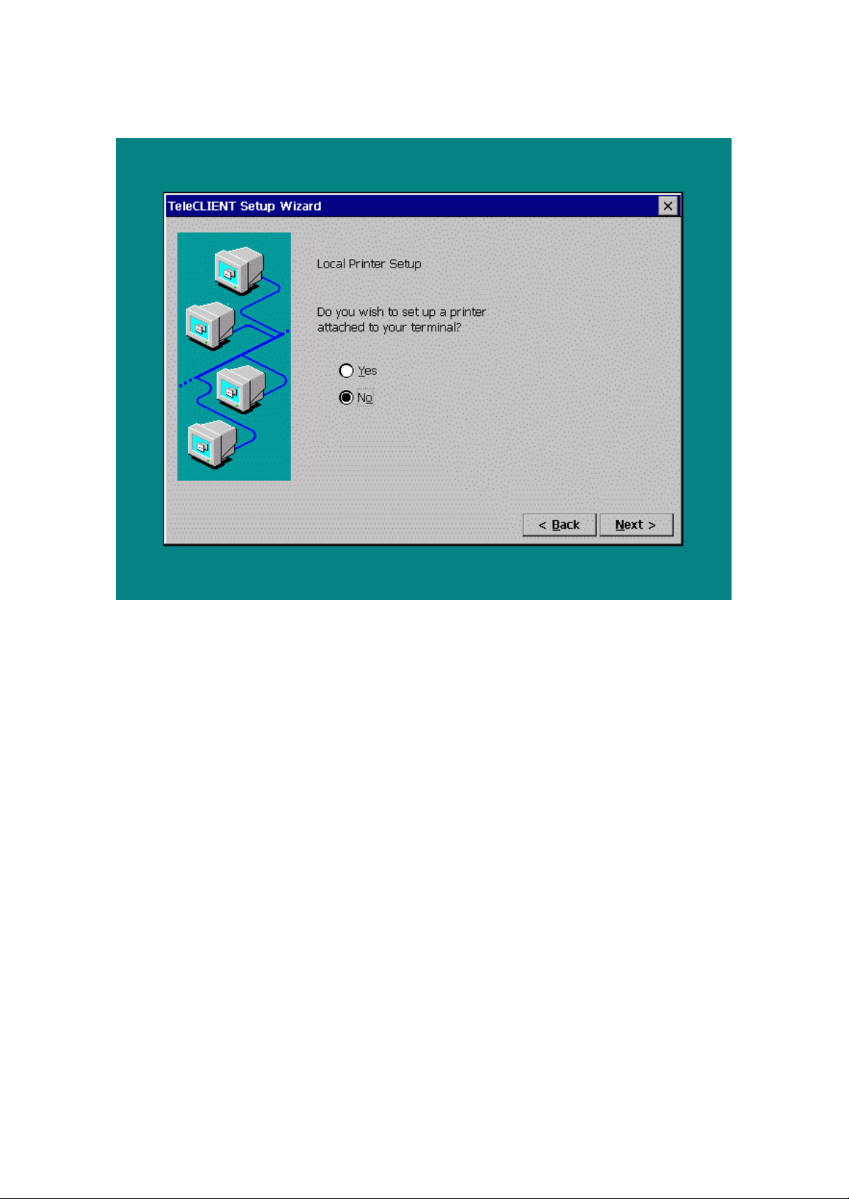
36. 19. Local Printer Setup option window appears (Figure 3-7).
37. 20. If a local printer is connected to the parallel/printer port select ‘Yes’, then
click Next. Otherwise, select ‘No’ and click Next, then go to step 27.
Figure 3-7 Local Printer Setup
38. 21. Select the printer port then click Next (Figure 3-8).
-- 2121 / 69 / 69 –
Page 22
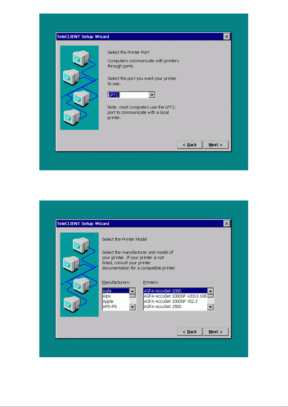
Figure 3-8 Select Printer Port
39. 22. Select the printer manufacturer and the model number (Figure 3-9).
Figure 3-9 Select the Printer Model
40. 23. Name the printer and click Next (Figure 3-10).
-- 2222 / 69 / 69 –
Page 23
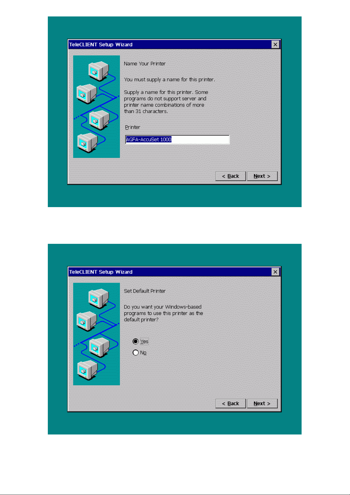
Figure 3-10 Printer Name
41. 24. Select if this printer will be used as the default printer (Figure 3-11).
Figure 3-11 Set Default
42. 25. Select if you want to configure another printer (Figure 3-12).
-- 2323 / 69 / 69 –
Page 24
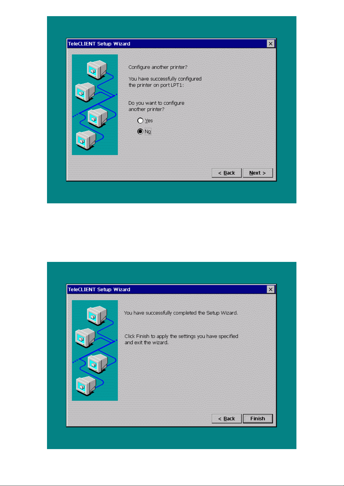
Figure 3-12 Additional Printer Configuration
43. 26. If you clicked ‘Yes’ go back to step 20. Otherwise, proceed to step 27.
44. 27. Click Next. The ‘TeleCLIENT Setup Wizard Finish’ window appears
(Figure 3-13).
-- 2424 / 69 / 69 –
Page 25
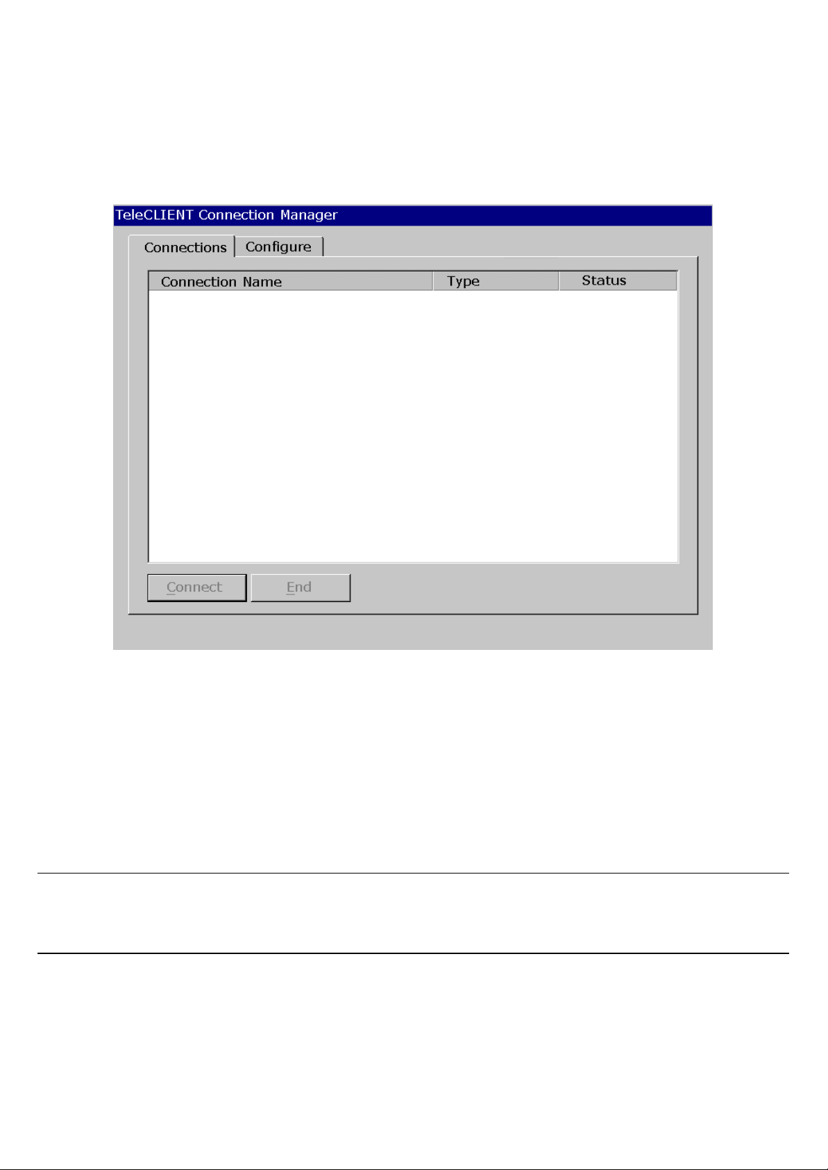
Figure 3-13 TeleCLIENT Setup Wizard Finish Window
45. 28. To save the configuration settings, click Finish.
46. 29. Once the settings have been saved, follow the prompts to restart the
TeleCLIENT TC7370. After the TeleCLIENT TC7370 has restarted, the
TeleCLIENT Connection Manager window appears (Figure 3-14).
Figure 3-14 TeleCLIENT Connection Manager Window
You are now ready to create network connections and connect to the network. Refer to Chapter 4Chapter 4 – TeleCLIENT TC7370 OperationTeleCLIENT TC7370 Operation for
instructions.
12.3.2. Setting TeleCLIENT TC7370 Properties
You can reset the TeleCLIENT TC7370 properties by starting the TeleCLIENT Terminal PropertiesTeleCLIENT Terminal Properties window.
NOTE: When making changes in the TeleCLIENT Terminal Properties window, click OK to set the
new values. Click X at any time to return to the TeleCLIENT Connection Manager window (Figure
3-14).
The TeleCLIENT Terminal Properties window includes the following tabs:
38. • General
Displays product, copyright information and also used to reset to factory defaults.
39. • Input
-- 2525 / 69 / 69 –
Page 26
Used to configure the TeleCLIENT TC7370 keyboard, mouse and character repeat
settings.
40. • Display
Used to configure the TeleCLIENT TC7370 display settings.
41. • Network
Used to configure the TeleCLIENT TC7370 network settings.
42. • Printers
Used to install and configure the printer settings for RDP sessions.
43. • System
Used to change client configuration and update
44. • Management
Used to update TeleCLIENT Management Software, configure SNMP agent, and control
audio output.
45. • NetInfo
Used to display the network settings.
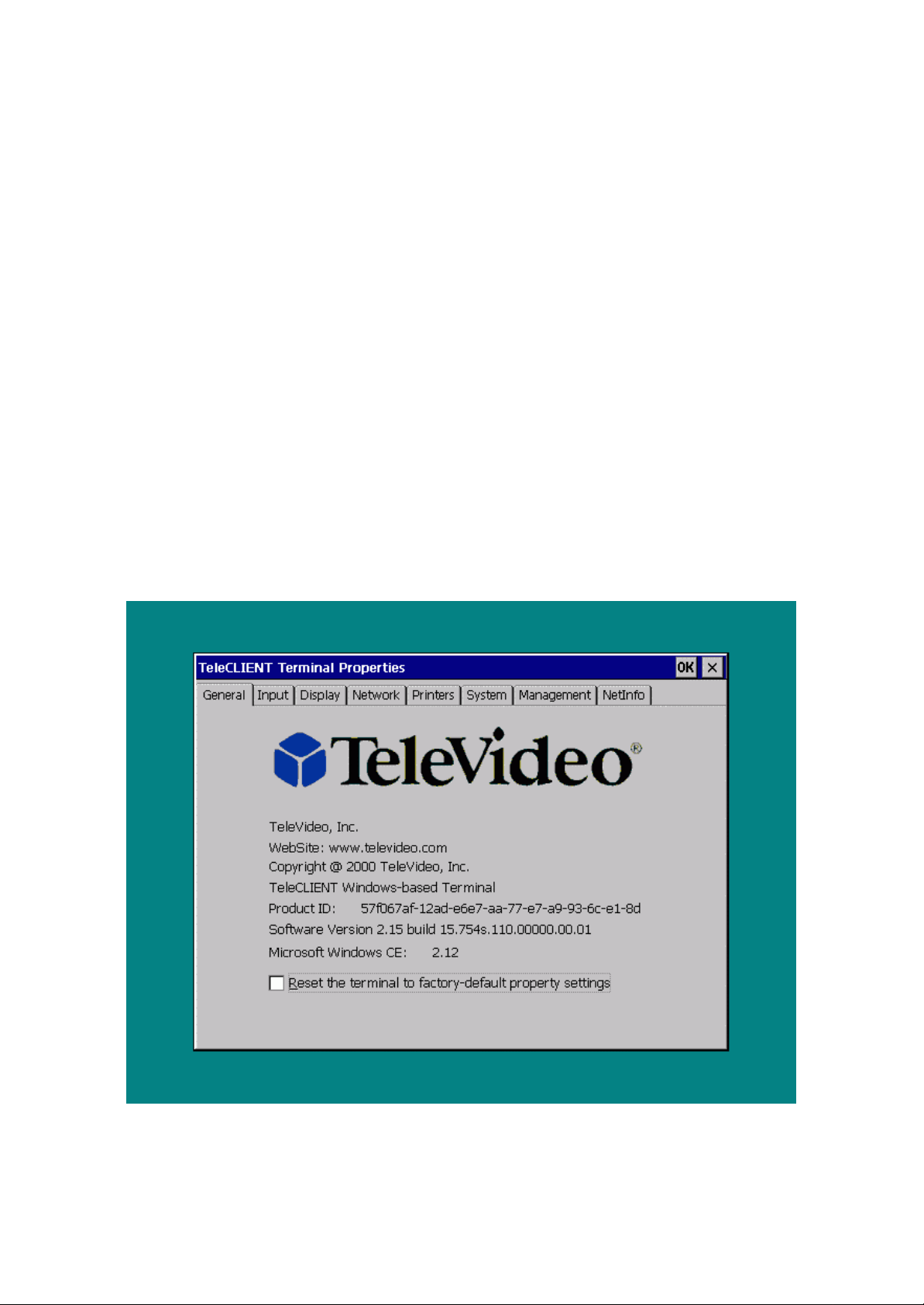
To start the TeleCTeleCLIENT Terminal PropertiesLIENT Terminal Properties while the TeleCLIENT Connection ManagerTeleCLIENT Connection Manager is displayed, Press <F2F2> on the TeleCLIENT
TC7370 keyboard. The TeleCLIENT Terminal PropertiesTeleCLIENT Terminal Properties window will appear (Figure 3-15).
Figure 3-15 TeleCLIENT Terminal Properties – General Tab
13.3.2.1. Resetting the TeleCLIENT TC7370 to Factory Defaults
To restore the factory default settings, complete the following steps:
-- 2626 / 69 / 69 –
Page 27
14. 1. Select the General tab (Figure 3-15).
To change your keyboard's locale, click the down arrow in the ‘Locale’ field.
47. 2. Check the ‘Reset the TeleCLIENT to factory-default property settings’
checkbox.
48. 3. Click Yes when prompt.
Note: When you restart the TeleCLIENT TC7370 after resetting the factory defaults, you must use
the setup wizard again. Refer to Section 3.1 - Using the TeleCLIENT Setup Wizard.
15.3.2.2. Setting Keyboard Characteristics
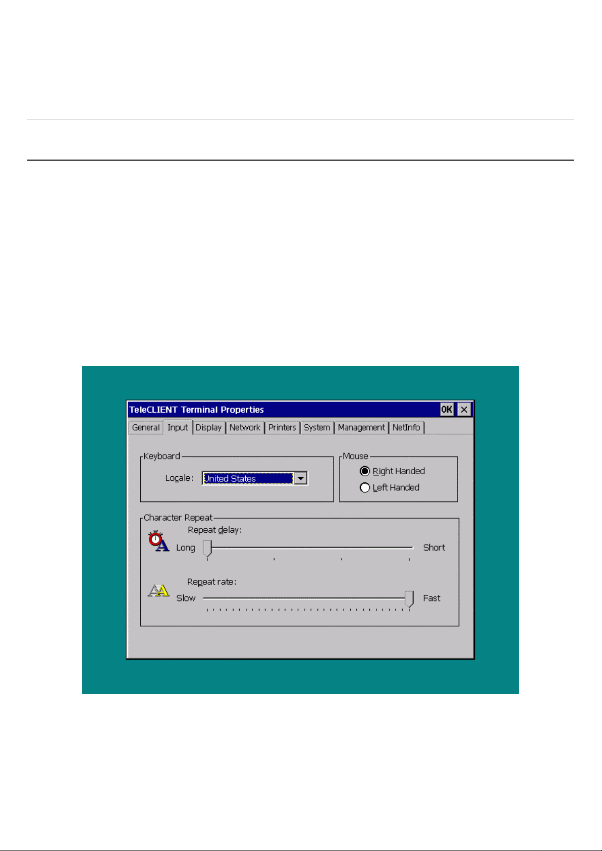
You can change the following keyboard characteristics to match your own keyboard and typing habits:
46. • Keyboard Locale - The language used by the keyboard.
47. • Character Repeat - The repeat delay of a keyboard character (i.e., length of time
elapsed before a character is repeated when a key is pressed).
48. • Repeat Rate - The rate at which the keyboard repeats characters.
To change these keyboard characteristics, complete the following steps:
16. 1. Select the Input tab in the TeleCLIENT Terminal Properties window (Figure3-16).
Figure 3-16 TeleCLIENT Terminal Properties – Input Tab
49. 2.
Select a language from the available options.
50. 3. To change your mouse, click Right-handed or Left-handed. If no mouse
settings are selected, the TeleCLIENT Terminal Properties window defaults
-- 2727 / 69 / 69 –
Page 28
to Right-handed.
51. 4. To change the repeat delay, use the mouse to drag the ‘Repeat Delay’
slider left or right.
52. 5. To change the repeat rate, use the mouse to drag the Repeat Rate slider
left or right.
53. 6. Click OK.
17.3.2.3. Setting Display Characteristics
You can change the TeleCLIENT TC7370’s display characteristics and screen saver settings to
match your own preferences
Changing the Desktop Area and Refresh Frequency
To change display settings, complete the following steps:
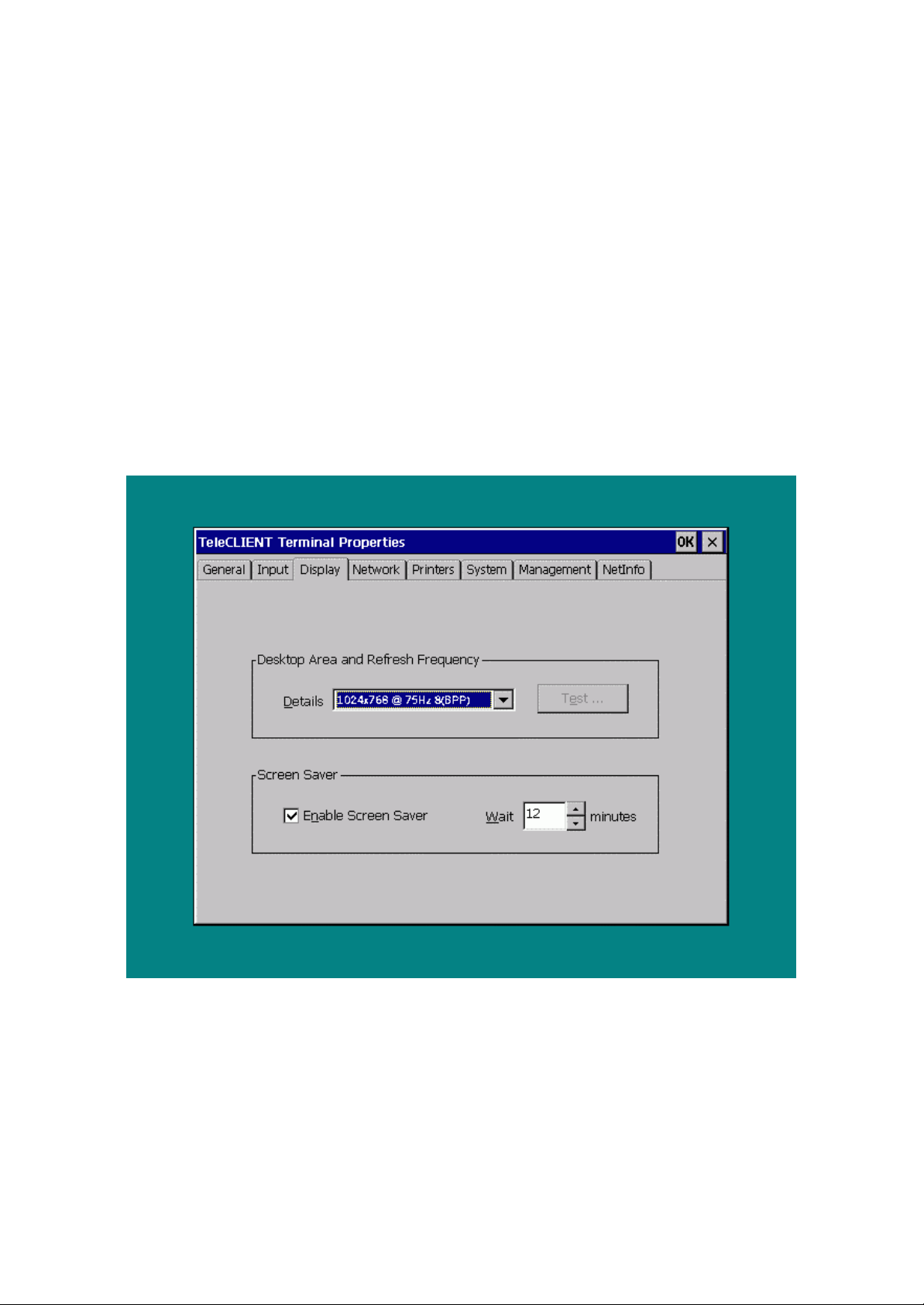
18. 1. Select the Display tab in the TeleCLIENT Terminal Properties window (Figure 3-17).
Figure 3-17 TeleCLIENT Terminal Properties – Display Tab
54. 2. The Desktop Area and Refresh Frequency field displays the current
TeleCLIENT TC7370 display resolution. To change the resolution, click the
down arrow and select a setting from the list of options.
55. 3. To test the selected setting, click Test and follow the direction on the
screen. If you wish not to test click OK to go back to connection manager
and disregard the next steps.
56. 4. Click OK at the restart prompt.
-- 2828 / 69 / 69 –
Page 29
57. 5. When the Pass or Fail window comes up immediately after the image
testing. Click Pass if the image shows properly. Note that the default
button is Fail. When you click Pass the TeleCLIENT should reboot again.
58. 6. Click OK.
Setting Screen Saver
To set screen saver complete the following steps:
19. 1. Make sure the ‘Enable Screen Saver’ box is checked.
Warning: Screen saver must be enabled to activate the Energy Star® energy conservation mode.
59. 2. To set the time TeleCLIENT TC7370 waits before activating the screen
saver, enter the new value in the Wait field (or use the up and down arrows).
The defau lt wait value is 12 minutes.
60. 3. Click OK.
20.3.2.4. Changing Network Settings
In addition to changing the network settings by resetting the factory defaults and using the setup wizard again, you can also use the
TeleCLIENT Terminal ProperTeleCLIENT Terminal Propertiesties window for this task.
To change network settings, complete the following steps:
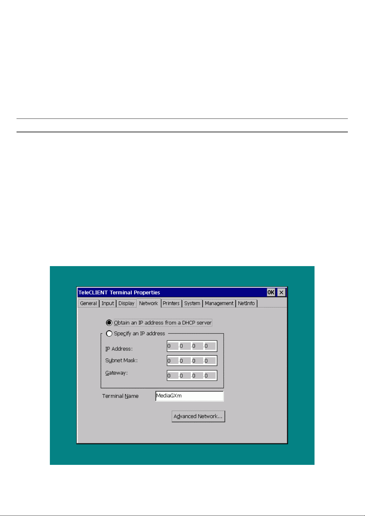
21. 1. Select the Network tab in the TeleCLIENT Terminal Properties window (Figure 3-18).
Figure 3-18 TeleCLIENT Terminal Properties – Network Tab
-- 2929 / 69 / 69 –
Page 30
61. 2. To enable DHCP addressing, select ‘Obtain an IP address from a DHCP
server’.
62. 3. To specify an IP address, select ‘Specify an IP address’. Then enter the
following information:
49. • IP Address
50. • Subnet Mask
51. • Gateway
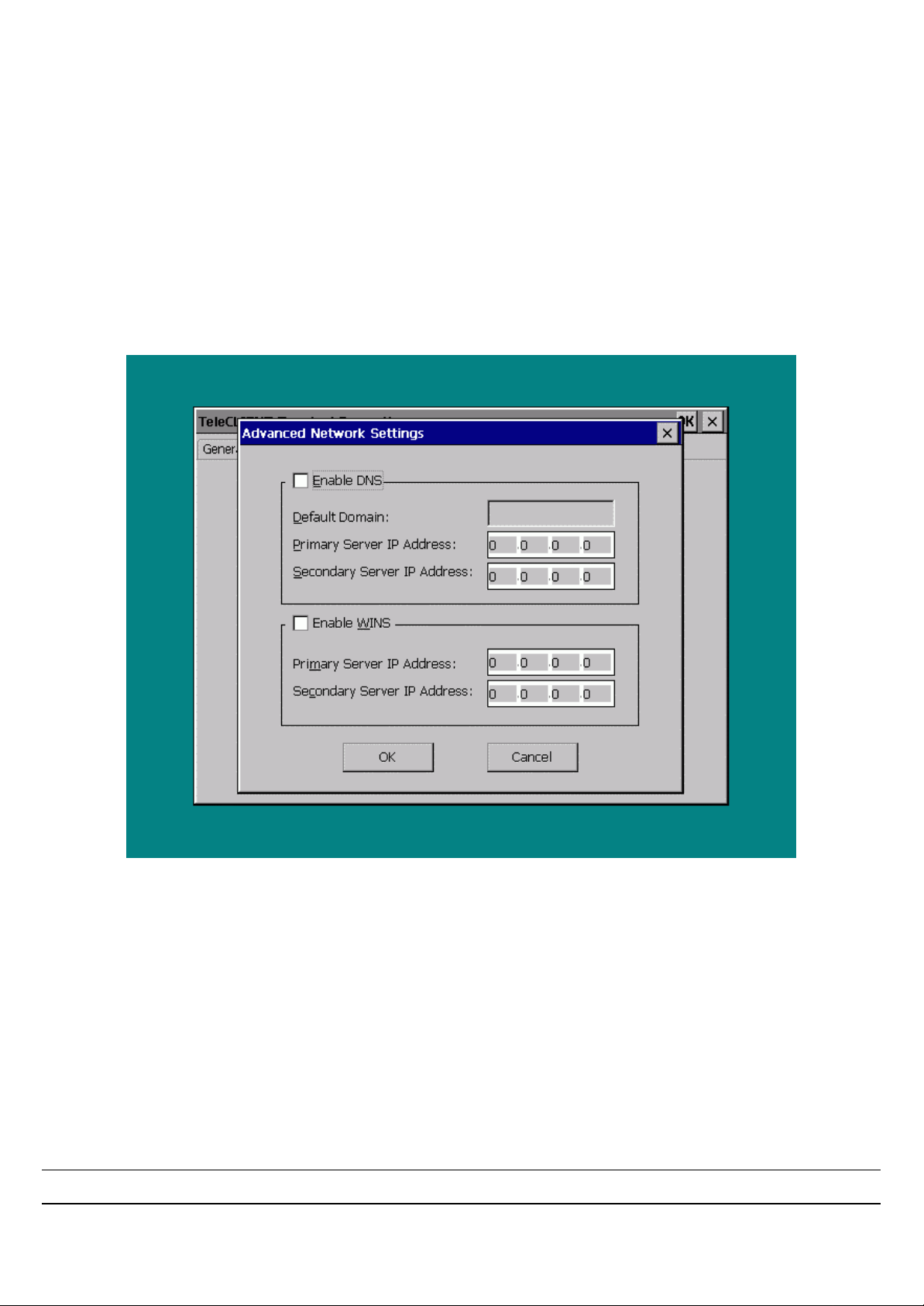
63. 4. To enable DNS and/or WINS services, click Advanced Network button
(Figure 3-19).
Figure 3-19 TeleCLIENT Terminal Properties – Advanced Network Settings
52. • If your network requires DNS settings, select ‘Enable DNS’. Enter the Default
Domain Name, Primary Server IP and Secondary Server IP.
53. • If your network requires WINS settings, select ‘Enable WINS’. Enter the Primary
Server IP and Secondary Server IP.
64. 5. Click OK.
22.3.2.5. Printer Settings
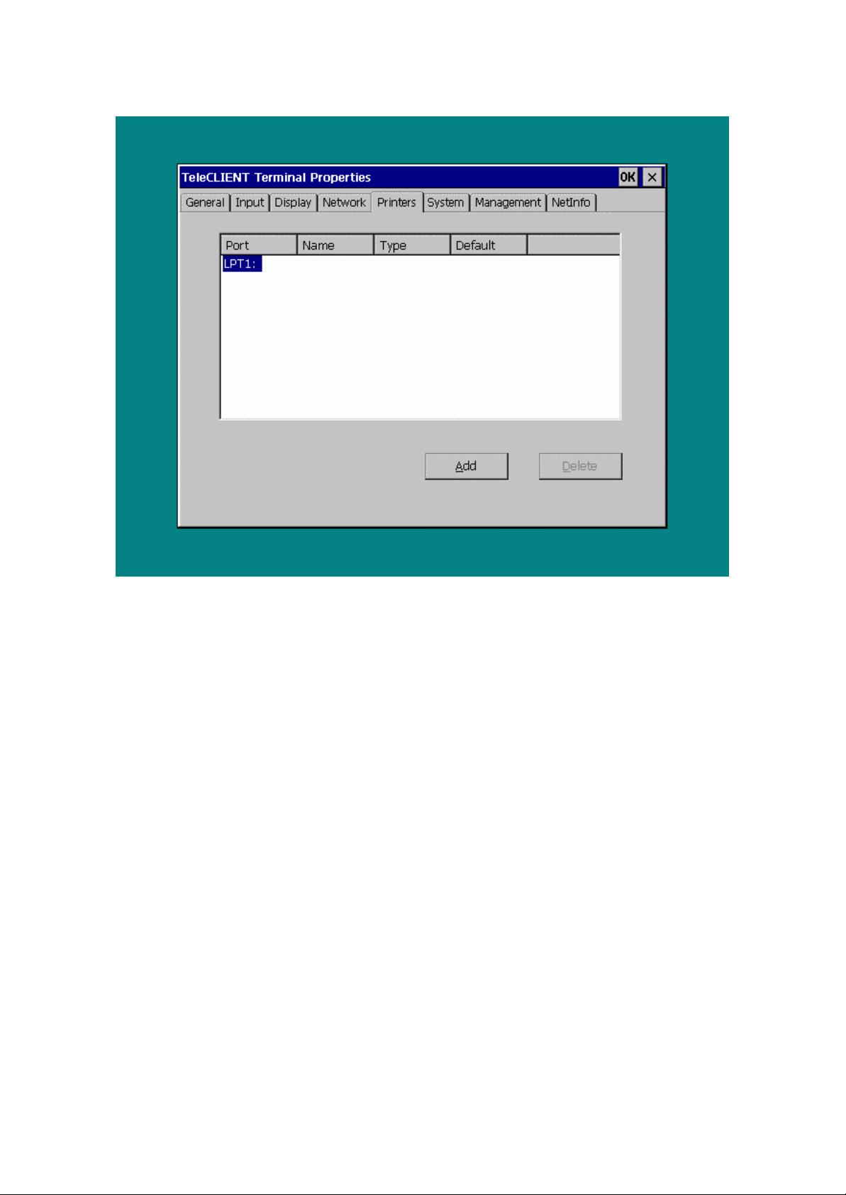
The PrinterPrinter tab provides the option to choose and load the proper printer driver
Warning: Make sure the printer is properly connected to the TeleCLIENT TC7370
-- 3030 / 69 / 69 –
Page 31
To add a printer complete the following steps:
23. 1. Select the Printers tab in the TeleCLIENT Terminal Properties window (Figure3-20).
Figure 3-20 TeleCLIENT Terminal Properties – Printers Settings
65. 2. Select the port and click Add.
66. 3. On the Printer Properties window, type in the desired name for the printer
then select the manufacturer of the printer and the model using the scroll-bar
(Figure 3-21).
-- 3131 / 69 / 69 –
Page 32
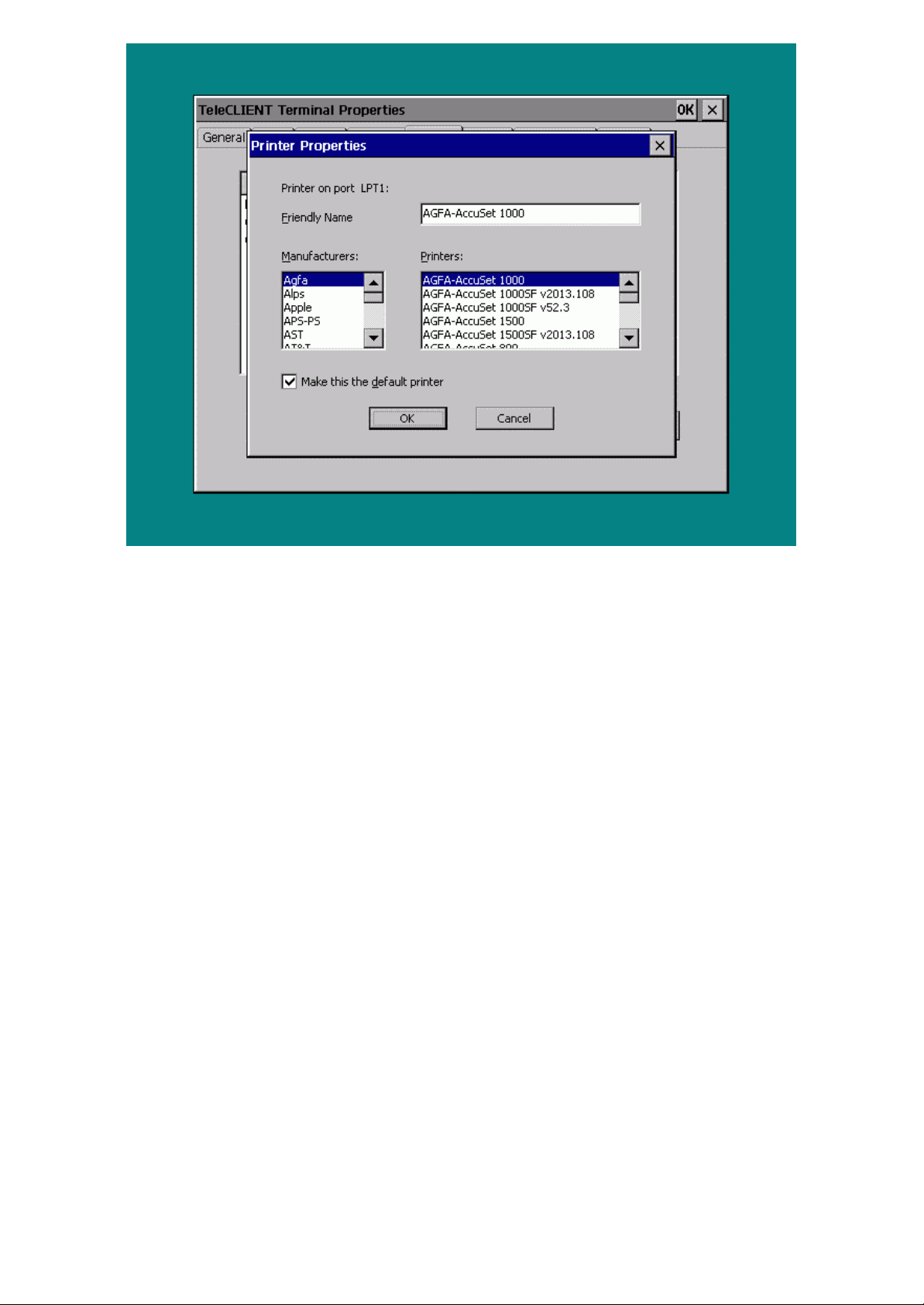
Figure 3-21 Printer Properties
67. 4. Check or uncheck the default printer option then click OK.
68. 5. Verify that the name, type, and the default status are correct, and then
click OK.
To change the printer settings complete the following steps:
24. 1. Select the Printers tab in the TeleCLIENT Terminal Properties window.
69. 2. Click Properties.
70. 3. On the Printer Properties window, type in the desired name for the printer
then select the manufacturer of the printer and the model using the scroll-bar.
Click OK.
71. 4. Verify that the name, type, and the default status are correct, and then
click OK.
To delete a printer complete the following steps:
25. 1. Select the Printers tab in the TeleCLIENT Terminal Properties window.
72. 2. Click Delete.
73. 3. Click Yes when prompt.
74. 4. Click OK.
26.3.2.6. Changing System Settings
The SystemSystem tab presents system memory information. It also lets the developer update the memory statistics of the client terminal. It also
-- 3232 / 69 / 69 –
Page 33
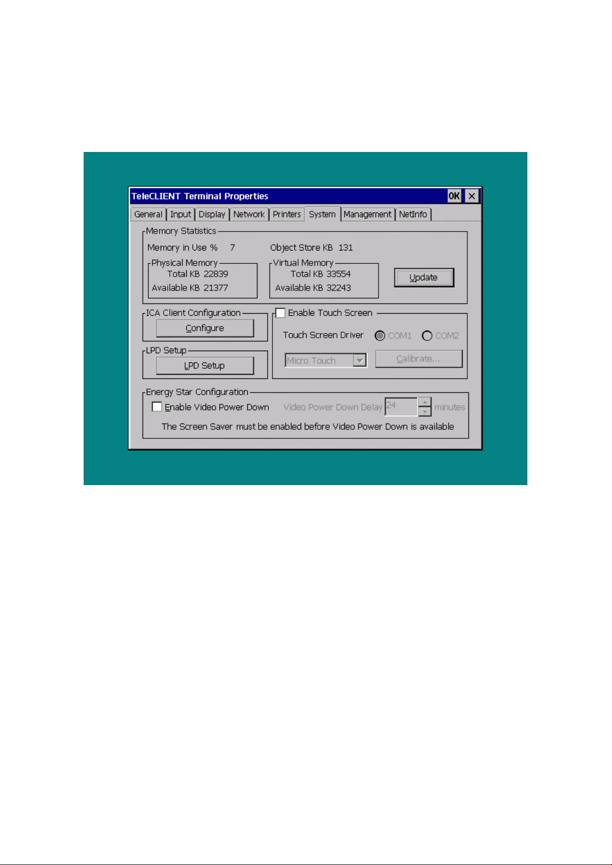
allows the user to:
54. • Edit ICA client configuration.
55. • Disable/enable energy saving Video Power Down.
To make these changes click on the System tab in the TeleCLIENT Terminal Properties (Figure 3-
22).
Figure 3-22 TeleCLIENT Terminal Properties – System Tab
To change the ICA client configuration:
27. 1. Click Configure in the ICA Client Configuration field to set global settings (Default hot
keys, Preferences, Server Location) for TeleCLIENT TC7370 (ICA only) (Figure 3-23).
-- 3333 / 69 / 69 –
Page 34
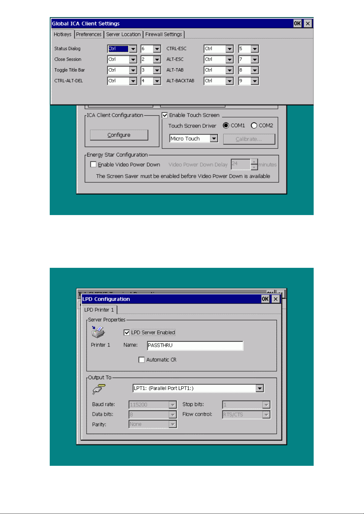
Figure 3-23 ICA Client Configuration
To configure LPD (Line Printer Daemon) settings
28. 1. Click LPD Setup (Figure 3-24).
Figure 3-24 LPD Configuration
-- 3434 / 69 / 69 –
Page 35

Note: LPD can be used only with the LPT port of a TeleCLIENT.
75. 2. Check ‘LPD Server Enabled box’.
76. 3. Enter Printer Name
Note: The name of the printer is a virtual port. Virtual port is a logical device assigned when you set
up LPD services on your server. The default for this field is PASSTHRU. The Printer Name is case
sensitive field.
To enable touch screen
29. 1. Check the ‘Enable Touch Screen’ box.
77. 2. Choose the communication port the touch screen is connected to.
78. 3. Use the drop down menu to choose the manufacturer.
56. • If you have an Elo Touchsystems screen you must click Calibrate and proceed with
the calibrating the screen.
Note: System must be rebooted after checking the ‘Enable Touch Screen’ to calibrate the screen.
57. • If you have a MicroTouch systems screen calibrating is not necessary.
Changing the Energy Star Configuration Settings
To change the energy conservation settings, complete the following steps:
Note: To enable the conservation settings the screen saver must be enabled first
30. 1. To enable the screen saver feature, select the Display tab and check the ‘Enable Screen
Saver’ box
Note: Both features are enabled at default setting.
79. 2. To set the time TeleCLIENT TC7370 waits before activating the screen
saver, enter the new value in the Wait field (or use the up and down arrows).
The default wait value is 24 minutes.
Note: If the energy conservation set time is less than the screen saver set time than the terminal will
automatically detect it and set both times at equal value. In this case the power down mode will
override the screen saver, and it will skip the screen saver and the power down mode will activate.
80. 3. Click OK.
81. 4. Now go back to the System tab and select the ‘Enable Video Power
Down’ box.
82. 5. Set desired wait time.
83. 6. Click OK.
-- 3535 / 69 / 69 –
Page 36
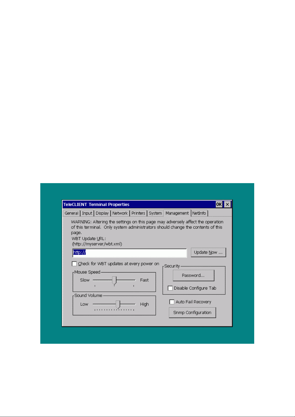
31.3.2.7. Viewing Management Settings
Using the ManagementManagement tab you can:
58. • Update the TeleCLIENT firmware
59. • Control mouse speed.
60. • Control sound volume.
61. • Create or enter password to restrict or allow user to modify a TeleCLIENT Terminal
Properties.
62. • Disable/enable Configure tab in Connection Manager.
63. • Set Auto Fail Recovery option.
64. • Set SNMP settings.
To update the client software
32. 1. Refer to section 3.3 TeleCLIENT Software Update.
To change management settings:
33. 1. Select the Management tab in the TeleCLIENT Terminal Properties window (Figure 3-25).
Figure 3-25 TeleCLIENT Terminal Properties –Management Tab
To adjust the Mouse Speed:
34. 1. Use the Mouse Speed slider bar to adjust speed Slow or Fast
-- 3636 / 69 / 69 –
Page 37
To adjust the Sound Volume:
35. 1. Use the Sound Volume slider bar to adjust volume Low or High.
To create or enter a password:
This feature disables users from making changes to terminal properties.
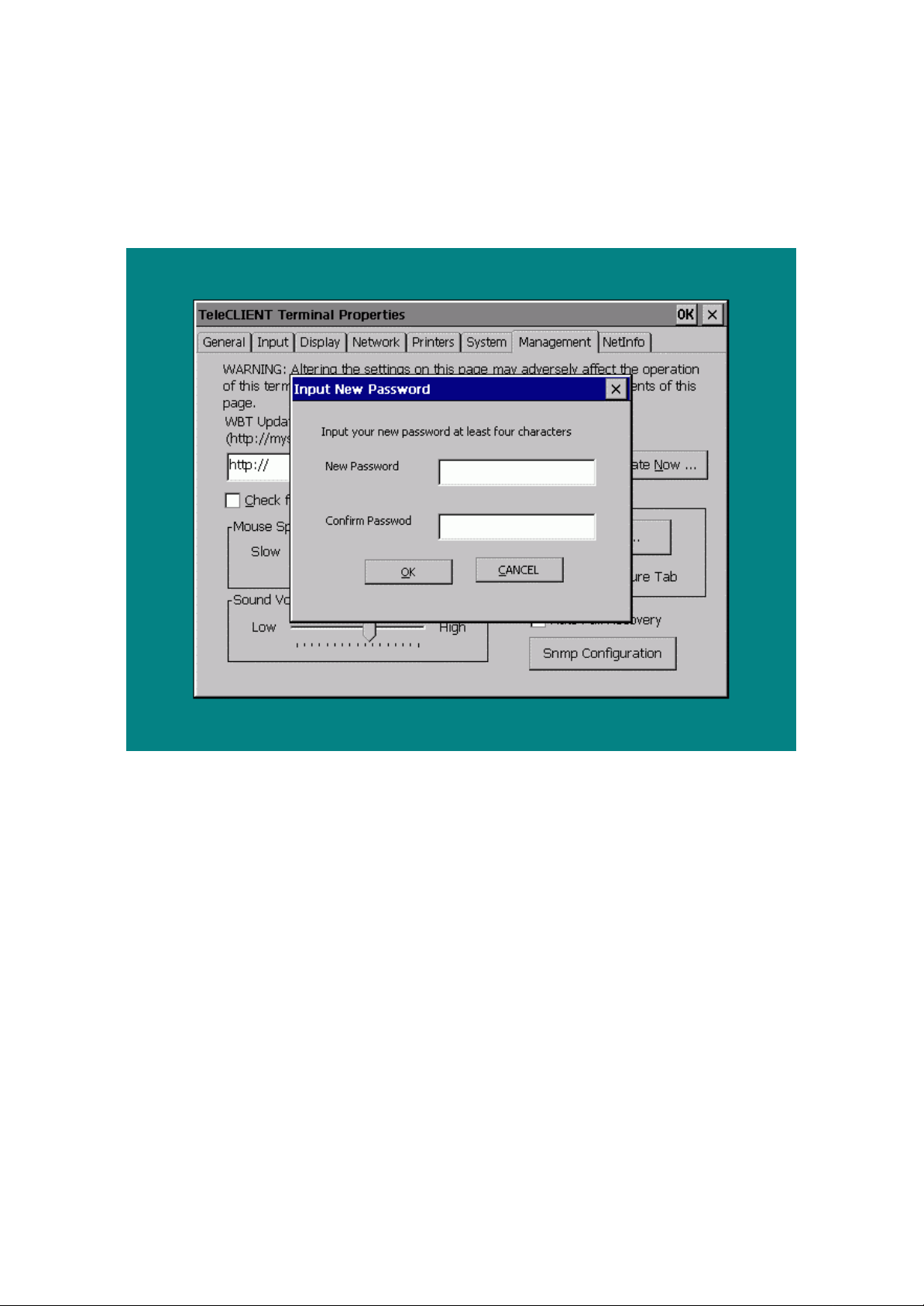
36. 1. Click on Password (Figure 3-26).
Figure 3-26 New Password Input Dialog Box
84. 2. Type in the new password.
85. 3. Confirm the new password.
86. 4. Click OK.
To disable the Connection Manager Configure tab:
This feature disables users from changing connection settings.
37. 1. Select ‘Disable Configure T ab’ box.
To have the client check for an update on every power-on:
38. 1. Type in the URL of the server to check from.
87. 2. Check the ‘Check for WBT updates at every power on’.
88. 3. Click OK.
To bypass the Connection Manager screen for users:
-- 3737 / 69 / 69 –
Page 38
39. 1. In order to have users from changing the connection configuration, enable the Auto Fail
Recovery’ option by checking the option.
To set the SNMP software settings
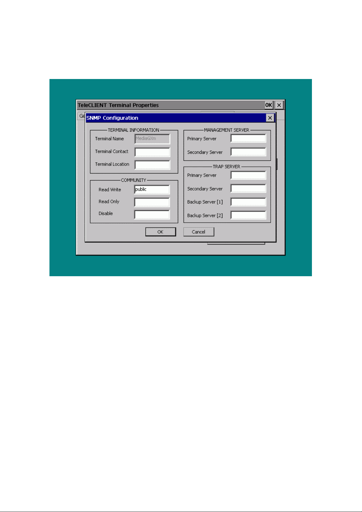
40. 1. Click SNMP Configuration (Figure 3-27).
Figure 3-27 SNMP Configuration
89. 2. Terminal Name is defaulted to the name given under the Network tab only.
90. 3. Enter the contact for the terminal (usually the user of the terminal) and the
location.
91. 4. Community section refers to the SNMP group definition. Enter the group
name.
92. 5. Enter all the necessary and appropriate server names in each category.
93. 6. Click OK.
41.3.2.8. Viewing the Network Information
Using the NetInfo tab you can view and test the network settings.
To view the network properties:
42. 1. Click the NetInfo tab (Figure 3-28).
-- 3838 / 69 / 69 –
Page 39
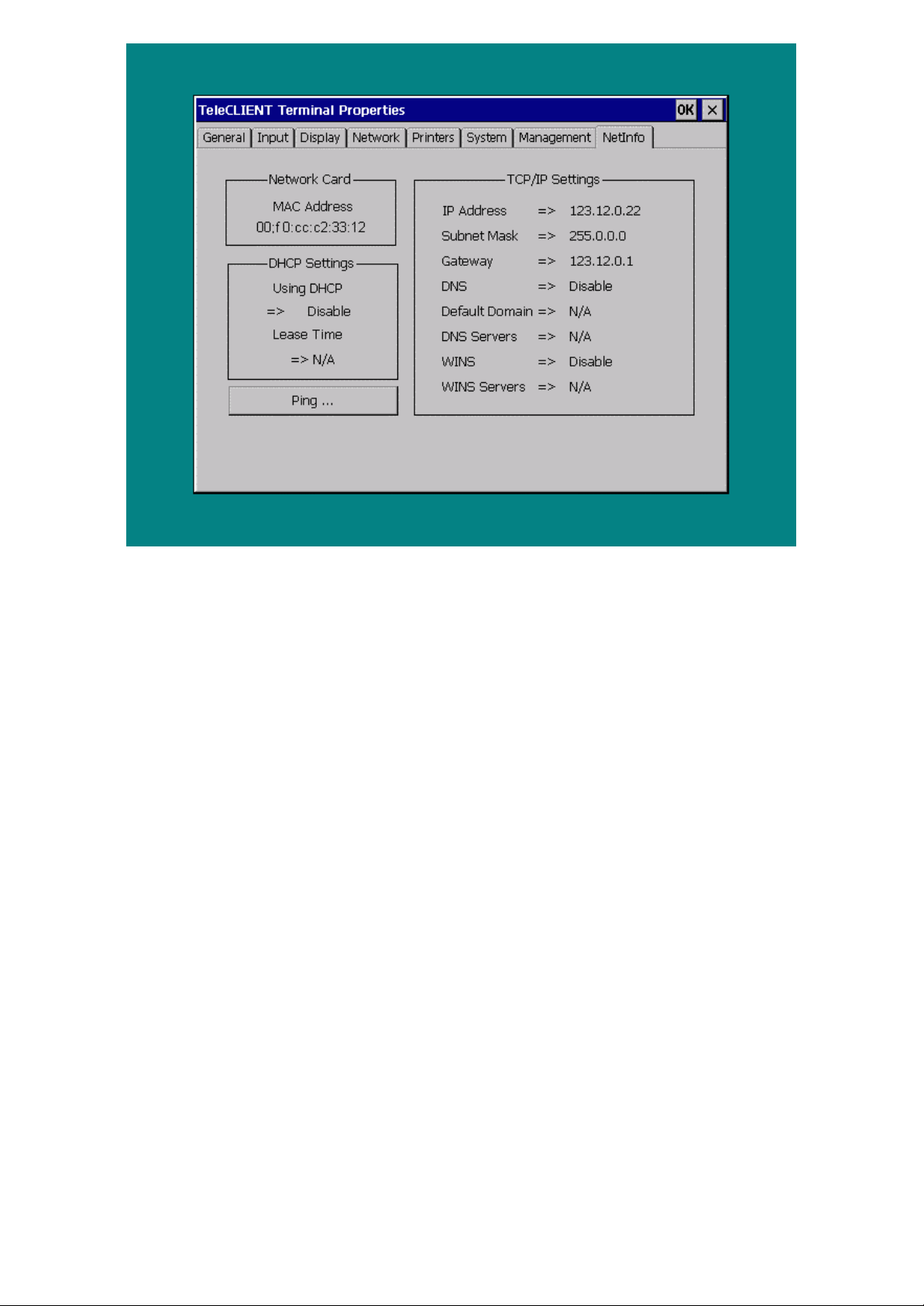
Figure 3-28 TeleCLIENT Terminal Properties –Network Information Tab
To test the network connection
43. 1. Click Ping… (Figure 3-28).
94. 2. Enter the server IP address you are trying to connect, then click Ping
(Figure 3-29)
-- 3939 / 69 / 69 –
Page 40
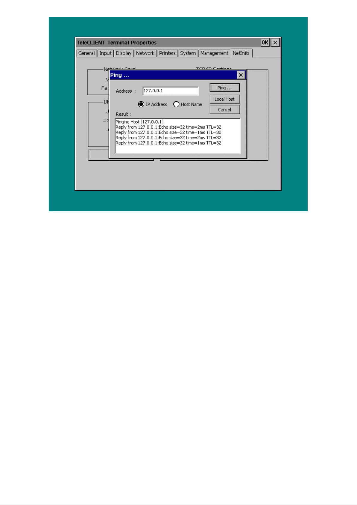
Figure 3-29 Ping Usage
95. 3. Or, choose the ‘Host Name’ and enter the server name, then click Ping….
96. 4. Click Local Host to check the TeleCLIENT’s network operability.
97. 5. Click X or Cancel to exit.
44.3.3. TeleCLIENT™ Software Update
45.3.3.1. Overview
A TeleCLIENT software update consists of the following:
65. • Checking a server for a newer version of operating system software
66. • Downloading and installing any software that is newer than the software currently
running on TeleCLIENT
67. • Rebooting with the new OS
A TeleCLIENT operating system includes the CE operating system and TeleCLIENT applications as
a whole. A software update can be performed manually at TeleCLIENT or automatically every time
TeleCLIENT is power cycled.
A software update performs the following three steps:
46. 1. A software update package file is downloaded by TeleCLIENT. This file describes the
software that needs to be downloaded, where those files reside on the network, and an ID,
which the package checks against a local history of installed packages.
98. 2. If the ID of the downloaded package indicates that the update has not
-- 4040 / 69 / 69 –
Page 41

been executed, the directives contained in the package file are executed.
99. 3. After the successful application of the update directives, the ID of the
package is stored in the local history log of installed packages.
Update package files allow TeleCLIENT to quickly see if new software needs to be downloaded. By
comparing the ID of the package against a local history log, TeleCLIENT can determine if a software
update needs to be performed.
47.3.3.2. TeleCLIENT Setup Property Page
Figure 3-25 illustrates the Management tab, which displays the support for TeleCLIENT software
update functionality. The property page components are as follows:
68. • Edit Box: Contains the Uniform Resource Locator (URL) for the update package
used by TeleCLIENT for software updates. Supported protocols are http:// and ftp://.
69. • Update Now… button: Used to immediately perform a manual software update,
using the indicated URL.
Note: This will force a reset of the terminal.
70. • Checkbox: Used to set TeleCLIENT so that it checks the URL for a software update
every time TeleCLIENT is power cycled.
A Standard Upgrade of the Operating System
The following is the update package XML file. This example upgrades the Windows CE image on
the boot partition of the DOC. The XML code directs the update software package to load a
Windows CE image into the DiskOnChip boot partition.
This update example operates by loading the OS image into RAM then writing the image to the DOC.
It is critical when writing to the DOC the update runs to completion. If only a partial image is
uploaded TeleCLIENT will not boot and the parallel port will have to be used to update the image.
Ensure that the image be small enough to fit in the boot partition and still have enough space to
accommodate the persistent registry. If the image to be loaded is larger than the boot partition,
TeleCLIENT will not boot. Example 2 illustrates how to overcome this limitation.
< Package ID= "WBT 1.2" >
<CopyFile OSImage="Yes" OSImageSize="5700000">
<Description>Windows CE 2.11 Update</Description>
<Source>http://Server_name/ceimage.rom</Source>
<Destination>\Program Files \ceimage.rom</Destination>
</CopyFile>
<Reboot/>
</Package>
-- 4141 / 69 / 69 –
Page 42

Error! Reference source not found. 1 explains the directives used in this sample:
Table 1. Directives Used in Simple OS Upgrade
Directive Description
ID="WBT 1.2" Adds a unique ID to the update.
The ID string is read by the client and checked against an
ID stored locally. If the ID’s match the update is skipped.
If the ID’s do not match the update is attempted. If the ID
is left blank “<Package>” the update always attempted.
<CopyFile> Copy a file to the client
OSImage=“YES” The file is an OS image and to be stored on the DOC
OSImageSize=“5700000” Size of the file to be downloaded, this is used when
allocating temporary RAM storage for the new CE image.
<Description> String displayed on TeleCLIENT when the update is
running.
<Source> Location of ceimage.rom.
This file must be located in the directory specified by the
source path (Server_name).
NOTE: Use the bintodoc /r 100 command to process the
nk.bin.
<Destination> The location on the CE device where the temporary image
will be stored.
<Reboot> Forces a reboot of TeleCLIENT.
Formatting the DiskOnChip and Upgrading the Operating System
When the partition size is not large enough to contain the Windows CE image and the persistent
registry, the DOC will need to be reformatted before installing the new image. This operation is riskier
then Example 1. If power is lost during the format operatio n, the DOC may be corrupted and will
have to be removed from TeleCLIENT and formatted on a separate machine. After the format
operation an interrupt in the update procedure will result in a corrupt CE image on the DOC. If the
image on the DOC is corrupted a new image will have to be uploaded via the parallel port.
After successfully updating and rebooting, the user may be prompted by a dialog that offers to
reformat the DOC file system storage. It is recommended the user accept the reformat operation.
<Package ID="WBT 1.2">
-- 4242 / 69 / 69 –
Page 43

<CopyFile Execute="Yes" WaitForExit="Yes">
<Description>Format DOC</Description>
<Source>http://Server_name/dformat.exe</Source>
<Destination>\Program Files \dformat.exe</Destination>
<CommandLine>-w:0xd2000 -s:! -l:0x600000 -
n:BIPO</CommandLine>
</CopyFile>
<DiskOnChipOsUpdate>
<Description>Windows CE 2.11 Update</Description>
<Source>http://Server_name/ceimage.rom</Source>
</DiskOnChipOsUpdate>
<Reboot/>
</Package>
Table 2. Directives Used in DOC Format and OS Upgrade
Directives Description
ID="WBT 1.2" Adds a unique ID to the update.
The ID string is read by the client and checked against
an ID stored locally. If the ID’s match the update is
skipped. If the ID ’s do not match the update is
attempted. If the ID is left blank “<Package>” the
update always attempted.
<CopyFile > Copies a file to TeleCLIENT
Execute= "Yes" Executes the file copied
WaitForExit="Yes">
<Description> String displayed on TeleCLIENT when the update is
Wait for the program to exit before executing the next
XML code
running.
<Source> Location of dformat.exe. This file must be located in
the directory specified by the source path
(Server_name).
<Destination> Location at which dformat.exe is stored in TeleCLIENT.
-- 4343 / 69 / 69 –
Page 44

<CommandLine> Command line arguments for the executable.
The arguments to dformat.exe specify:
-w:0xd2000 : address of DOC
-s:! : format with empty space
-l:0x600000 : size in bytes of boot partition
-n:BIPO: signature of boot partition (always use
BIPO)
<DiskOnChipOsUpdate> Updates the Windows CE image on the DOC.
This approach differs from first example in that the
image is written to the DOC as soon as the packets
arrive. No temporary RAM file is used to hold the new
image.
<Description> String displayed on TeleCLIENT when the update is
running.
<Source> Location of ceimage.rom.
This file must be located in the directory specified by the
source path (Server_name).
NOTE: Use the bintodoc /r 100 command to process
the nk.bin.
48.3.3.3. Verifying Package File Contents
The content of any software update package file can be validated prior to deployment by using the
SoftwareUpdate.dtd file, an XML Notepad, and IE 5.0 from Microsoft,
(http://msdn.microsoft.com/xml/notepad/xpsetup.exe )
XML Notepad with IE 5.0 (or the Microsoft XML Parser Redistributable which can be found at
http://msdn.microsoft.com/downloads/tools/xmlparser/xmlparser.asp) can validate the XML package
file against the SoftwareUpdate DTD file to ensure that all necessary XML tags are present and that
the XML file is well formed.
-- 4444 / 69 / 69 –
Page 45

Operation
49. 4. Operation
Operating the TeleCLIENT TC7370 includes using the TeleCLIENT Connection Manager to set up
network connections, and the hot key combinations to switch between active sessions. This chapter
explains how to use the TeleCLIENT Connection Manager and operation hot keys.
It includes the following sections:
71. • Powering On
72. • Using the TeleCLIENT Connection Manager
73. • Connecting to a Network Server
74. • Using the TeleCLIENT TC7370 Hot keys
75. • Logging Off
50.4.1. Powering On
The TeleCLIENT TC7370 Windows-based terminal is powered by an AC to DC adapter, which connects to the rear panel DC-in jack.
Notice the ON/OFFON/OFF switch located on the front panel (refer to Chapter 2 – Hardware Installation). Use this switch to power the
TeleCLIENT TC7370 on and off.
To power-off the TeleCLIENT TC7370, press the ON/OFF switch. To re-start, press the ON/OFF switch briefly.
WARNING: Follow the instructions above carefully to avoid accidental power shut-off to the
TeleCLIENT TC7370.
51.4.2. Using the TeleCLIENT Connection Manager
The TeleTele CLIENT Connection Manager CLIENT Connection Manager allows you to create and manage your TeleCLIENT TC7370’s network connections. Whenever the
TeleCLIENT TC7370 starts up, the TeleCLIENT Connection ManagerTeleCLIENT Connection Manager window automatically displays
(see Figure 4-1) unless it is an initial start up or auto-start connection was set by a user. This window will also appear whenever you
log-off or disconnect from a session.
-- 4545 / 69 / 69 –
Page 46
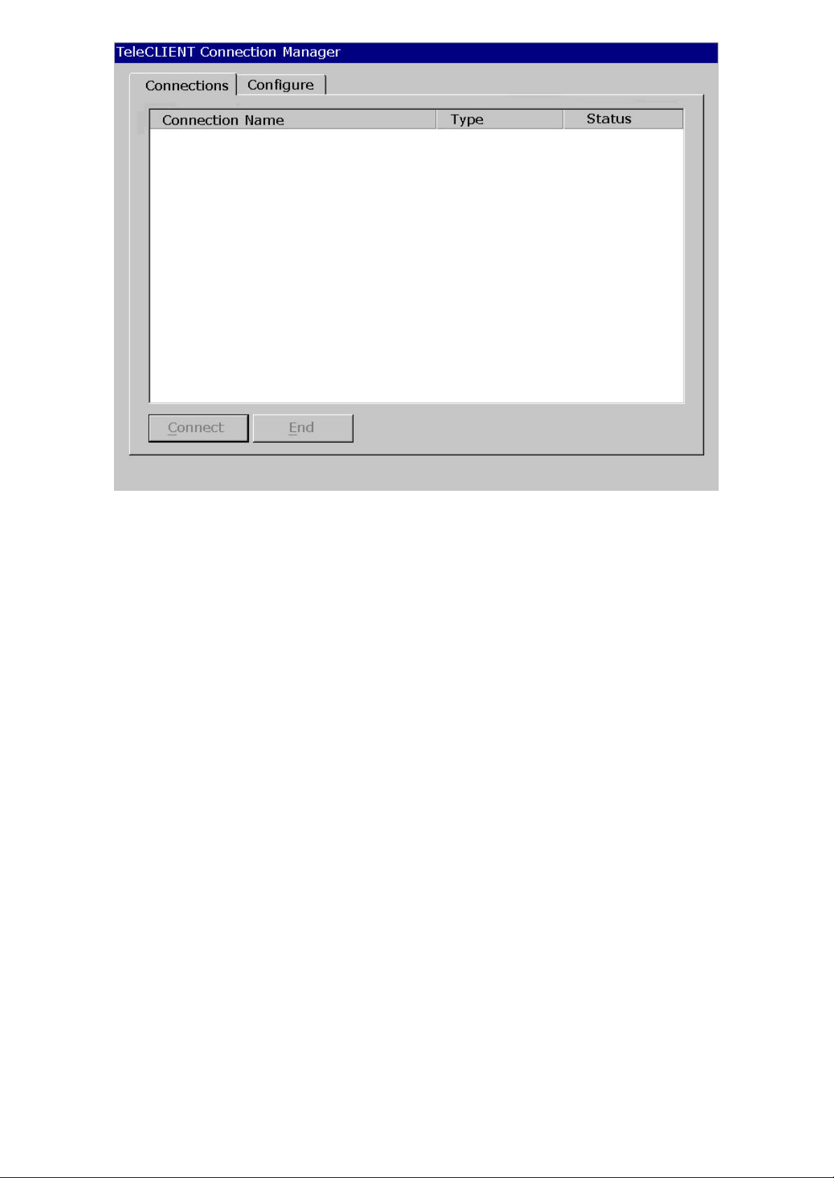
Figure 4-1 TeleCLIENT Connection Manager Window
Notice that the TeleCLIENT Connection Manager window contains two tabs:
76. • Connections - Used to connect TeleCLIENT TC7370 to a network and also end a
network connection
77. • Configure - Used to add, edit and delete network connections. You can also set the
default or auto-start network connection.
52.4.3. Configuring Network Connections
Each connection uniquely identifies a host (server) and the client (terminal) used to make the
connection, based on the type of connection used. You can create, edit and delete network
connections in th e TeleCLIENT Connection Manager window. To begin:
53. 1. Select the Configure tab in the TeleCLIENT Connection Manager window. The
Configure window appears (see Figure 4-2).
-- 4646 / 69 / 69 –
Page 47
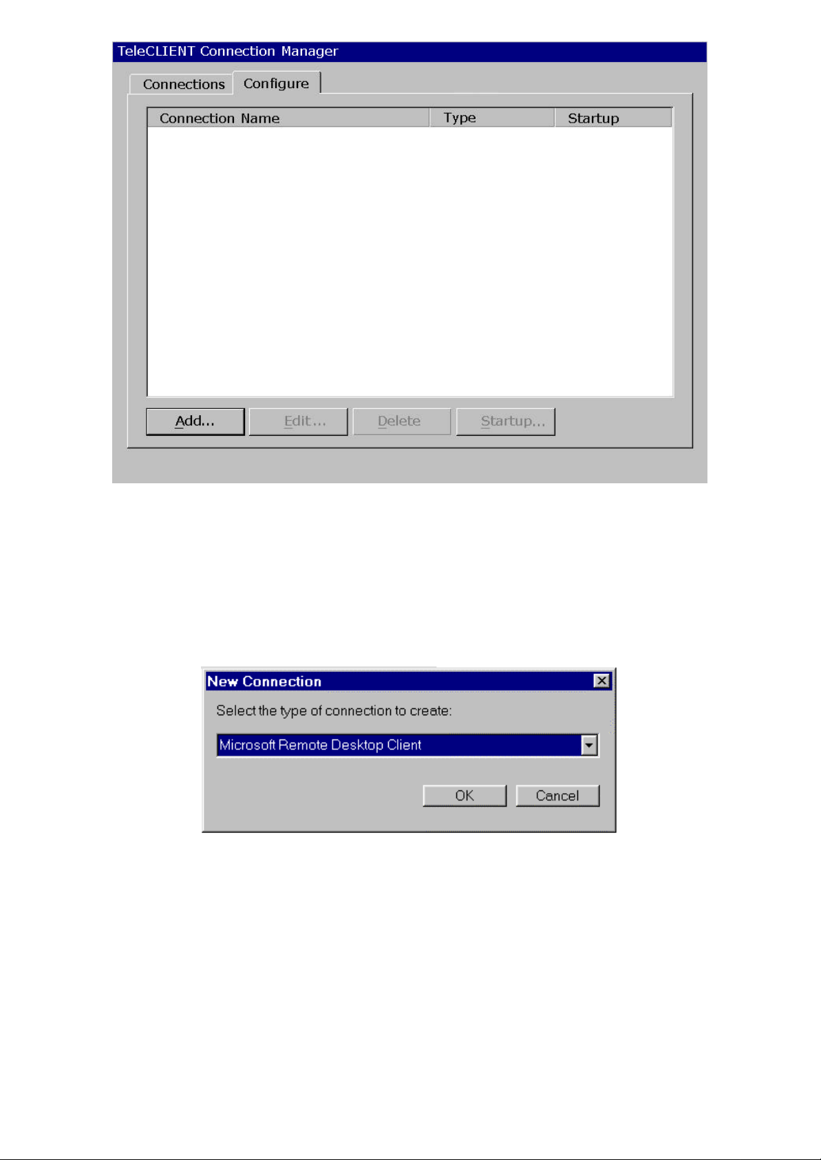
Figure 4-2 Configure Tab Window
54.4.3.1. Creating a New Connection
To create a new connection, complete the following steps:
55. 1. Click Add in the Configure window. The New Connection window appears (see Figure 4-
3).
Figure 4-3 New Connection Window
100. 2. Choose one of the following connection protocols for the new connection:
78. • Citrix Independent Computing Architecture protocol (ICA)
79. • Microsoft Remote Desktop Protocol (RDP)
80. • Terminal Emulation Client
3. Click OKOK. To return to the previous window, click CancelCancel.
Once a connection is created, it will also be listed in the Connection Name list. In Figure 4-4, the active connection is an RDP type.
-- 4747 / 69 / 69 –
Page 48
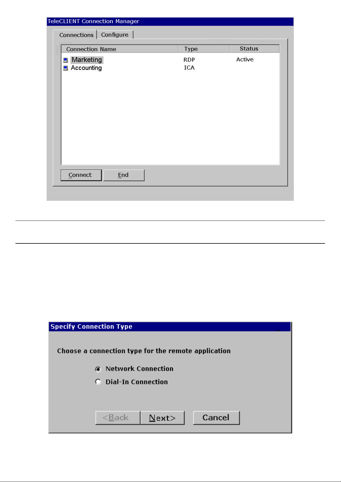
Figure 4-4 Connection Type Defined in TeleCLIENT Connection Manager
NOTE: The remainder of this procedure depends upon the type of connection used as explained
below.
Adding an ICA Client Connection
To add an ICA client connection, complete the following steps:
56. 1. Select ‘Citrix ICA Client’ in the New Connection window. The Specify Connection Type
window appears (see Figure 4-3).
Figure 4-5 Specify Connection Type Window
-- 4848 / 69 / 69 –
Page 49
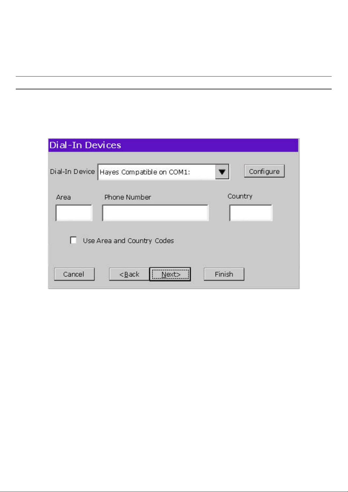
101. 2. Specify the type of connection you wish to make (see figure 4-5):
81. • ‘Network Connection’ - Requires a Ethernet connection.
82. • ‘Dial-in Connection’ - Requires a modem.
102. 3. Click Next.
NOTE: If Network Connection, skip to step 12.
103. 4. If Dial -In Connection enter the area code, phone number, country, and
check the box if you need to dial the area code for the connection (see figure
4-6).
Figure 4-6 Dial-In Device Setting
104. 5. Select the hardware connection from the drop-down box.
105. 6. Click Configure.
106. 7. Under the Port Settings tab, set Manual dialing option and the terminal
screen options (see figure 4-7).
-- 4949 / 69 / 69 –
Page 50
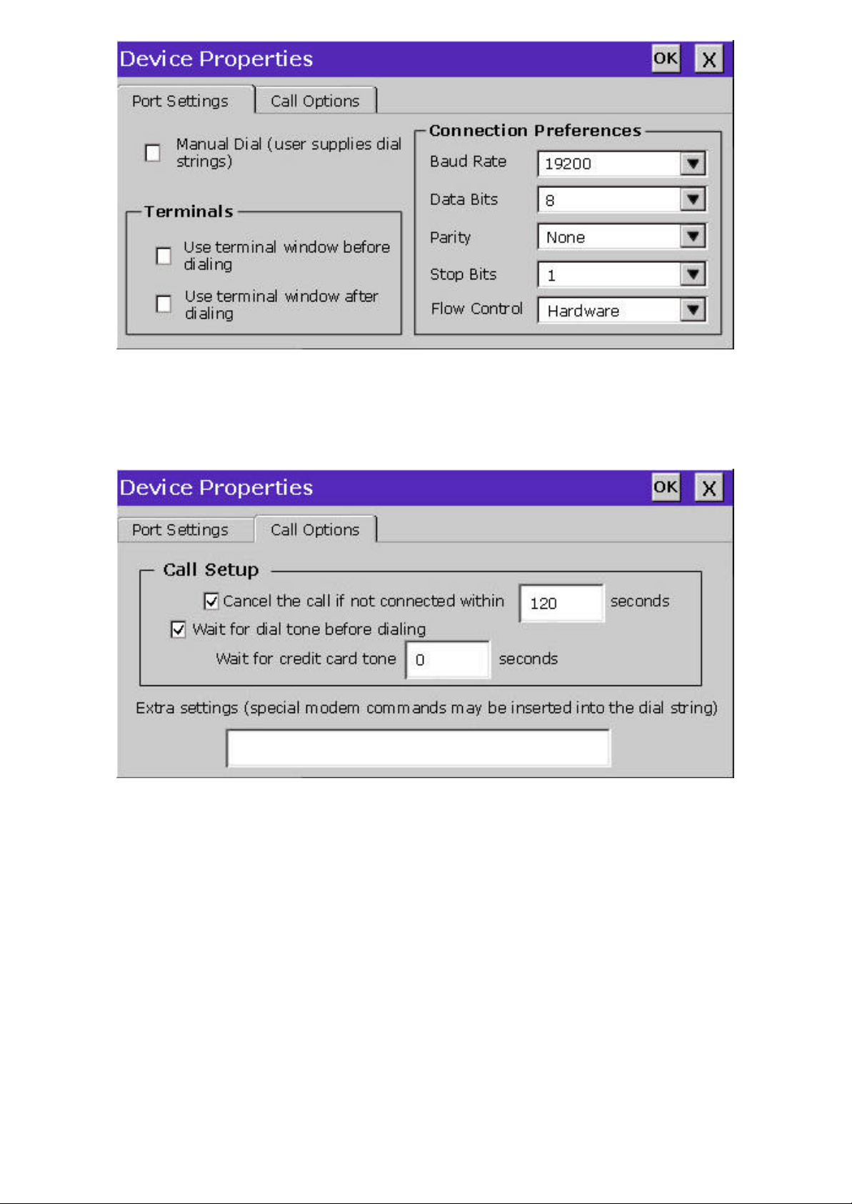
Figure 4-7 Port Settings
107. 8. Set the modem connection by filling in the Connection Preferences boxes.
108. 9. Click on Call Options tab (see figure 4-8).
Figure 4-8 Calling Options
109. 10. Set the calling options then click OK.
110. 11. Click Next.
111. 12. The software will now search for and identify all of the available Citrix
servers or published applications. Follow the prompts to select the server or
application you wish to use (see Figure 4-9).
-- 5050 / 69 / 69 –
Page 51
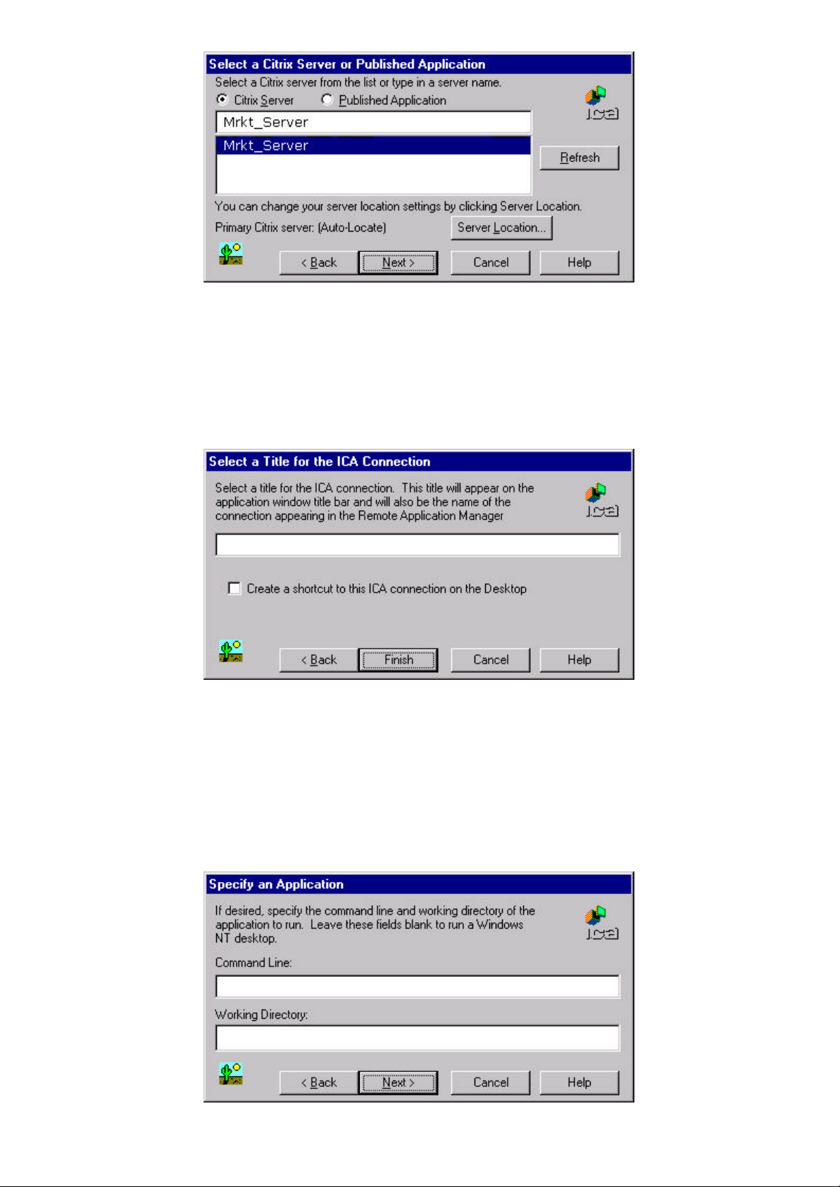
Figure 4-9 Select a Citrix Server or Published Application
112. 13. Click Next.
113. 14. The default server name will appear in the Select a Title for the ICA
Connection window. You can change the title at this time (see Figure 4 -10).
Figure 4-10 Select a Title for the ICA Connection Window
114. 15. Click Next.
115. 16. You can configure your TC7370 to run the same application from the
selected server. Type in the ‘Command Line’ and ‘Working Directory’ or
leave blank to run the Windows NT desktop (see Figure 4-11).
-- 5151 / 69 / 69 –
Page 52
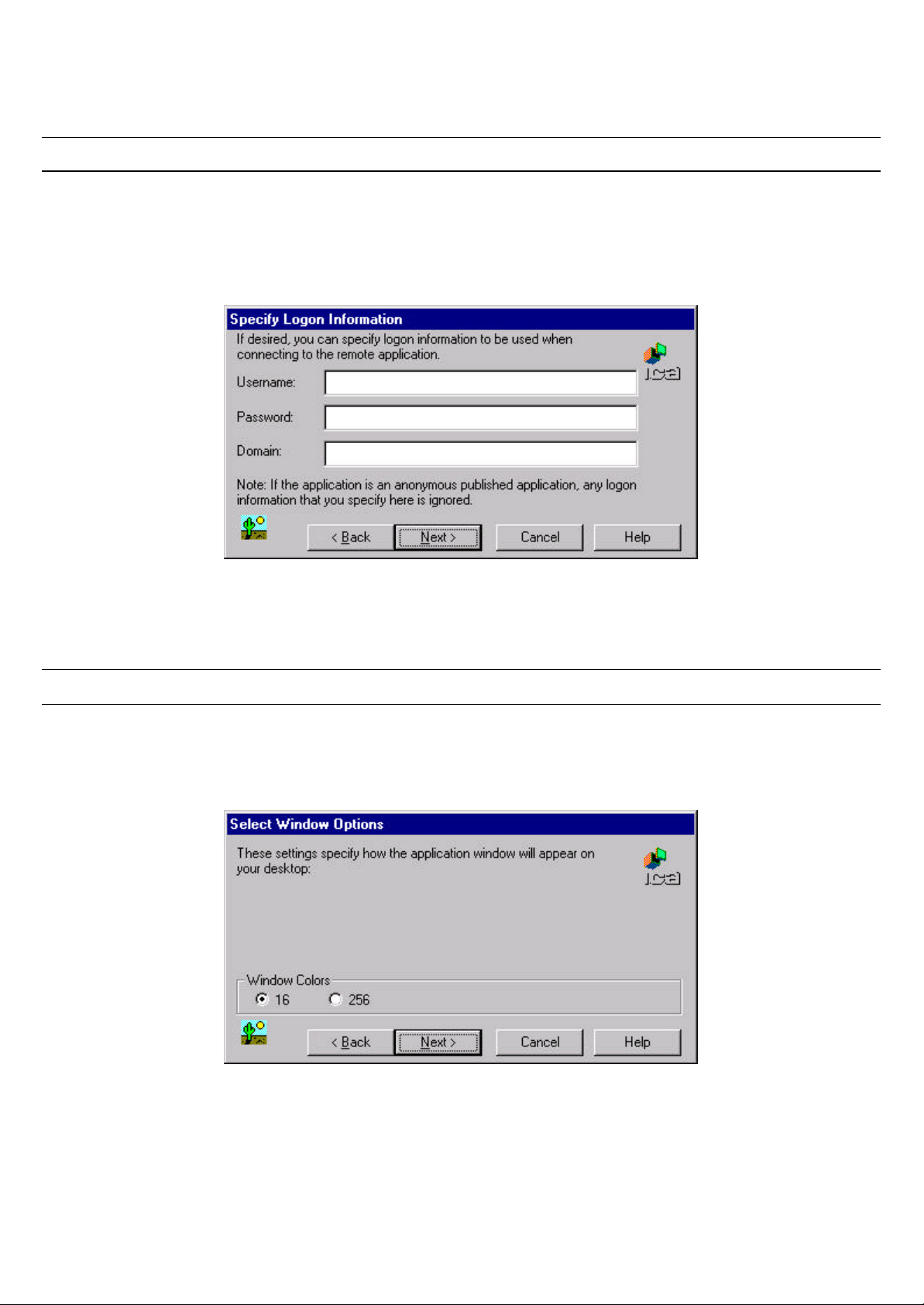
Figure 4-11 Specify an Application Window
116. 17. Click Next.
Note: You may leave this screen blank.
117. 18. You can enter your username, password and domain to log on to the
server. This saves you from logging on each and every time to the server or
application (see Figure 4-12).
Figure 4-12 Specify Logon Information Window
118. 19. Click Next.
Note: You may leave this screen blank.
119. 20. The Select Window Options window allows you to specify 16 or 256 colors
for the ICA session (see Figure 4-13).
Figure 4-13 Select Window Options Window
120. 21. Click Next.
121. 22. The Compression, Cache and Sound window allows you to configure your
ICA session depending on the speed of your connection (see Figure 4-14).
-- 5252 / 69 / 69 –
Page 53

Figure 4-14 Compression, Cache and Sound Window
83. • ‘Compress Data Stream’ – Choose this setting if you are connected via a modem
dial-up or a Wide Area Network (WAN).
84. • ‘Cache’ – Under all ICA sessions, caching is enabled. Therefore, this setting cannot
be changed.
85. • ‘Enable Sound’ – Choose this setting if you have a Local Area Connection, i.e.
10/100BaseT. Enabling sound over a modem dial-up or a WAN will cause problems due
to an increased consumption of bandwidth.
122. 23. Click Next (or click Finish if you do not have to set up the firewall settings
and skip the following procedure. You are ready for the connection).
123. 24. Once you have finished the ICA connection setup, you are now ready to
connect to the server.
Adding an RDP Client Connection
57. 1. Select ‘Microsoft Remote Desktop Client’ in the New Connection window. The
Windows Terminal Server (WTS) Connection Wizard window appears (see Figure 4-15).
-- 5353 / 69 / 69 –
Page 54
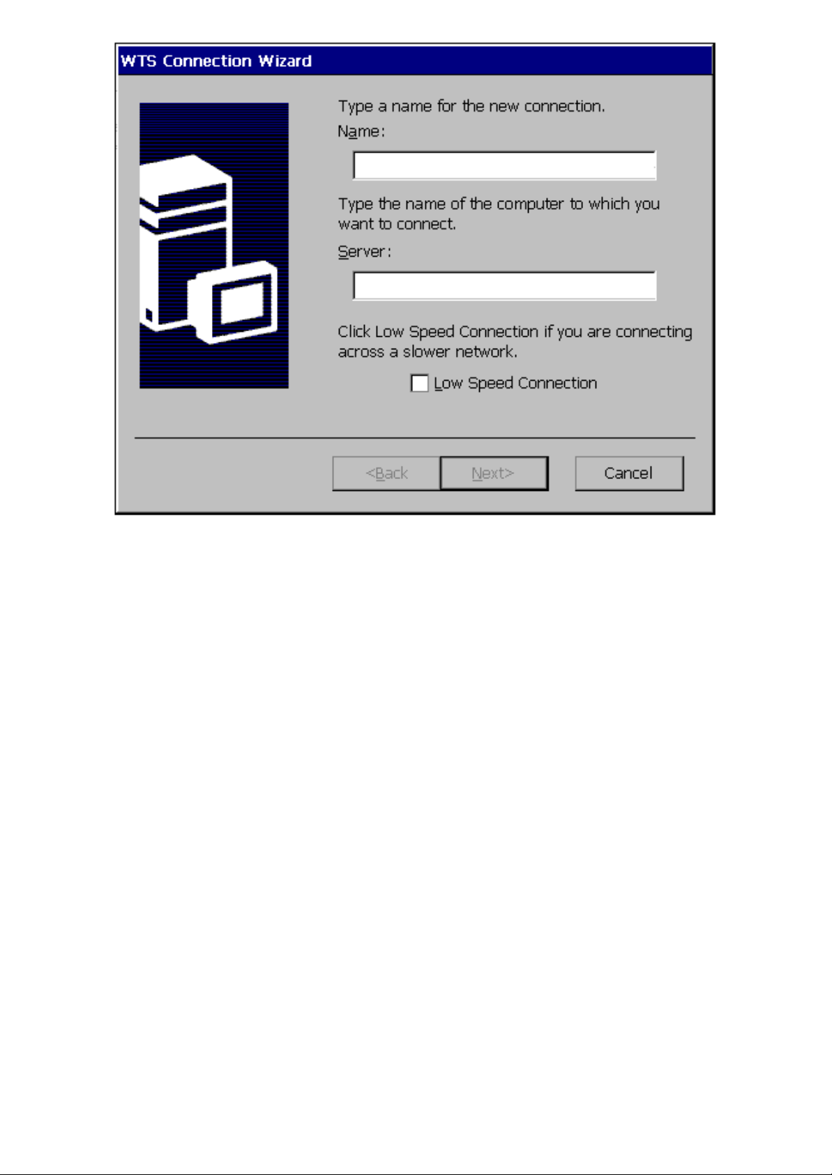
Figure 4-15 WTS Connection Wizard Window
124. 2. Enter a name for the new connection in the ‘Name’ field.
125. 3. Enter the server name or IP address of the computer you wish to connect
to in the ‘Server’ field.
126. 4. If you have a connection to the Server through a low bandwidth line (WAN
or serial line), check Low Speed Connection.
127. 5. Click Next.
128. 6. You can enter your username, password and domain to log on to the
server. This saves you from logging on each and every time to the server or
application (see Figure 4-16).
-- 5454 / 69 / 69 –
Page 55
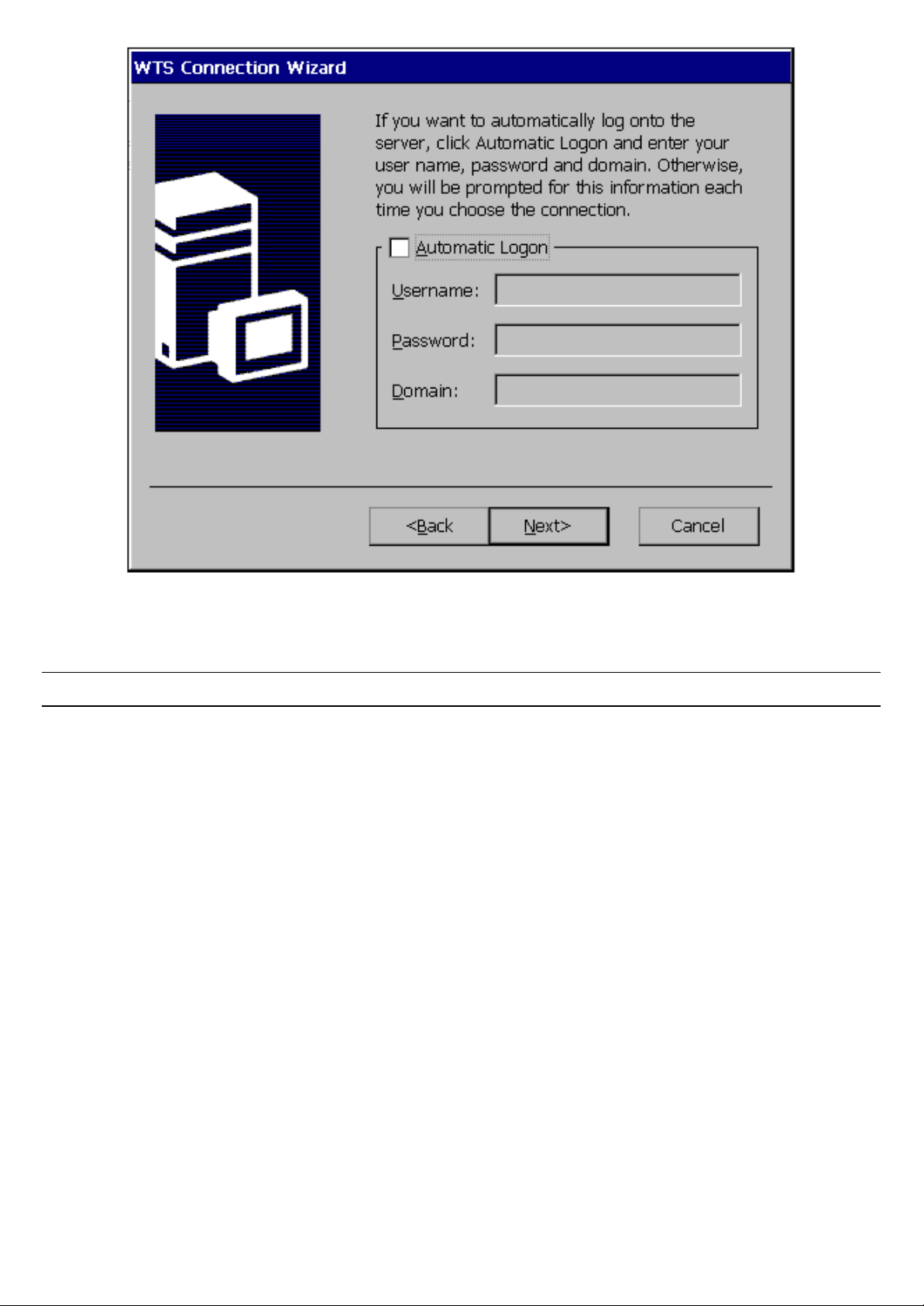
Figure 4-16 WTS Connection Wizard Window
129. 7. Click Next.
Note: You may leave this screen blank.
130. 8. You can configure your TC7370 to run a selected application, instead of
the desktop. Choose the ‘Application File Name’. Type in the ‘Command
Line’ and ‘Working Directory’, or leave blank to run the Windows NT desktop
(see Figure 4-17).
-- 5555 / 69 / 69 –
Page 56
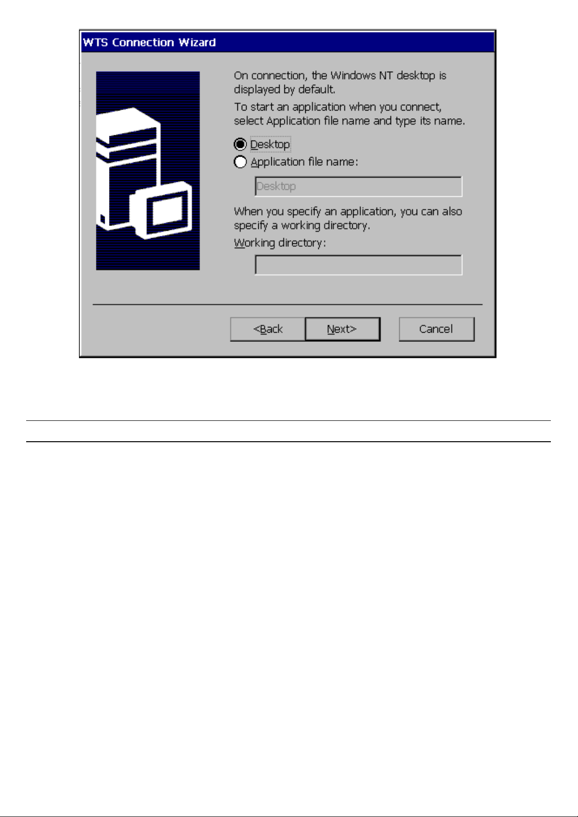
Figure 4-17 WTS Connection Wizard Window
131. 9. Click Next.
Note: You may leave this screen blank.
132. 10. Congratulations! You have successfully created a connection to the
server (see Figure 4-18).
-- 5656 / 69 / 69 –
Page 57
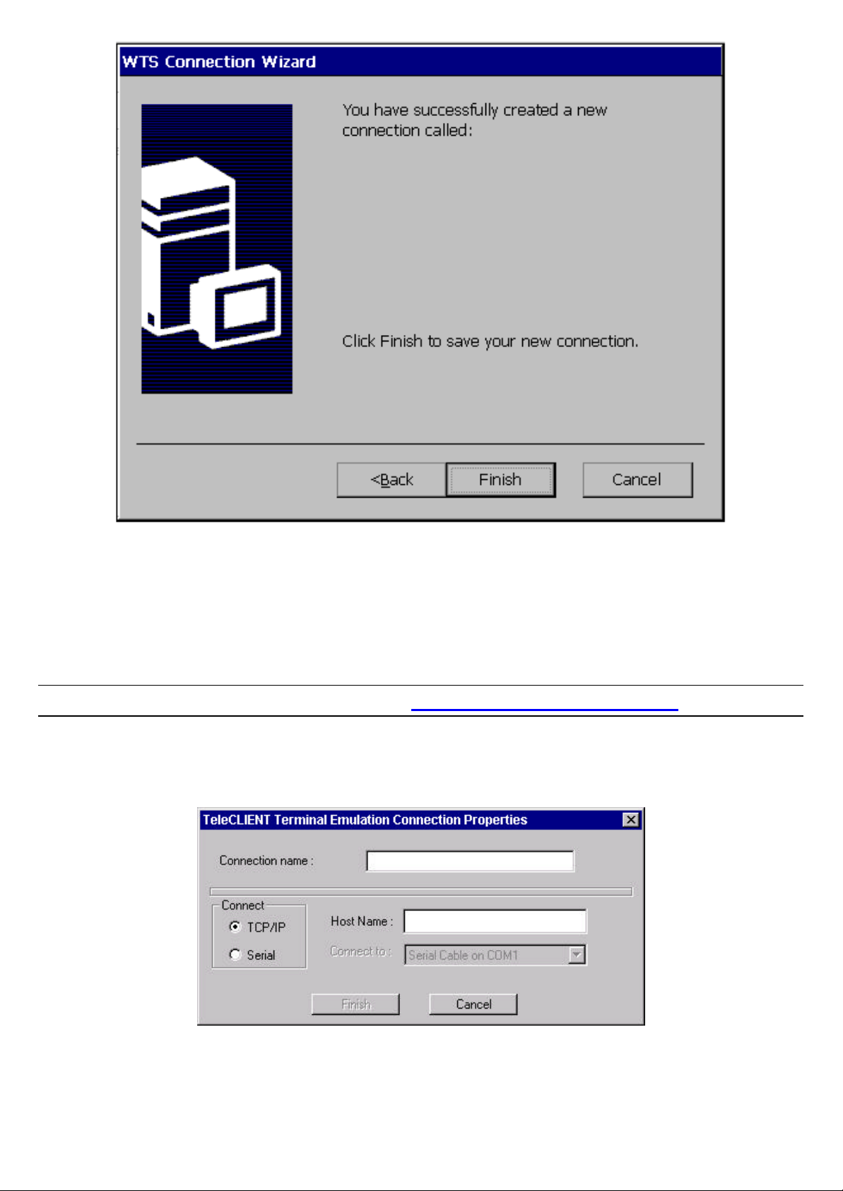
Figure 4-18 WTS Connection Wizard Window
133. 11. You have completed adding a Microsoft RDP client. Click Finish.
Once you have finished the WTS Connection Wizard setup, you are now ready to connect to the server.
Adding a Terminal Emulation Client Connection
Note: For more information, please refer to - Terminal Emulation User’s Guide
58. 1. Select ‘Terminal Emulation Client’ in the New Connection window. The TeleCLIENT
Terminal Emulation Connection Properties window appears (see Figure 4-19).
Figure 4-19 Terminal Emulation Connection Properties Window
134. 2. Enter a name in the ‘Connection Name’ field.
-- 5757 / 69 / 69 –
Page 58
135. 3. Select the desired connection type, either TCP/IP or Serial.
86. • If you selected TCP/IP, enter IP address of the host computer (server) in the Host
Name field.
87. • If you selected Serial, select the serial port, either COM1 or COM2 for your
connection.
136. 4. Click Finish.
Once you have finished the TeleCLIENT Terminal Emulation setup, you are now ready to connect to the server.
59.4.3.2. Editing Connections
The procedure for editing a connection varies, depending on the kind of network connection you use.
Editing an ICA Connection
To edit an ICA connection, complete the following steps:
60. 1. Select the Configure tab in the TeleCLIENT Connection Manager window (see Figure
4-20).
137. 2. Select the connection you wish to edit from the ‘Connection Name’ list.
138. 3. Click Edit.
139. 4. Follow the prompts to select a Citrix Server or Published Application.
Editing an RDP Connection
Figure 4-20 Configure Tab
-- 5858 / 69 / 69 –
Page 59
61. 1. Select the Configure tab in the TeleCLIENT Connection Manager window.
140. 2. Select the RDP connect ion you wish to edit from the ‘Connection Name’
list.
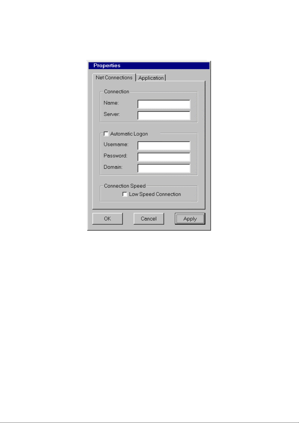
141. 3. Click Edit. The Properties window appears (see Figure 4-21).
Figure 4-21 Properties Window
Notice that the Properties window contains two tabs:
88. • Net Connections – Used to edit a connection and enable an automatic logon (see
Figure 4-18).
89. • Application – Used to specify and automatically go to the filename and working
directory path whenever you start a session (see Figure 4-22).
-- 5959 / 69 / 69 –
Page 60
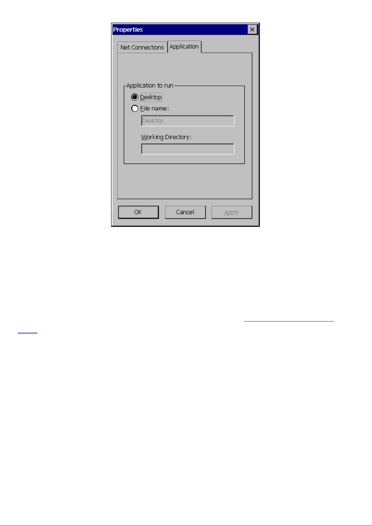
Figure 4-22 Properties Window - Application Tab
142. 4. Make the necessary changes in the ‘Net Connections’ or ‘Application’.
143. 5. Click Apply.
144. 6. When finished, click OK.
Editing a Terminal Emulation Connection
Please refer to Adding a Terminal Emulation Client section or the Terminal Emulation User’s
Guide.
62.4.3.3. Deleting a Connection
63. 1. Select the Configure tab in the TeleCLIENT Connection Manager window.
145. 2. Select the connection you wish to delete by clicking on connection name.
146. 3. Click Delete.
147. 4. Click Yes to confirm the deletion.
64.4.3.4. Setting Start -up Connections
The TeleCLIENT TC7370 can be set to automatically connect to a server whenever a session begins
instead of using the default server.
To set automatic start -up connections, complete the following steps:
65. 1. Select the Configure tab in the TeleCLIENT Connection Manager window.
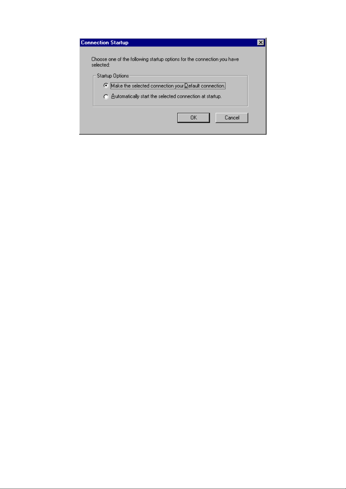
148. 2. Click Startup. The Connection Startup window appears (see Figure 4-
-- 6060 / 69 / 69 –
Page 61
23).
Figure 4-23 Connection Startup Window
149. 3. Select one of the following Startup Options:
90. • Make the selected connection your default connection – Enables the default
connection selected in the TeleCLIENT Connection Manager. The default connection is
the one highlighted when TeleCLIENT TC7370 powers on and TeleCLIENT Connection
Manager window appears.
91. • Automatically start the selected connection at startup – Enables the TeleCLIENT
TC7370 to automatically connect to your selection in the TeleCLIENT Connection
Manager each time a user starts up TeleCLIENT TC7370.
150. 4. Click OK to save your changes.
66.4.4. Connecting to a Network Server
The TeleCLIENT Connection ManagerTeleCLIENT Connection Manager lists all of your system’s available network connections.
To connect to a server, complete the following steps:
Click the ConnectionsConnections tab in the TeleCLIENT Connection ManagerTeleCLIENT Connection Manager window (see Figure 4-24).
-- 6161 / 69 / 69 –
Page 62
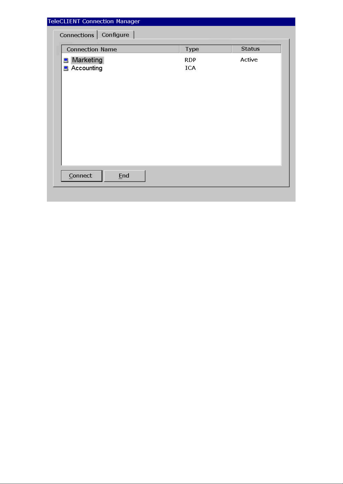
Figure 4-24 TeleCLIENT Connection Manager Window
67. 1. Select a Connection Name in the connection list.
151. 2. Click Connect (or double-click on the Connection Name). If the
connection was defined for automatic logon and the server it connects to is
enabled, the TeleCLIENT TC7370 makes the connection and the user is
automatically logged on.
152. 3. If the logon is not automatic, the Windows Logon Information window
displays. Follow the Windows prompts to complete the logon.
68.4.5. Using the TeleCLIENT TC7370 Hot Keys
The TeleCLIENT TC7370 hot keys simplify the process of switching between active sessions.
Instead of using the TeleCLIENT Connection Manager, you can use the hot keys on your
TeleCLIENT TC7370 keyboard to automatically switch between sessions in a single step.
There are several available TeleCLIENT hot keys, described in
Table 4-1.
-- 6262 / 69 / 69 –
Page 63

Toggles directly to the TeleCLIENT Connection
When the TeleCLIENT Connection Manager is active,
toggles directly to the TeleCLIENT Terminal Properties
Table 4-1. TeleCLIENT TC7370 Hot Keys
Hot Key Function
CTRL+ALT+up arrow Toggles up between active sessions.
CTRL+ALT+down arrow Toggles down between active sessions.
CTRL+ALT+HOME Automatically toggles to the default session.
CTRL+ALT+END
<F2>
If hot keys are not enabled, fo llow the instructions in Section 4.5.1, Starting Multiple ConnectionsStarting Multiple Connections to switch between active connections.
Manager.
window.
69.4.5.1. Starting Multiple Connections
The TeleCLIENT TC7370 allows multiple simultaneous connections. The number of connections
started is limited by the amount of RAM available in the TeleCLIENT TC7370.
To start a second connection, complete the following steps:
70. 1. Press CTRL+ALT+END on the keyboard to access the TeleCLIENT Connection Manager.
153. 2. Select the Connection Name. Click Connect.
To switch between running connections, complete the following steps:
71. 1. Press CTRL+ALT+END on the keyboard to access the TeleCLIENT Connection Manager.
154. 2. Select a Connection Name. Click Connect.
155. 3. OR, on the keyboard, press CTRL+ALT+UP (with the up arrow) or
CTRL+ALT+DOWN (with the down arrow) to cycle through the list of active
connections. The Connection list reflects the order in which the connections
were started, with the most recent at the top of the list.
72.4.6. Logging Off
To log off and end a session:
When connected to an application, close the application to terminate the connection.
When connected to a server’s desktop, complete the following steps:
73. 1. Close all applications.
156. 2. Click Start on the taskbar at the bottom of the Windows Terminal Server
(WTS) desktop.
157. 3. Select Logoff.
158. 4. Click OK in the panel that displays. WTS closes any programs that are
still running.
A new session will now start, or the TeleCLIENT Connection ManagerTeleCLIENT Connection Manager window will appear. The TeleCLIENT TC7370 may now be
powered off.
-- 6363 / 69 / 69 –
Page 64

74.4.6.1. Ending Auto- Start Connections
To end an auto-start connection, complete the following steps:
75. 1. Press CTRL+ALT+END on the keyboard to access the TeleCLIENT Connection Manager.
159. 2. Select the Configure tab.
160. 3. Select the auto-start Connection Name and click Startup. The
TeleCLIENT Connection Startup window appears.
161. 4. Click on the ‘Make the selected’ connection your Default connection.
Click OK.
162. 5. Select the connection and click End.
-- 6464 / 69 / 69 –
Page 65

Appendix A
76. 5. Specifications
This chapter contains the following TeleCLIENT TC7370 specifications:
92. • Hardware Specifications
93. • Networking and Communications
94. • Software Specifications
95. • Environmental
96. • Regulatory Compliance
97. • Physical Characteristics
98. • Warranty Information
Table A-1 provides the TeleCLIENT TC7370 hardware specifications.
Figure 3-1 Table A-1 TeleCLIENT TC7370 Hardware Specifications
HardwareHardware DescriptionDescription
CPU
§ National Semiconductor Geode
GX1™ 300MHz processor
RAM Memory
§ 32MB RAM standard
§ Expandable to 128MB
Flash Memory
§ 8MB flash disk
§ Flash upgrade utility via Ethernet
Graphics Subsystem
§ National Semiconductor
XpressGRAPHICS™, Cx5530
Video Memory
Audio Support
§ Graphics utilizes system RAM
§ National Semiconductor
XpressAUDIO™
§ Full 16-bit stereo FM synthesis
§ Audio Out –Microphone in
Resolution
§ Resolution of 1024x768
§ 16 to 65K colors
§ Supports all VESA monitors
Table A-2 provides the Networking, Communications and Input/Output specifications.
-- 6565 / 69 / 69 –
Page 66

Figure 3-2 Table A-2 Networking, Communications and Input/Output Specification s
ItemItem DescriptionDescription
Networking Protocols
§ 10/100BaseT Ethernet, RJ45
§ TCP/IP with DNS, DHCP and
PPP
§ Load balancing supported by
Citrix ICA
§ Remote modem dial up with Citrix
ICA
Communication Protocols
§ Microsoft RDP
§ Citrix ICA
Parallel Port
USB Ports
Audio Ports
§ One parallel port
§ Two USB ports
§ Audio out
§ Microphone in
Keyboard and Mouse Ports
§ Keyboard and mouse ports (PS/2
keyboard and mouse included)
Table A-3 provides the TeleCLIENT TC7370 software specifications.
Figure 3-3 Table A-3 Software Specifications
FeatureFeature DescriptionDescription
Operating System
Set-up and Configuration
Remote Management Software
§ Microsoft Windows CE
§ TeleManager Management
Software compatible
§ TeleCLIENT Setup Wizard for
fast, simple connection to the
network
§ Login configured for server
access
§ Familiar Windows graphical user
interface
§ Local power -on
§ TeleManager Management
Software
-- 6666 / 69 / 69 –
Page 67

Server Operating System Support*
§ Microsoft Windows NT Server 4.0,
Terminal Server Edition
§ Microsoft Windows 2000 Terminal
Services
§ Citrix WinFrame
§ Citrix MetaFrame
ASCII Terminal Emulation Support*
§ TeleVideo 925
§ Wyse 60/50+/50
§ ADDS VP/A2
§ UNIX console
ANSI Terminal Emulation Support*
§ DEC 420/320/220/100/52
§ SCO Console
IBM Mainframe*
IBM Midrange AS400*
* Terminal emulation support optional. Additional emulations available by request only. Please contact TeleVideo directly for further
§ IBM 3287/3270E/3270
§ IBM 5250
information.
Table A-4 provides the environmental specifications.
Figure 3-4 Table A-4 Environmental Specifications
FeatureFeature DescriptionDescription
Environmental Specifications
Power Specifications
§ Operating temperature 32º to
104ºF (0º to 40ºC)
§ Storage temperature -14º to
140ºF (-25º to 60ºC)
§ State-of-the art, fanless
convection cooling design
§ Humidity 10% to 85%, noncondensing
§ Operating altitude of 0 to 10,000
feet (3050 meters)
§ External power supply
Table A-5 provides the regulatory compliance specification s.
Figure 3-5 Table A-5 Regulatory Compliance Specifications
FeatureFeature DescriptionDescription
§ 100-240 VAC at 50-60Hz
§ 4.58A
§ 55W nominal
-- 6767 / 69 / 69 –
Page 68

Regulations
Table A-6 provides the physical specifications.
Figure 3-6 Table A-6 Physical Specifications
FeatureFeature DescriptionDescription
§ EPA ENERGY STAR®
§ FCC Class B
§ CE Mark
Weight
Height
Depth
Width
§ 10.5 lbs
§ 15.1 inches
§ 7.2 inches
§ 15.7 inches
Warranty Information
The TeleCLIENT TC7370 is supported by a one-year warranty service. Please contact your TeleVideo, Inc. representative for more
information.
-- 6868 / 69 / 69 –
 Loading...