

Page 1

V1.0 2009.04.02
RemoDAQ-8554A GPRS DTU
User’s Manual
Beijing Gemotech Intelligent Technology Co.,Ltd
Page 2

Table of Contents
Chapter 1 Introduction...................................................................................................................3
1.1 Brief Introduction.............................................................................................................3
1.1.1 Measurement.........................................................................................................4
1.1.2 Open Box ..............................................................................................................4
1.1.3 Constitutive...........................................................................................................5
1.1.4 Specifications........................................................................................................5
1.2 Function Features.............................................................................................................6
1.3 Installation........................................................................................................................7
1.3.1 SIM Card Installation............................................................................................7
1.3.2 User Data and Power Cable Installation................................................................7
1.3.3 Grounding ...........................................................................................................10
1.3.4 Power Supply......................................................................................................10
Chapter 2 DTU Setup...................................................................................................................12
2.1 Setup Connection...........................................................................................................12
2.2 Parameters Configuration...............................................................................................12
2.3 Parameters Explanation..................................................................................................14
2.3.1 Mobile Service Center Setup...............................................................................14
2.3.2 Data Terminal Unit Setup....................................................................................15
2.3.3 Data Service Center Setup...................................................................................16
2.3.4 Serial Port Setup..................................................................................................16
2.3.5 Special Setup.......................................................................................................17
Chapter 3 Operation.....................................................................................................................19
3.1 Panel Indications............................................................................................................19
3.2 DTU Operation Guidance ..............................................................................................19
3.3 Trouble Shooting............................................................................................................20
Appendix Debug Case .................................................................................................................21
Page 3
Chapter 1 Introduction
This chapter introduces RemoDAQ-8554A GPRS DTU descriptions, features and
installation.
1 Brief Introduction
2 Function Features
3 Installation
1.1 Brief Introduction
Based on years of experience of providing mobile data’s industrial application
solutions and service operator’s network configurations, BeiJing GemoTech has
designed RemoDAQ-8554A GPRS DTU which works at an adv anced platf orm with
individualized feature options to meet different requirements. Along with mobile
communication technology’s development, t he GPRS data networks have co vered
all country; this brings a bright future for industrial applications.
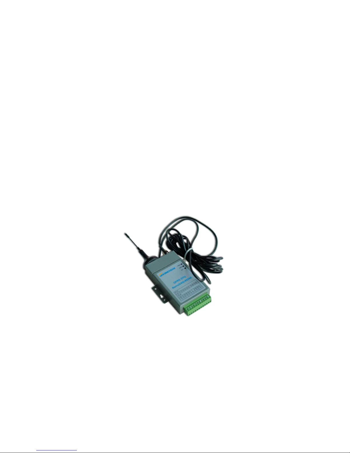
Figure1.1 RemoDAQ-8554A GPRS DTU
GPRS network theoretically can provide a maximum bandwidth 171.2Kbps,
actually, it works at 40~100Kbps bandwidth (it depends on service provider’s
operation policy). As we know, GPRS is packet based network which provides
TCP/IP communication channel.
RemoDAQ-8554A GPRS DTU provides industrial end-user a virtual private data
network of high speed, always online, and transparent data transmission. It can
be widely used at area power system, industrial supervision, automatic traffic
control, weather station, environment protection, pipe supervision, finance and
Page 4
securities, etc.
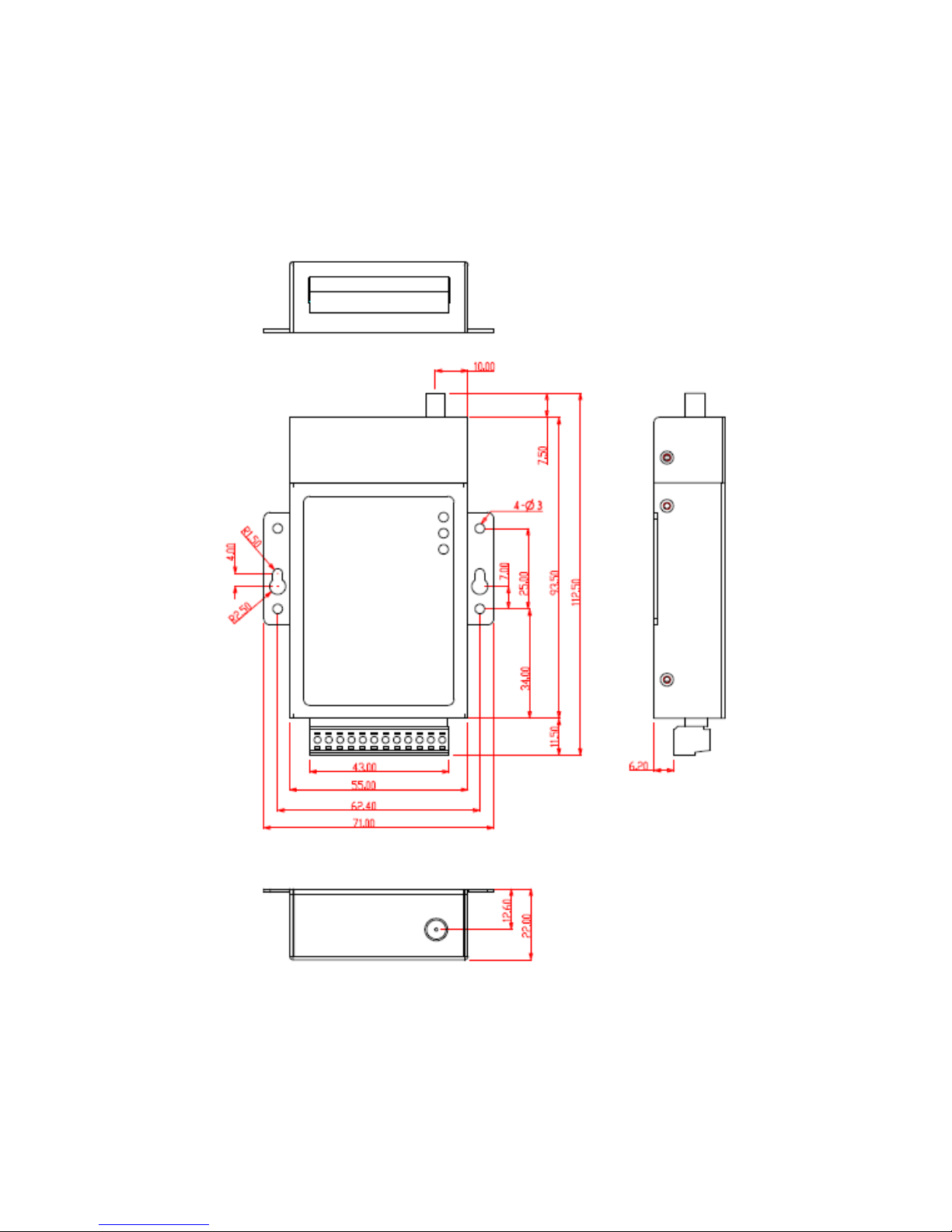
1.1.1 Measurement
RemoDAQ-8554A GPRS DTU outside measurement and installation position:
Figure1.2 product shape size
1.1.2 Open Box
In order to protect products during shipment, RemoDAQ-8554A GPRS DTU has
Page 5

been packed properly. Y ou may need to keep the packing materials f or reshipping
after you open the pack box.
RemoDAQ-8554A GPRS DTU package includes:
RemoDAQ-8554A GPRS DTU 1 piece
User Manual 1 copy (CD-ROM)
Qualified & Repair Card 1 piece
Test Cable 1 piece
Optional Accessories:
Standard Antenna
Vehicle Antenna
Directional Antenna
After you open the box, you should count it carefully with your purchase order.
1.1.3 Constitutive
32bits Philips MPU
GPRS Module SIM300C
1.1.4 Specifications
RemoDAQ-8554A GPRS DTU’s main specifications:
GPRS Data
GPRS Class 10
Coding Scheme: CS1 - CS4
Complies SMG31bis Specifications
Interface
Antenna 50/SMA/Female
SIM 3V
Serial Port
Interface RS-232/RS-485
Data Rate 300~115,200bits/s
Terminal 3.5mm Pluggable Terminal, 12pin
Page 6

Power
Voltage +12~30VDC
Ripple <300mV
Consumption
Idle Current 30mA@+12VDC
Work Current 50~140mA@+12VDC
Others
Measurement 112.5x70x22 (Not include antenna, installation pack and
connector)
Weight 160g
Work Temperature -20~+55C
Store Temperature -25~+70C
Relative Humidity 95%(non-condensing)
1.2 Function Features
z Support RS-232/RS-485 data interface
z Using conveniently, flexibly, reliably
z Data terminal always online, support data service center dynamic IP address
and domain name
z Transparent data transmission and protocol conversion, operation mode
selection
z Software / hardware watchdog, EMC/EMI design
z Support UGI based remote configuration and maintenance, integrated with
data service center
z System maintenance and configuration interface
z Support SMS Channel
z Support the virtual private data network
z Power management for wide range power input
z Industrial class pluggable terminal for signal connections designed with
customer specified options
Page 7

1.3 Installation
RemoDAQ-8554A GPRS DTU should be installed and configured properly before
putting it in service.
Attention:
Do not install RemoDAQ-8554A GPRS D TU or connect/disconnect its cable when it
is power on.
1.3.1 SIM Card Installation
Open top SIM protection cover, and then insert SIM from left-top side. SIM card
conductors should face downside and the gap face to outside. The SIM card also
need to be inserted properly and then cove back the SIM protection cover in order
to prevent the SIM card from dropping out during shipping. Slide the SIM card by
your finger to ta ke out the SIM card.
Attention:
RemoDAQ-8554A GPRS D TU will not work and displa y “No SIM card, Please insert
SIM!” if you do not insert the SIM car d to the end position. In order to prevent this
problem, please put back the SIM cove r after you insert the SIM card, and scre w
it tight.
1.3.2 User Data and Power Cable Installation
RemoDAQ-8554A GPRS DTU signals and power supply is connected by industrial
class pluggable terminals, 3.5mm, 12Pin, and 14~24AWG outlet cable is
recommended. Each line definition refers to the following diagrams and tables.
Also, you can find outlet cable def inition table at top of RemoDAQ-8554A GPRS
DTU cover.
As shown in the following diagrams and tables, peel off the cable end about 7mm
and connect each terminal and cable (14~24AWG cable recommended). Make
sure that you have connected the terminals without any mistake.
Attention:
1. The power cable should be connected correctly. We suggest double check
before switch it on. Wrong connections may destroy the equipment.
2. Power terminals: Pin 11 and Pin 12; Here: Pin 11 is “GND”, Pin 12 is power
input “Vin+” (+12~+30VDC).
RemoDAQ-8554A GPRS DTU RS-232 interface and power supply illustration:
Page 8
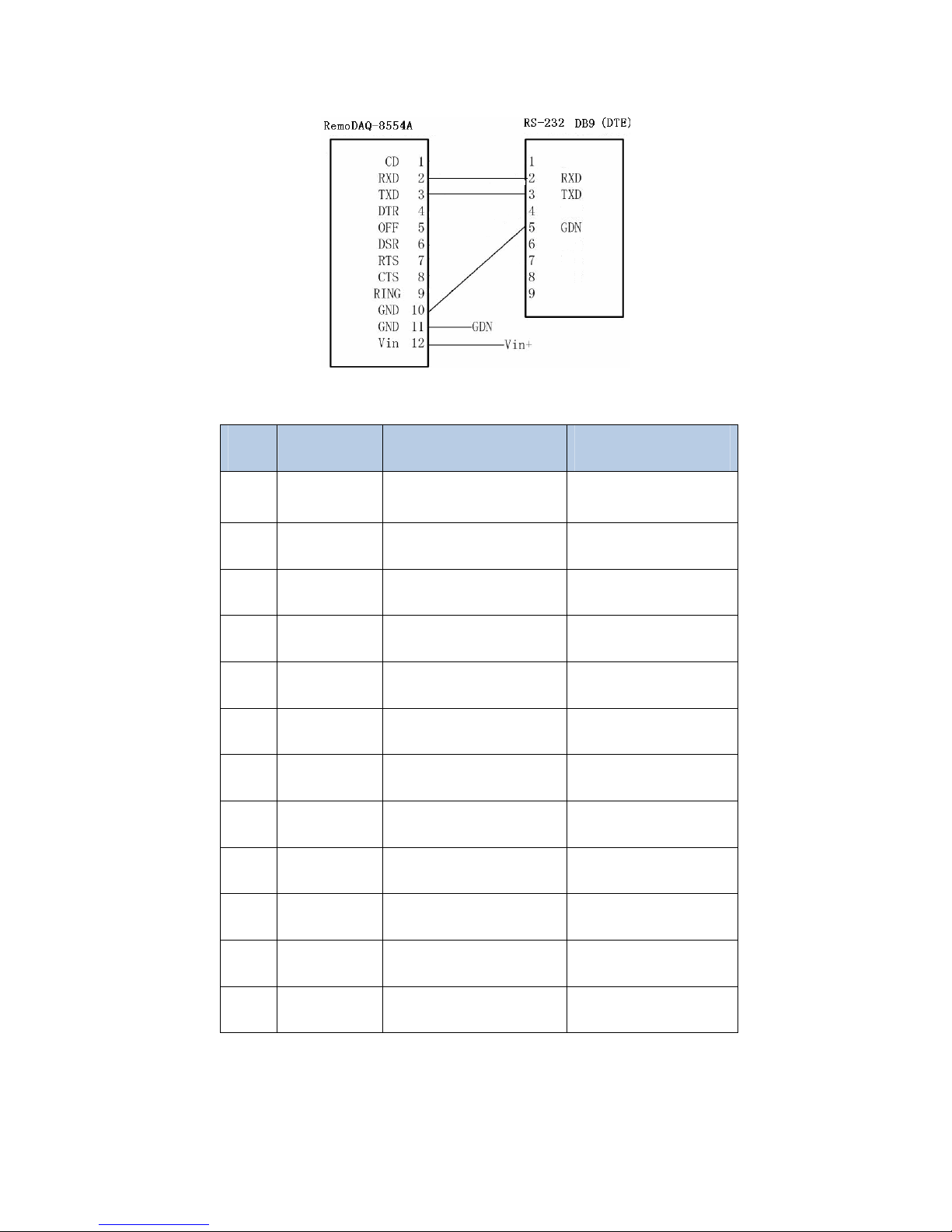
RS-232 signal definition
Pin Signal Description Note
1 DCD Carrier Detection Function reserved
2 RXD Receive Data
3 TXD Transmit Data
4 DSR Data Set Ready Function reserved
5 OFF DTU Power Control Function reserved
6 DTR Data Terminal Ready Function reserved
7 CTS Clear to Send Function reserved
8 RTS Request to Send Function reserved
9 RING Ring Indicator Function reserved
10 GND System Ground
11 GND Power “-”
12 VIN Power “+“
Before using RS-485 interface, please adjust 8 bits DIP Switch which is inside the
DTU. The number 1,2,3,4 are at OFF, and the number 5,6,7,8 are at ON.
RS-232/RS-485 the status of DIP Switch
Page 9

1 2 3 4 5 6 7 8
RS-232 ON ON ON ON OFF OFF OFF OFF
RS-485 OFF OFF OFF OFF ON ON ON ON
RemoDAQ-8554A GPRS DTU RS-485 interface and power supply illustration:
RS-485 signal definition
Pin Signal Description Note
1 GPIO(DCD)
General Purpose Input
Output
Function reserved
2 485-B(-) 485-B(-)
3 485-A(+) 485-A(+)
Page 10

4 GPIO
General Purpose Input
Output
Function reserved
5 PWRCON DTU Power Control Function reserved
6 GPIO
General Purpose Input
Output
Function reserved
7 GPIO
General Purpose Input
Output
Function reserved
8 GPIO
General Purpose Input
Output
Function reserved
9 GPIO
General Purpose Input
Output
Function reserved
10 GND System Ground
11 GND Power “-”
12 VIN Power “+“
1.3.3 Grounding
To ensure a safe, stable and reliable R emoDAQ-8554A GPRS D TU oper ation, D TU
cabinet should be grounded properly. Connect the RemoDAQ-8554A GPRS DTU
cabinet to site ground wire at the ground point
1.3.4 Power Supply
RemoDAQ-8554A GPRS DTU is designed with advanced power management
technologies; it can operate standalone. The DC power is supplied via pluggable
terminal Pin 11 (GND) and Pin 12 (Vin).
About Power Supply
When RemoDAQ-8554A GPRS DTU communicates with base station, surge
current will exceed normal current. Therefore, margins 5 times over normal
current may be required for external power supply.
Normally, RemoDAQ-8554A GPRS DTU input power supply is +12~+30VDC, in
Page 11

most cases, 12VDC/1A is recommended. Power input of +5VDC can be ordered
for specified application. Power supply ripple should be less 300 mV.
Page 12

Chapter 2 DTU Setup
This chapter introduces the RemoDAQ-8554A GPRS DTU parameters
configuration before putting it in service.
1 Setup Connection
2 Parameters Configuration
3 Parameters Explanation
RemoDAQ-8554A GPRS DTU is built-in with a set of DTU Management Tools for
DTU configuration, management and commissioning. Use the tools to configure
DTU parameters before putting it in service and change the configurations during
system commissioning. The tools can also be used to upgrade the DTU software.
2.1 Setup Connection
RemoDAQ-8554A GPRS DTU should be configured properly before putting into
service. You can configure and manage DTU parameters by connecting DTU to
your PC via a configuration cable. Also, it is possible to access the management
tools via the user data interface. The below paragraphs are described at user data
interface configuration.
Serial Port
DTU Configuration Cable Connection
2.2 Parameters Configuration
Page 13

Run “GPRS DTU parameters configuration” software:
Select correct COM, then click “Open COM”; Click “Connect DTU”, then power
DTU on
Page 14

Enter password “ 0 ”,click “Read DTU”:
Make sure all necessary parameters are configured correctly, only this you can
use DTU rightly.
2.3 Parameters Explanation
2.3.1 Mobile Service Center Setup
1 Service Code
2 PPP User Name
3 PPP Password
4 Access Point Name (APN)
5 SIM PI
N
1 PPP User Name
Function Reserved
2 PPP Password
Function Reserved
3 Access Point Name (APN)
Page 15

CMNET is the public access point name provided by China Moblie. Please don’t
amend it before you acquire private APN from China Mobile. You can consult with
the local mobile network operator for details.
2.3.2 Data Terminal Unit Setup
1 DTU Identity Number
2 Local Port
3 Online Report Interval
4 Maximum Transmission Unit
5 Reconnect Interval
6 Debug State
7 Last Packet Idle Interval
8 Match Character
9 SMS Work Mode Select
10 SMS Center Number
11 SMS Receiver1
1 Local Port corresponds with DSC setting. Normally, we do not recommend
changing this setting.
2 Online Report Interval is the link maintenance parameter; it is a heartbeat
package transmission interval. As we know, the mobile network will disconnect
mobile terminal if it does not transmit traffic data for the specified period.
Therefore, the DTU should send a heartbeat package to DSC periodically to k eep
it alive.
The heartbeat package is an UDP package, it may be charged. You should set a
correct interval based on your application requirements. We recommend setting
the interval at 40 seconds for alw ays online application. Set it to 0 that means the
interval unlimited, and DTU will not send heartbeat package.
Attention:
If DTU detects data traffic between DTU and DSC within the interv al, DTU will not
send heartbeat package during this heartbeat interval.
Page 16

2.3.3 Data Service Center Setup
1 DSC IP Address
2 DSC Domain Name
3 Domain Name Detect Interval
4 DSC Communication Port
5 Internet DNS IP Address
6 Auxiliary DSC IP Address
7 Auxiliary DSC Domain Name
DSC IP Address and domain name should be configured in accordance with your
network planning. If a static IP address is available at your server site, we
recommend setting DSC IP Address at this IP address. If it is not, set a valid DSC
domain name, and the DSC IP Address should be null (0.0.0.0). Meanwhile, the
DNS IP Address should be configured.
2.3.4 Serial Port Setup
1 Baud Rate
2 Data Bit
3 Parity Bit
4 Stop Bit
5 Flow Control
1 Baud Rate
Baud rate means when DTU communi cates with lo wer computer, the serial port's
baud rate of DTU must be set the same as the lower computer's. The default
baud rate is 57600bps
2 Date bit
Data bit means when DTU communicates with lower computer, the serial port's
data bit of DTU must be set the same as the lower computer's. The default data
bit is 8 bits.
3 Parity bit
Parity bit means when DTU communicates with lower computer, the serial port's
parity bit of DTU must be set the same as the lower computer's. The default
parity bit is 1 bits.
4 Stop bit
Stop bit means when DTU communicates with lower computer, the serial port's
Page 17

stop bit of DTU must be set the same as the lower computer's. The def ault parit y
bit is none.
5 Flow Control
Function reserved
2.3.5 Special Setup
1 Terminal Type
2 Call Type
3 Call Interval
4 Offline Interval
5 DSC Identity Number
6 Transmission Mode
7 DSC Connection Mode
1 Terminal Type
Setting 0, DTU is in initialization.
Setting 1, DTU is on normal service.
Setting 8, DTU is at ageing state.
Setting 9, DTU will return the data send from DSC. This setting is used for
network testing.
2 Call Type
Function Reserved
3 Call Interval
Function Reserved
4 Offline Interval
Function Reserved
5 DSC Identity Number
Function Reserved
6 Transmission Mode
Users can choose communication protocol according to concrete application. The
default application protocol is DDP.
Transparent Transmission agreement refers to the standard of the TCP/IP
protocol packing way.
Page 18

DDP refers to the standard of the TCP/IP protocol packing way, but increases the
protocol of GemoTech Company.
7 DSC Connection Mode
User can choose one of the four mode: UDP 、TCP 、TCP Stream、SMS Channel
Page 19

Chapter 3 Operation
This chapter describes RemoDAQ-8554A GPRS DTU operation guidance and
relative information.
1 Panel Indications
2 DTU Operation Guidance
3 Trouble Shooting
3.1 Panel Indications
There are three LEDs at RemoDAQ-8554A GPRS DTU front panel; it indicates the
DTU and network operation status.
LED Status Description
light up finding network PWR
1S on/ 1S off working normally
DATA flashing data stream out over DTU data port
off SIM300 not working
64mS on/ 800mS off SIM300 not find network
64mS on/ 3S off SIM300 find network
NET
64mS on/ 300mS off SIM300 GPRS data
3.2 DTU Operation Guidance
RemoDAQ-8554A GPRS DTU is an intelligent data terminal; it will oper ate itself to
provide a reliable transparent data communication channel. Meanwhile, user can
check DTU operation and modify the configurations by a GUI based program
locally and remotely. This management program should be developed and
integrated with the customer’s application system.
Attention:
1. To modify the DSC IP A ddress, you have to caref ully configure it with a correct
DSC IP Address or domain name, incorrect IP address or domain name will lose
its communication.
2. RemoDAQ-8554A GPRS DTU should be installed at place with good radio signal
receiving. For the cabinet and basement environment, we recommend to extend
the antenna.
Page 20

3.3 Trouble Shooting
Problem 1 All LEDs do not light up
Answers:
(1) Check all cables that are connected to the DTU.
(2) Check the power supply adapter output voltage.
(3) DTU works normally if the PWR LED flash at 1Hz frequency and it is in
configuration status if the PWR LED lights up constantly.
Problem 2 NET LED does not light up
Answers:
NET LED will flash when RemoDAQ-8554A GPRS DTU logged in mobile network.
If the NET LED does not light up, you should check the area receiving RF signal
and check the SIM inserted correctly.
Problem 3 DATA LED does not light up
Answers:
DATA LED will flash when there is data transmitting over the interface.
Problem 4 All LED indications are normal, but it can not transmit traffic data.
Answers:
Consult with the local mobile operator, to confirm it is covered with GPRS service.
Meanwhile, check the DSC IP Address and Communication Port setting.
Page 21

Appendix Debug Case
Step 1 Establish Data Service Center
Assume that data service center (DSC) will be erected in a computer (PC1) in the LAN of a
company, the LAN connects internet through router gateway. Company has the fixed IP
address "219.142.188.132 “, fixed network solutions, as shown in figure - 1:
Figure-1
First, get to the router interface management for NAT Settings, map the 6800
port of DSC to PC1, operate GPRS DTU Test Software in PC1, set the service port
as “6800” in GPRS DTU Test Software. Startup services , DSC has been
established, as shown in figure – 2, figure –3:
Page 22

Figure-2
Figure-3
Page 23

Step 2 Set DTU Parameters
According to chapter 2 set DTU parameters
1 DTU ID is set the same as SIM card number (such as: 13912345678) and
make record.
2 DSC IP address is set as fixed IP address”219.142.188.132” of the public
network.
3 DSC communication port is set for 6800, save after setting up completely.
Step 3 DTU communicates with DSC
Restart DTU,DTU will connect DSC IP automatically. Observe the working status
of DTU. As shown below , it’s said DTU connects with DSC succes sfully . At this time
DTU can communicate with DSC, as shown in figure – 4:
Figure-4
Step 4 DTU links to lower computer, then communicates with DSC
Assumption that the serial port of the lower computer attributes for:
Baud Rate: 57600 bps
Data Bits: 8
Stop Bit: 1
Parity Bit: none
Flow Control: none
Page 24

Correspondingly, set the parameters of DTU serial port consistent with lower
computer (terminal equipment), then save it. Set off the operation information,
power DTU off, then connect the serial port of both DTU and lower computer.
After the connection, power lower compute and DTU on. Once DTU registered
successfully, DSC can communicate with lower computer, as shown in figure – 5,
figure –6:
Figure-5
Figure-6
 Loading...