

Page 1

GE Monogram
®
Installation
Instructions
Outdoor
Cooking Center
Dual Burner
Outdoor Cooktop
Liquid Propane
Model ZX2L SS
Natural Gas
Model ZX2N SS
Page 2
Before you begin—Read these instructions completely and carefully.
IMPORTANT: Save these instructions for local inspector’s use.
IMPORTANT: OBSERVE ALL GOVERNING CODES AND ORDINANCES.
NOTE TO INSTALLER: Be sure to leave these instructions with the Consumer.
NOTE TO CONSUMER: Keep these instructions with your Owners Manual for future
reference.
If you have questions concerning the
installation of this product, call the GE
Answer Center® Consumer Information
Service at 800.626.2000, 24 hours a day,
7 days a week.
If you received a damaged burner, you
should contact your dealer.
FOR YOUR SAFETY:
Do not use this burner in a space where
gasoline or other liquids having flammable
vapors are stored or used.
CAUTION:
• For outdoor use only. Use this burner only in the
manner intended by the manufacturer.
• This outdoor cooking gas appliance is not
intended to be installed in or on recreational
vehicles and/or boats.
• Keep the area surrounding the burner clear and
free from combustible materials, gasoline and
other flammable liquids or vapors, charcoal lighter
fluid and trash.
• Do not obstruct the flow of combustion and
ventilation air to the burner.
• When mounted on a cart, keep area beneath the
burner free of debris. If the burner is built-in, do
not store LP tanks beneath the unit without
adequate ventilation.
• Observe proper clearances to combustible
materials at all times.
• Keep the burner covered when not in use.
• Do not use a rusty or damaged LP tank.
• Never substitute gases (natural for LP or LP for
natural). These burners are factory set for LP or
natural gas. Order the model for your installation
situation.
• When storing the burner indoors, disconnect the
LP tank. Store the tank outdoors in a well
ventilated area.
• Follow the guidelines on the LP tank for proper
storage, transport and handling.
Installation of this burner requires basic
mechanical skills. Proper installation is the
responsibility of the installer.
For Monogram local service in your area,
1-800-444-1845.
For Monogram Service in Canada,
1-800-880-3030.
For Monogram Parts and Accessories, call
1-800-626-2002.
IF YOU SMELL GAS:
• Shut off gas to appliance.
• Extinguish any open flame.
• Open lid.
• If odor continues, immediately call your
gas supplier.
• Tested in accordance with ANSI Z21.58a-latest
edition standard for outdoor cooking gas
appliances. This burner is for outdoor use only.
Check local building codes for the proper method
of installation. In the absence of local codes, this
unit should be installed in accordance with the
National Fuel Gas Code No. Z223.1 latest edition
and the National Electrical Code ANSI/NFPA No.
70 latest edition.
CALIFORNIA PROPOSITION 65 - WARNING
The burning of gas cooking fuel generates some by
products that are on the list of substances which
are known by the State of California to cause
cancer or reproductive harm. California law
requires businesses to warn customers of potential
exposure to such substances. To minimize exposure to these substances, always operate this unit
according to the use and care manual, ensuring
you provide good ventilation when cooking with
gas.
INSECT WARNING!
Spiders and insects can nest in the burners, and
cause the gas to flow from the front of the burner.
This is a very dangerous condition which can cause
a fire to occur behind the valve panel, thereby
damaging the burner and making it unsafe to
operate. Inspect the burner twice a year or
immediately if any symptoms appear.
Contents
2
Models Available ................................................. 3
Product Dimensions & Clearances .................... 3
Accessories ........................................................... 3
Advance Planning ............................................... 4
Choosing the Location ....................................... 4
Tools and Materials Required ............................ 4
Step 1: Remove the Packaging ........................... 4
Step 2: Installation on 27" Cart .......................... 5
Step 2A: Installation Into An Enclosure ........... 6
Step 3: Connect Gas Supply LP Models ............ 7
Step 3A: Natural Gas Models ............................. 8
Step 4: Test for Leaks.......................................... 9
Step 5: Lighting the Burner ............................... 9
Step 6: Adjusting the Burners .......................... 10
Finalize Installation........................................... 10
Page 3
Design Information
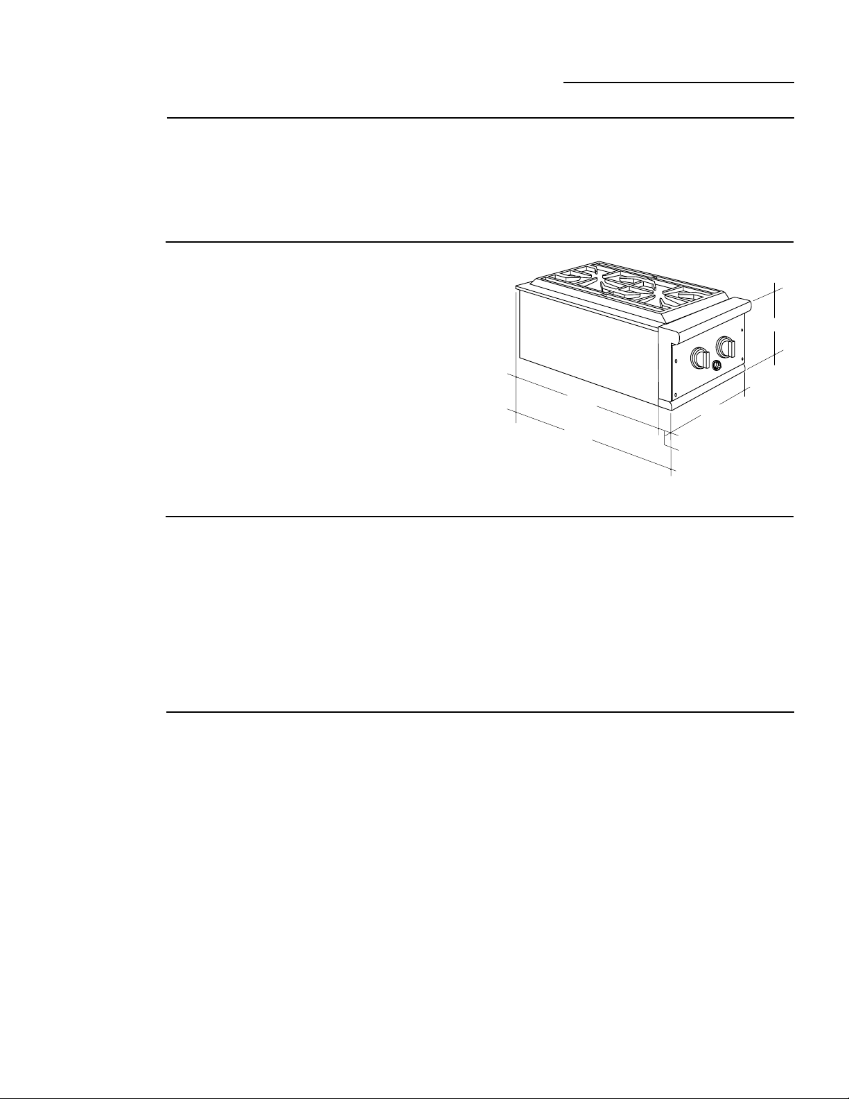
Dual Burner Outdoor Cooktop
Models
Available
Product
Dimensions
& Clearances
Accessories
Monogram Dual Burner Outdoor Cooktops
are factory set for LP or natural gas. Order the
model for your installation situation.
Liquid Propane
Model ZX2L SS
When installed on the side of a grill cart, allow
6" clearance at the rear and right side to
vertical combustible materials.
When installed in an enclosure, allow 6"
clearance at the rear and both sides to vertical
combustible materials.
When installed in a combustible enclosure,
the cooking surface should be 1" above
adjacent horizontal surfaces.
Both LP and Natural gas models may be
installed on a 27" wide portable grill cart. Both
models are shipped with support brackets to
secure the burner to the right side of the cart.
Accessories should be ordered with the burner
and be on site at the time of installation.
ZX27QDC – LP Quick Disconnect Tee
For installation onto a 27" cart.
Natural Gas
Model ZX2N SS
These models can be mounted to the right
side of a Monogram 27" wide grill which has
been installed on a cart.
These models can also be installed in a
combustible or non-combustible enclosure.
10-1/2"
23-3/4"
25-3/4"
ZX2TKYSS Trim Kit
For a built-in installation, the enclosure, can
be constructed of non-combustible (masonry)
material or of combustible material such as
wood. This trim kit conceals the back and side
edges of the opening.
ZX2JYSS Insulated Jacket
An insulated jacket is required when installing
into a combustible enclosure.
13"
2"
Advance
Planning
• Monogram Dual Burner Outdoor Cooktops
are designed to be installed on the right side
of a 27" grill cart or built into an enclosure.
• In a non-combustible (masonry) enclosure,
the burner drops into the opening. A solid
deck beneath is required for support from
the bottom.
• An insulated jacket is available to allow the
grill to be installed in a combustible
enclosure. The insulated jacket must be
supported from the bottom by a solid deck or
ledge on each side beneath the jacket.
• A trim kit is available for built-in installations
to conceal the back and sides of the opening.
Clearances:
• When installed on the side of a grill cart,
allow 6" clearance at the rear and right side
to vertical combustible materials.
• When installed in an enclosure, allow 6"
clearance at the rear and both sides to
vertical combustible materials.
• When installed in a combustible enclosure,
the cooking surface should be 1" above
adjacent horizontal surfaces.
3
Page 4
Design Information
Dual Burner Outdoor Cooktop
Choosing
the Location
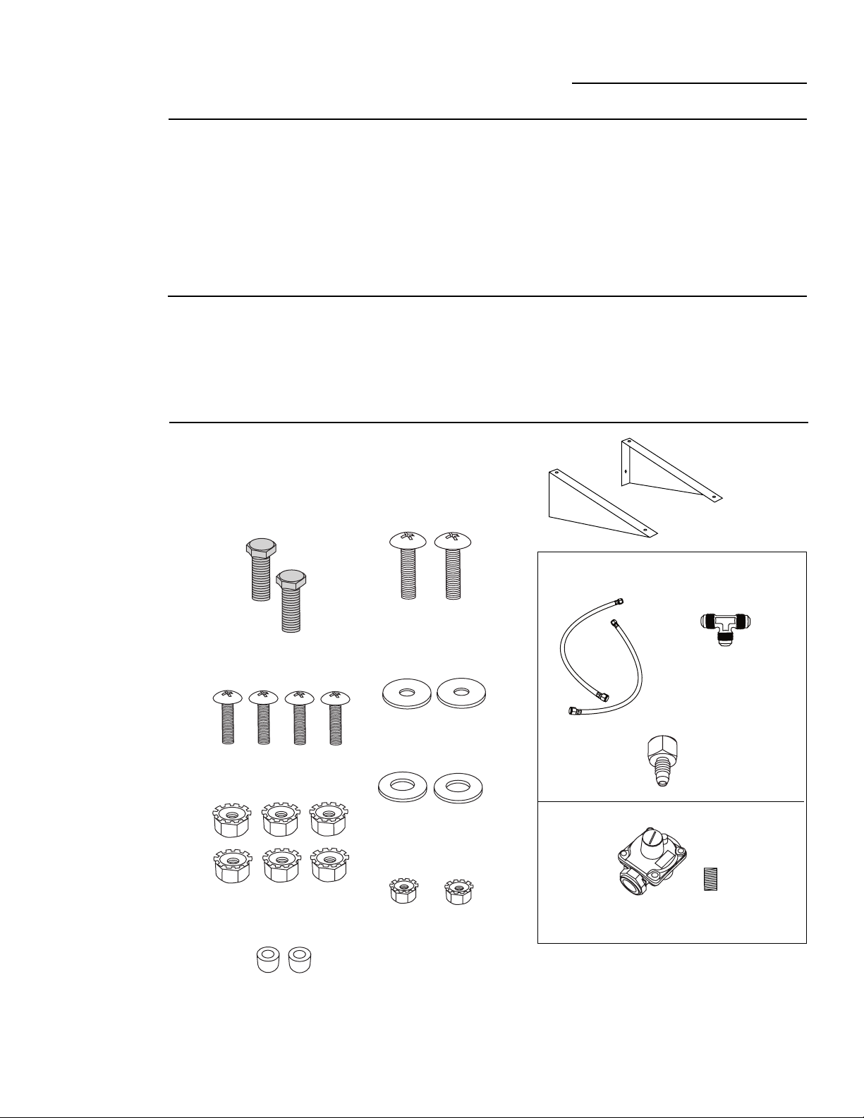
Tools &
Materials
Required
(Not supplied)
Step
1
Remove the
Packaging
• These cooktops are designed for outdoor use
only. Do not locate the cooktop in a building,
garage or other enclosed area.
• Ensure that fresh air ventilation is adequate.
• Consider exposure to wind and proximity to
traffic paths.
• The minimum clearances to combustibles
must be maintained at all times.
• Phillips head screwdriver
• Two adjustable pipe wrenchs
• 7/16" socket with extension
• Level
• Pliers
• Flat blade screwdriver (3/32" blade)
• Open the box and remove packaging.
• Remove the cover and grate.
• Remove white plastic tie-downs on burners.
• Open the hardware accessory carton and
check contents.
• Do not install an outdoor cooktop below
overhead unprotected combustible
construction.
• The installation must conform to local codes
or in the absence of local codes, with the
national fuel gas code, ANSI Z223.1a, latest
edition.
For Natural Gas Installations:
• Appropriate gas line to reach installation
location
• Pipe joint sealant, approved type and
resistant to LP gases
• Manual shut-off valve
Support Brackets
Count 2
LP MODELS
See Product to Determine Parts Used
1/4 - 20 x 1/2" Bolts
Count 2
10 - 24 x 3/8" Screws
Count 4
10 - 24 Lock Nuts
Count 6
# 10 x 1/4" Thick Round Spacers
Count 2
10 - 24 x 3/4" Screws
Count 2
#10 Flat Washers
Count 2
1/4" Flat Washers
Count 2
1/4 - 20 Lock Nuts
Count 2
3/8" Flare Tee and
Two 3/8" x 3/8" Flare Hoses
(On Models So Equipped)
3/8" NPT x 1/2"
Flare Fitting
NATURAL GAS MODELS
Regulator and
1/2" NPT Close Nipple
4
Page 5

Step
Support
Bracket
Gas Hose
1/4-20x1/2" Bolts
Bushing
1/4-20
Lock Nut
1/4-20
Lock Nut
1/4" Flat
Washers
10-24 Lock Nuts
10-24x3/8" Screws
2
Installation
Installation
Dual Burner Outdoor Cooktop
The cooktop burner is designed to fit onto
the right side of the 27" grill head.
• Open the grill lid and remove the right
cooking grate and Gourmet Radiant Tray (or
Lava Rock Tray).
On 27" Cart
(Skip this step if
you are installing
in an enclosure)
Secure Support Brackets to Grill
• Remove the cooktop burner cover, burner
grate and stainless steel aeration pan and
drip tray.
• Remove the two open top burners by
grasping the burner and pulling up and
towards the rear.
• Secure the support brackets to the cart using
two 1/4 - 20 x 1/2" bolts, 1/4" flat washers
and lock nuts as shown. Use a 7/16" socket
with extension to reach the front lock nut.
Secure Cooktop to Grill Head
• Install two 10 - 24 x 3/4" screws and #10
washers from inside the grill head. On the
outside of the grill head, install 1/4" round
spacers onto the bolt.
• Position the cooktop chassis on top of the
support brackets, aligning side mounting
holes with bolts. Push bolt through the
spacer and into the burner box. Secure with
lock nuts.
• Check to be sure the cooktop is level with
the grill head. Loosen mounting bolts and
adjust if necessary.
10-24x3/4 Screws
Washer
1/4" Spacer
10-24
Lock Nut
Secure Cooktop to Support Brackets
• Install the four 10 - 24 x 3/8" screws through
the inside of the burner box and through
the bracket. Secure with 10-24 lock nuts.
• Reinstall the cooktop burner, aeration pan,
burner grate and drip tray.
5
Page 6

Step
2A
Installation
Into An
Enclosure
(Skip this step
if burner is installed
on a grill cart)
• All built-in installations should be at least
35-1/2" above the floor.
Clearances to Combustibles:
• Allow at least 6" clearance from the back and
sides to any combustible material.
• Allow at least 1" clearance below the cooking
surface on all sides.
Installation in a combustible enclosure:
• Installation into a combustible enclosure
requires the ZX2JYSS insulated jacket.
• The insulated jacket must be supported from
the bottom by a solid deck or ledge on each
side beneath the jacket.
Installation in a non-combustible enclosure:
• In a non-combustible (masonry) enclosure,
the burner drops into the opening. A solid
deck beneath is required for support from
the bottom.
Installation
Dual Burner Outdoor Cooktop
2x2
Opening
for Gas
Supply
Line
Combustible enclosure with Insulated Jacket
2x2
Opening
for Gas
Supply
Line
Non-combustible enclosure
15-3/8"
24-5/8"
1"
11"
13-1/8"
10-3/8"
1-1/8"
23-5/8"
To install trim kit ZX2TKYSS:
• Remove the cover and burner grate.
• Place side trim and rear trim pieces over the
burner edges, overlapping the countertop
surface.
• Install screws from the inside of the burner
and through the trim. 3 each on all sides.
NOTE: The trim kit is not designed to support
the weight of the Dual Range Top Burner.
Support from the bottom must be provided.
6
Page 7

Installation
3/8" Flare Tee
From
Regulated
L.P. Tank
To Cooktop
To Manifold
of Grill
1/2" NPT x
3/8" Flare Fitting
Dual Burner Outdoor Cooktop
Step
3
Provide
Gas
Supply
LP GAS MODELS
Go to Step 3A
For Natural
Gas Model
Connections
WARNING
When storing the LP burner indoors,
disconnect the LP tank. Store the tank
outdoors in a well ventilated area.
Do not store spare LP tanks near or below
the burner installation.
For installation with a 27" LP gas grill that
does not feature the new Quick Disconnect
coupling.
• Completely close the main valve on the LP
tank supplying the grill.
• Apply joint compound to the threaded end
of the cooktop gas inlet.
• Tighten the 1/2" NPT x 3/8" flare fitting to
the cooktop gas outlet. Do not use threading
compound on the male threads.
• Attach hose to end of fitting and tighten.
• Route the hose through the hole with
protective bushing on the side of the grill
cart.
• Attach the hose ends from the grill and the
cooktop to the ends of the supplied 3/8"
flare tee as shown.
• Attach the original LP Regulator hose
assembly to the 3/8" flare tee as shown.
• Go to “Test for Leaks” Step 4.
PRODUCT STORAGE
LP Connection
with ZX27QDC
Kit For Quick
Disconnect
Coupling
System
For Installation with a 27" LP Gas Grill
featuring Quick Disconnect couplings.
• Completely close the main valve on the LP
tank supplying the grill.
• Apply joint compound to the threaded end
of the cooktop gas inlet.
• Tighten the 1/2" NPT x 3/8" flare fitting to
the cooktop gas outlet. Do not use threading
compound on the male threads.
• Attach hose to end of fitting and tighten.
NOTE: To connect the Quick Disconnect
couplings, pull back and hold the outer sleeve
of the female coupling while inserting the
male hose end. Release the outer sleeve to
lock. To test the connection, firmly grasp each
part and attempt to pull apart. Once locked,
they should not separate.
• Route the cooktop LP hose through the
panel bushing on the right side of the cart.
• Insert the male hose end from the cooktop
burner into one end of the quick disconnect
tee.
1/2" NPT x
3/8" Flare
Fitting
24" Quick
Disconnect Hose
To Manifold
of Grill
To L.P.
Regulator
• Attach the hose from the grill to the opposite
female end of the quick disconnect tee.
• Secure the bottom male end of the quick
disconnect tee to the female quick disconnect
LP tank regulator assembly.
• Go to “Test for Leaks” Step 4.
Quick
Disconnect
Tee
7
Page 8

Step
3A
Provide
Gas Supply
NATURAL GAS MODELS
The burner and its individual shut-off valve
must be disconnected from the gas supply
during any pressure testing of the system at
test pressures in excess of 1/2 PSIG.
The burner must be isolated from the gas
supply system by closing its individual shut-off
valve during any pressure testing of the system
at test pressures equal to or less than 1/2
PSIG.
The installation of these burners must conform with local codes or, or in the absence of
local codes, with the National fuel gas code,
ANSI Z223.1a, latest edition.
Operating pressure is 4" W.C.
Supply pressure should be 5" to 14" W.C. If
pressure is more than 14" W.C. a step down
regulator is required.
Installation
Dual Burner Outdoor Cooktop
Regulator
4.0" W.C.
1/2 NPT
Close Nipple
• Install a manual gas shut-off valve in an easily
accessible location.
• Connect the 1/2 NPT coupling to the
burner gas inlet.
• Make connections as shown.
• Check to be sure the regulator arrow points
in the direction of gas flow, towards the grill
and away from the gas supply.
Check with local gas utility or with local codes
for instructions on installing gas supply lines.
Be sure to check on type and size of run and
how deep to bury the line. If the gas line is too
small, the burner will not function properly.
8
Page 9

Installation
Dual Burner Outdoor Cooktop
Step
4
Test for
Leaks
WARNING
A complete gas tightness check must be
performed at the installation site. DO NOT
USE A FLAME TO CHECK FOR GAS
LEAKS.
• Do not use the burner until all connections
have been leak tested.
• Repeat leak test after each LP tank change or
gas re-connect.
• Check to be sure the main valve on the LP
tank or the shut-off valve is in the “OFF”
position.
• Make a soap solution of one part liquid
detergent and one part water.
TEST FOR LEAKS
The valve panel must be removed to check
the valves and fittings.
• All control valves should be in the “OFF”
position.
• Remove the knobs.
• Remove the 4 screws holding the valve panel
to the burner.
• Pull the panel outwards and unplug the wire
from the back of the rotary igniter.
TO TEST:
• Apply the soap solution around all
connections, valve and tubing.
• Turn the gas supply on.
• Check all connections from the supply line
or LP tank up to and including the manifold
pipe assembly.
• If a leak is detected, turn gas supply off and
tighten fittings. Turn the gas on and check
again.
• To re-install the valve panel, re-connect the
igniter wire and secure the panel with
original screws.
Step
5
Lighting
the Burner
WARNING
the burner if the odor of gas is present.
CAUTION: Keep hands and face as far away
from the burner as possible when lighting.
• Remove burner cover.
• Turn all knobs to “OFF” position.
• Turn gas supply on at the LP tank or shut-off
valve.
NOTE: When lighting the burner for the first
time or after a LP tank change, up to 20
seconds may be required to purge air from
the lines.
• Push and turn control knob counter-clockwise
to “LITE” position, turn the small igniter
knob next to the burner knob clockwise.
NOTE: The spark will produce a snapping
sound. This is normal.
• If the burner does not light within 4 seconds,
turn knobs to “OFF and wait 5 minutes for
the gas to dissipate before trying again.
• If the burner does not light after several
attempts, the burner can be lit with a match.
Do not attempt to light
TO MATCH LIGHT:
• Remove the burner grate.
• Strike match and hold adjacent to burner
port.
• Push and turn the control knob to “LITE”.
• Rotate the control knob to desired setting.
• Replace grate.
ALWAYS TURN GAS SUPPLY OFF AT THE
SHUT-OFF VALVE OR LP TANK WHEN
NOT IN USE.
9
Page 10

Installation
3/8"
1-1/2"
Proper Flame
Burner
Dual Burner Outdoor Cooktop
Step
6
Adjusting
the Burners
Adjustments should not be required, unless
vibration during transit or variations in local
gas supply make minor adjustments necessary.
Adjustments must be made by a qualified
technician at the time of installation. Extreme
care should be used if adjustments are made
after installation.
• Push and turn the burner control knobs to
the “LITE” position. Push and turn the small
ignitor knob clockwise.
• Flames should be blue and stable with no
yellow tips, excessive noise or lifting from the
burner. If any of these conditions exist, turn
control to off and check air shutter and
burner ports for debris or spider webs.
TO ADJUST:
• If the flame is yellow, indicating insufficient
air, turn the air shutter to allow more air to
the burner.
• If the flame is noisy and tends to lift away
from the burner, there is too much air. Turn
the air shutter to reduce the opening.
Air Shutter
Venturi Tube
Burner
Finalize
Installation
Low setting Adjustment:
Minor adjustments may be required due to
fluctuations in local gas pressure. Adjustments
to increase or decrease gas flow may be
necessary.
• Turn the control knob to the lowest setting,
all the way counter-clockwise.
• Remove the knob by pulling straight out.
• Insert a thin-blade flat screwdriver into the
valve shaft and hold. (3/32" blade width
recommended.)
• Grip the shaft with pliers and turn counterclockwise to lower the flame, or clockwise to
increase the flame.
• When the desired setting is made, replace the
knob and turn burner off.
• Place aeration pan over the burners.
• Place the cast iron grate over the opening.
• Place cover over the top when not in use.
Bezel
Valve Stem
WARNING:
Always check the low flame size for stability. A
burner flame which is too small may go out or
be extinguished easily. This can cause unburned gas to escape and cause a hazardous
condition.
10
Page 11

Notes
Dual Burner Outdoor Cooktop
11
Page 12

Monogram.
General Electric Company
Louisville, KY 40225
Note: While performing installations described in this book,
safety glasses or goggles should be worn.
To obtain specific information concerning any
Monogram product or service, call GE Answer Center
consumer information service at 800.626.2000—any
time, day or night.
For Monogram local service in your area, call
1-800-444-1845.
NOTE: Product improvement is a continuing endeavor at General
®
Electric. Therefore, materials, appearance and specifications are subject
to change without notice.
®
Pub. No. 49-8842-1
Dwg. No. 164D3333P082
© 2000 GE Appliances
Printed in USA
(N.D. 660) 8/00
10746-Rev. 2
 Loading...