

Page 1

If you have questions, call 800.GE.CARES or visit our website at: www.monogram.com
Installation
Instructions
Professional Gas Cooktops
48" Natural Gas Models
ZGU48N4G
ZGU48N6R
ZGU48N6D
48" LP Gas Models
ZGU48L4G
ZGU48L6R
ZGU48L6D
36" Natural Gas Models
ZGU36N6
ZGU36N4R
ZGU36N4D
36" LP Gas Models
ZGU36L6
ZGU36L4R
ZGU36L4D
Page 2
Installation Instructions
CAUTION:
THESE COOKTOPS SHOULD BE INSTALLED
IN CONJUNCTION WITH A SUITABLE
OVERHEAD VENT HOOD. Due to the high heat capacity
of this unit, particular attention should be paid to the
hood and duct work installation to assure it meets
local building codes.
MISE EN GARDE :
CES CUISINIÈRES DOIVENT ÊTRE
MONTÉES CONJOINTEMENT AVEC UNE
HOTTE À ÉVACUATION DE PLAFOND APPROPRIÉE.
Étant donné la grande capacité thermique de cet
appareil, une attention particulière doit être portée
au montage de la hotte et du système de gaines pour
s’assurer qu’il est conforme aux codes du bâtiment
locaux.
Standard countertop and island installations:
A 1200 CFM hood is recommended for 48" cooktops.
A 600 CFM hood is recommended for 36" cooktops.
Hoods should be 24" min. deep and the same width
as the cooktop.
Island installations:
Check local building codes for the proper method of
gas cooktop installation. Local codes vary. Installation,
electrical connections and grounding must comply
with applicable codes. In the absence of local codes,
the cooktop should be installed in accordance with the
National Fuel Gas Code ANSI 223.1-1990 and National
Electrical Code ANSI/NFPA 70-1990.
CAUTION:
These cooktops are extremely heavy. Due
to the weight and size of the cooktop and
to reduce the risk of personal injury or damage to the
product, TWO PEOPLE ARE REQUIRED FOR PROPER
INSTALLATION.
MISE EN GARDE :
Ces cuisinières sont extrêmement lourds.
Tout démontage réduira considérablement
leur poids. En raison du poids et de la taille de la
cuisinière, dont la manipulation risque d’entraîner
des lésions corporelles ou des dommages au produit,
DEUX PERSONNES SONT NÉCESSAIRES POUR
PROCÉDER À UN MONTAGE ADÉQUAT.
BEFORE YOU BEGIN
Read these instructions completely and
carefully.
• IMPORTANT – Save these instructions for
local inspector’s use.
• IMPORTANT – Observe all governing codes
and ordinances.
• Note to Installer – Be sure to leave these
instructions with the Consumer.
• Note to Consumer – Keep these instructions for
future reference.
• Skill Level – Installation of this cooktop requires
basic mechanical and electrical skills.
• Completion time – 1 to 3 hours.
• Proper installation is the responsibility of the installer.
• Product failure due to improper installation is not
covered under the Warranty.
WARNING:
This appliance must be properly grounded.
See “Electric Supply”, page 6.
AVERTISSEMENT :
Cet appareil doit être mis à la terre
adéquatement. Voir la section « Alimentation
électrique » à la page 6.
For Monogram local service in your area,
1.800.444.1845.
For Monogram Service in Canada, call
1.888.880.3030.
For Monogram Parts and Accessories, call
1.800.626.2002.
If you received a damaged cooktop, you should contact
your dealer.
In the Commonwealth of Massachusetts:
• This product must be installed by a licensed plumber
or gas fitter.
• When using ball type gas shut off valves, they shall
be T-handle type.
• A flexible gas connector, when used, must not
exceed 3 feet.
2
Page 3
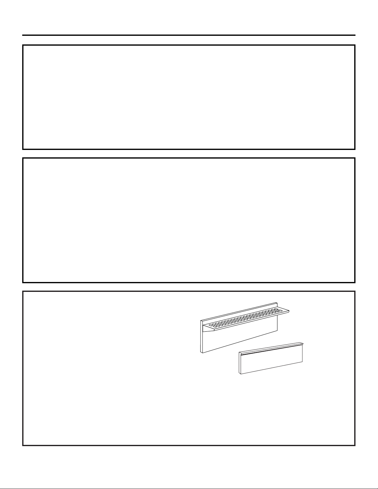
22" High Backsplash With
Warming Shelf
12" High Backsplash
INSTALLATION NOTE:
A custom backspash may be constructed of non-combustible back wall materials such as ceramic tile, brick, marble
or other stone.
CONTENTS
Design Information
Models Available ..............................................................3
Accessory Requirements ................................................3
Product Dimensions and Clearances ............................4
Installation Options ..........................................................5
Advance Planning .......................................................... 5
Installation Preparation
Tools and Materials Required ........................................6
Power Supply Locations ..................................................6
Installation Instructions
Step 1, Remove Packaging ..............................................7
Step 2, Cut the Countertop Opening ..............................7
Step 3, Install the Cooktop ..............................................8
Step 4, Connect Cooktop to Gas......................................8
Step 5, Connect Electrical................................................9
Step 6, Assemble Burners, Check Ignition....................9
Finalize Installation..........................................................10
Installation Checklist ......................................................10
Install the Cooktop Backsplash Accessory ................11
MODELS AVAILABLE
These cooktops are factory set for either natural
gas or liquid propane gas. Order the model for your
installation situation.
48" Natural Gas Models:
ZGU48N4G – 4 gas burners, grill and griddle
ZGU48N6R – 6 gas burners and grill
ZGU48N6D – 6 gas burners and griddle
48" Liquid Propane Gas Models:
ZGU48L4G – 4 gas burners, grill and griddle
ZGU48L6R – 6 gas burners and grill
ZGU48L6D – 6 gas burners and griddle
36" Natural Gas Models:
ZGU36N4D – 4 gas burners and griddle
ZGU36N4R – 4 gas burners and grill
ZGU36N6 – 6 gas burners
36" Liquid Propane Gas Models:
ZGU36L4D – 4 gas burners and griddle
ZGU36L4R – 4 gas burners and grill
ZGU36L6 – 6 gas burners
BACKSPLASH ACCESSORIES
All models require 12" min. clearance to a vertical
combustible surface at the rear. A backsplash
accessory is available for installations with less than
12" clearance to the back wall. Order a 12" high
backsplash or 22" high backsplash with warming shelf.
Backsplash for 48" Models:
ZX12B48HSS – 12" high backsplash
ZX22B48HSS – 22" high backsplash with warming shelf
(2 piece)
Backsplash for 36" Models:
ZX12B36HSS – 12" high backsplash
ZX22B36HSS – 22" high backsplash with warming shelf
(2 piece)
3
Design Information
Page 4
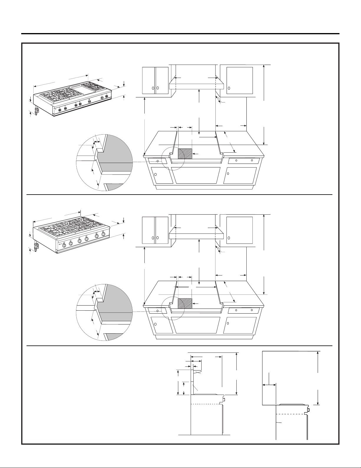
48" Wide Models
36" Wide Models
36" Min.
to
Combustibles
0" Clearance
12" Min. to Combustibles or
0" Min. to Combustibles
with 12" or 22" Backsplash
4
PRODUCT DIMENSIONS AND CLEARANCES
Design Information
47-7/8"
AR
RE
T
N
O
R
F
m
a
gr
o
on
M
Allow Additional Clearance
Below the Cooktop Burner
Box for the Regulator and
Gas Connections
2-1/2"
35-7/8"
26-5/8"
48" Wide Hood
R
A
RE
T
N
O
R
F
R
A
RE
NG
TI
A
T
N
HE
O
R
F
8-7/16"
Refer to Hood
Installation
18" Min.
2"
Instructions
17"
13" Max.
12" Min. to
Combustible
Material
Each Side
36" Min. to
Combustible
Material From
Cooking
Surface
7/8"
46-1/8"
Cooking Surface
22-3/4" Min.
Electric/Gas
Supply
8"
26-5/8"
36" Wide Hood
8-7/16"
Allow Additional Clearance
Below the Cooktop Burner
Box for the Regulator and
Gas Connections
18" Min.
Refer to Hood
Installation
Instructions
13" Max.
12" Min. to
Combustible
Material
2"
7"
Each Side
36" Min. to
Combustible
Material From
Cooking
Surface
1/2"
2-1/2"
35"
Cooking Surface
22-3/4" Min.
Electric/Gas
Supply
8"
9-1/2"
3/4"
22"
12"
26-5/8"
22" High
Backsplash
36" Min.
to Combustibles
with Shelf
12" High Backsplash
Page 5

1/2" Above Adjacent
Countertops.
Front Projects Outward as Shown
From Standard Depth Cabinets.
Cooktop
1/2" Above Adjacent
Countertops.
Front Flush With Cabinets - a Minimum
of 25-3/4" Cabinet Depth Required
Flush With Cabinet Front
Cooktop
ADVANCE PLANNING
Refer to “Dimensions and Clearances” for appropriate
placement and necessary clearances when planning
the installation.
• Cabinetry cannot be installed directly above the
cooktop.
• We recommend the installation of a vent hood above
the cooktop surface.
– The vent hood must be at least 24" deep.
– The vent hood must be at least the same width as
the cooktop.
– For 48" models, we recommend the vent hood
blower be 1200 CFM.
– For 36" models, we recommend the vent hood
blower be 600 CFM.
• Refer to hood installation instructions for height
dimensions.
• Working areas adjacent to the cooktop should have
18" minimum clearance between countertop and
cabinet bottom.
• Clearance between cooktop and side wall or
combustible material must be at least 12" on
each side.
• These cooktops require 8" free space below the
countertop to house the burner box. Additional
clearance is required below the burner box for the
gas regulator and connections. Connections should
be routed to limit interference with drawers or other
cabinetry features.
• Allow 12" min. clearance at the back to combustible
materials.
• Allow 36" min. above the cooking surface to
combustible materials.
• Installation must conform with local codes. In the
absence of local codes, the gas cooktop must comply
with the National Fuel Gas Code, ANSI Z223.1/NFPA.54,
latest edition. In Canada, installation must conform
with the current Natural Gas Installation Code,
CAN/CGA-B149.1 or the current Propane Installation
Code, CAN/CGA-B149.2, and with local codes where
applicable. This cooktop has been design-certified by
CSA International according to ANSI Z21.1, latest
edition and Canadian Gas Association according to
CAN/CGA-1.1 latest edition.
5
INSTALLATION OPTIONS
These cooktops can be installed in standard 24" or
deeper 25" cabinets.
• In 24" deep cabinets, the front of the cooktop will
project approximately 1-7/8" beyond the front of the
countertop.
• In 25" deep cabinets, the cooktop will be flush with
the front of the countertop.
• The stainless surface of the cooktop will be 1/2"
higher than adjacent countertop.
• Cooktop fits flush to rear of cutout; no additional
support is required.
Installation Preparation
26-5/8"
22"
High
Back
Countertop
Level
8-7/16"
Allow Additional Clearance
Below the Burner Box for
Gas Connections
4" to Center Line
of Gas Inlet
on the Left
12"
1/2"
1/2"
Cabinet Face - Projecting Control Panel
Cabinet Face - Flush Control Panel
22" High
Backsplash
with Shelf
12" High
Backsplash
22-3/4"
23-1/4"
2-1/2"
Page 6

POWER SUPPLY LOCATIONS
Gas Supply:
• The pressure regulator must be connected in series with the
manifold of the cooktop and must remain in series with the
supply line regardless of the type of gas being used.
• The natural gas models are designed to operate at 5" water
column pressure. A regulator is required at the natural gas
source to provide a maximum of 7" water pressure to the
cooktop regulator.
• The liquid propane models are designed to operate at 10"
water column pressure. A regulator is required at the LP
source to provide a maximum of 14" water pressure to the
cooktop regulator.
• These gas cooktops are supplied with 1/2" NPT female gas
connection located at the left rear corner.
• A minimum 5/8" dia. metal flexible line is required.
– Use 5-foot long 5/8" flexible metal tubing. (Length must
comply with local codes.)
• For rigid connection, locate the pipe stub within area shown.
• Install a manual shut-off valve in the gas line, in an easily
accessible location.
Electric Supply:
These cooktops must be supplied with 120 volt, 60 Hz., and
connected to an individual, properly grounded branch circuit
protected by a 15 amp circuit breaker or time delay fuse.
The power cord of this appliance is equipped with a
three-prong (grounding) plug which mates with a standard
three-prong grounding wall receptacle to minimize the
possibility of shock hazard from this appliance.
If the electrical service provided does not meet the above
specifications, it is recommended that a licensed electrician
install an approved outlet.
DO NOT, UNDER ANY CIRCUMSTANCES, CUT OR REMOVE
THE THIRD (GROUND) PRONG FROM THE POWER CORD.
DO NOT USE AN EXTENSION CORD WITH THIS APPLIANCE.
• Locate the electric supply within the area shown or within
reach of the cooktop’s six foot power cord.
• To avoid tangling cord with items stored in the cabinet, locate
the receptacle on rear wall, inside the cabinet.
Three Prong Receptacle
Receptacle Box Cover Plate
Three Prong Plug
6
TOOLS REQUIRED
• Saw
• Measuring tape
• Carpenter’s square
• Large flat-blade screwdriver
• Pipe wrench
Gas Line
to Cooktop
Locate Gas Supply 2" Maximum
Protrusion From Wall or on Floor 2" From Wall
2"
7" for 36" Models
17" for 48" Models
16"
MATERIALS REQUIRED (not supplied)
• Pipe and fittings as required
• Manual gas line shut-off valve
• Gas pressure regulator (supplied)
• Gas-resistant pipe joint sealant
• 5 foot, 5/8" AGA-certified flexible metal gas supply line
(length must comply with local codes)
– If required by local codes, use solid pipe fittings.
NOTE: Purchase new flexible line. DO NOT USE OLD,
PREVIOUSLY USED FLEXIBLE LINE.
Installation Preparation
Page 7

Measure carefully when cutting the countertop.
Make sure sides of the opening are parallel.
• These cooktops require 8" free space below the
countertop to house the cooktop burner box.
• Allow additional clearances below the burner box
to install the regulator and make house supply
connections. Use a 90° elbow to route the gas
connections and limit interference with drawers
or other cabinetry features.
• These cooktops are designed to hang from the
countertop from its rear and side flanges.
• Smooth any rough edges on the countertop before
installing the cooktop.
– Formica countertop edges must be finished.
The countertop must be strong enough to
support the weight of the cooktop.
• Support cleats can be secured to cabinet sides.
OR
• Build a support deck or box inside the cabinet which
will support the weight of the cooktop.
– Build the support box using a solid material, cut a
5" x 5" square in the left rear corner for the gas inlet
and power cord clearances.
• After the cooktop is installed, the bottom front edge of
the cutout may need to be covered. Install a trim strip
from the cabinet manufacturer to match cabinetry.
48" wide models are designed to fit in 48" or wider base cabinets 36" wide models are designed to fit in 36" or wider base cabinets
Allow Additional
Clearance Below
the Cooktop Burner
Box for the Regulator
and Gas Connections
8"
2-1/2"
7/8"
46-1/8"
22-3/4"
8-7/16"
26-5/8"
47-7/8"
22"
12"
1/2"
Available
Backsplash
Install a Matching Trim
Strip to Cover the Cut
Edge Below the Cooktop
8"
2-1/2"
1/2"
35"
22-3/4"
26-5/8"
8-7/16"
35-7/8"
22"
12"
1/2"
Available
Backsplash
Allow Additional
Clearance Below
the Cooktop Burner
Box for the Regulator
and Gas Connections
Install a Matching Trim
Strip to Cover the Cut
Edge Below the Cooktop
7
REMOVE PACKAGING
Use a hand-truck to move this cooktop.
Before moving the cooktop indoors:
• Remove outer carton and packing.
• Remove the straps holding the cooktop to the skid.
• Remove the grates and drawer, below the knobs
(on grill and griddle models).
• Remove grill and/or griddle covers. DO NOT ATTEMPT
TO REMOVE A GRILL OR GRIDDLE ASSEMBLY.
• Flatten the carton and use a piece as a pad on the
bottom and back of the hand-truck. Lift the cooktop onto
the hand-truck standing on its end, with the bottom of
the cooktop resting against the back of the hand-truck.
Move the cooktop indoors:
If door and passageways into the installation location are
less than 30" wide, remove the cooktop knobs.
STEP 1
CUT THE COUNTERTOP OPENING
STEP 2
Installation
Adjacent Cabinet
and Countertop
Counter Sunk
Screws
Page 8

Alternate Bracket
Screw Holes
“L” Bracket
8
INSTALL COOKTOP
• Lower the cooktop into the opening. Make sure the
cooktop is evenly seated and supported. A side frame
gasket will seal the cooktop to the countertop.
• “L” brackets with screws are provided to secure the
cooktop to the countertop or to adjacent cabinetry.
– Alternate screw hole locations on the sides of the
cooktop allow for varying thicknesses of countertops
or side cleats.
• Select the bracket location; secure the bracket to the
cooktop with 2 screws.
• Drive one screw through the bottom of the “L” bracket
and into countertop or side cleats.
STEP 3
CONNECT COOKTOP TO GAS
A manual shut-off valve must be installed where
it will be accessible.
Assure that gas is turned off at the shut-off valve.
• Install the supplied pressure regulator onto the end
of the gas inlet.
• You can install a 90° elbow (not supplied) onto the
gas inlet and route the gas connections to avoid
interference with drawers or other cabinetry features.
• Make sure the regulator is installed in the right
direction. See arrow on the underside of the regulator.
NOTE: Instead of using solid piping to connect to
pressure regulator, an approved flexible metal appliance
connector may be used between the pipe stub and the
shut-off valve to the pressure regulator, if local codes
permit.
• Appropriate flare nuts and adapters are required at
each end of the flexible connector.
WARNING: Do not use a flame to
check for gas leaks.
AVERTISSEMENT :
Il ne faut pas utiliser de flamme pour vérifier
s’il y a des fuites.
IMPORTANT: Disconnect the cooktop and the individual
shut-off valve from the gas supply piping system during
any pressure testing of that system at test pressures
greater than 1/2 psig. Isolate the cooktop from the gas
supply piping system by closing the individual manual
shut-off valve to the cooktop during any pressure testing
of the gas supply piping system at test pressures equal
to or less than 1/2 psig.
• Turn on gas and check for leaks:
–Use a liquid leak detector at all joints and connections
in the system.
STEP 4
Installation
Note: Pipe stub extends
about 1" below burner box.
Cooktop Burner Box
Gas Inlet
Regulator
(Supplied)
Solid Piping
or Flexible
Connector
Shut-Off
Valve
Pipe Stub From
House Gas Supply
Page 9

Assemble burners as shown. Check to be sure that
burner heads and caps are securely seated. Pin(s) must
completely engage holes to ensure proper assembly.
• Check for proper ignition:
– Push in one control knob and turn 90° to Lite position.
– The igniter will spark and the burner will light; the
igniter will cease sparking when the burner is lit.
– First test may require some time while air is flushed
out of the gas line.
– Turn knob to OFF.
– Repeat the procedure for each burner.
IMPORTANT: If the igniter electrodes continue to
spark after the burners are lit, check that each
burner component is assembled and seated properly
by observing constant gaps between each layer.
Disassemble and reassemble as required.
• Burner flames should be blue and stable with no yellow
or yellow tips, excessive noise or lifting of the flame
from the burner. If any of these conditions exist, check
that the burner ports are not blocked.
To aid reassembly, each brass burner head is
marked with a clock face. Replace the burner
head with the arrow pointing to the rear of the
cooktop (12 o’clock position).
9
CONNECT ELECTRICAL
Plug power cord into properly grounded receptacle.
STEP 5
ASSEMBLE BURNERS, CHECK IGNITION
STEP 6
Installation
Burner Cap
Burner Head
(Brass)
Locator Pins
Burner Ring
(Aluminum)
Page 10

10
FINALIZE INSTALLATION
Place the burner grates over the burners. Press corner
of the grate to the cooktop. The grates should be seated
and should not rock.
The grill and griddle are secured with screws at the
front. They are designed to be stationary and should not
be removed.
The griddle has two leveling screws beneath the rear
flue cover that can be used to adjust to the desired slope.
The center screw is for shipping purposes only and can
be removed.
Installation
INSTALLATION CHECKLIST
❑ Double check to make sure everything in this manual
has been completed. Rechecking steps will ensure
safe use of the cooktop.
❑ Make sure all controls are left in the OFF position.
❑ Make sure the flow of combustion and ventilation air
to the cooktop is unobstructed.
❑ The serial plate for your cooktop is located beneath
the ledge trim on the left side, just above the left knob.
In addition to the model and serial numbers, it tells
you the ratings of the burners and the type of fuel
and pressure the cooktop was adjusted for when it
left the factory.
❑ When ordering parts, always include the serial
number, model number and a code letter to ensure
proper replacement parts.
❑ Recheck Steps:
Double check to make sure everything in this manual
has been completed. Rechecking steps will ensure
safe use of the cooktop.
Page 11

11
INSTALL 9” or 12” HIGH BACKSPLASH
• Install and level the range or cooktop according to the
installation instructions.
• Remove the backsplash packaging. Select the back, wall
mount panel with mounting screw slots.
• Mark a horizontal line on the wall, 1/8" above the
range/cooktop backguard.
• Use wood screws or fasteners (not supplied) to secure
the back section to the wall. Slide the panel up or down
to provide the 1/8" gap between the top of the
range/cooktop and the bottom of the backsplash.
This 1/8" gap allows the appearance or front section
to overlap the mounted rear panel.
• Secure the appearance panel to the mounted back
section with the #8 self-tapping screws provided.
Install 3 screws on each side and 5 across the top.
INSTALL 22” HIGH BACKSPLASH
• Install and level the range or cooktop according to the
installation instructions.
• Remove the backsplash packaging. Select the back, wall
mount panel with mounting screw slots.
• Mark a horizontal line on the wall, 1/8" above the
range/cooktop backguard.
• Use wood screws or fasteners (not supplied) to secure
the back section to the wall. Slide the panel up or down
to provide the 1/8" gap between the top of the
range/cooktop and the bottom of the backsplash.
This 1/8" gap allows the appearance or front section
to overlap the mounted rear panel.
• Attach the shelf to the front section of the backsplash
using screws and nuts supplied.
• Secure the appearance panel to the mounted back
section with the #8 self-tapping screws provided.
Install 3 screws on each side and 5 across the top.
#
#
Installation
WARNING:
The back section must be securely fastened to
the wall. Failure to do so could cause damage or
personal injury. Maximum shelf weight capability
is 10 lbs.
AVERTISSEMENT :
La section arrière doit être fixée solidement
sur le mur. Le défaut de procéder ainsi peut
causer des dommages matériels ou des lésions
corporelles. La capacité de charge maximale
de l’étagère est de 4,5 kg (10 lbs ).
Front section
Supplied
#8 Screws
Back
section
Slots for Vertical
Adjustment
Holes
Nut
Screw
Supplied
8 Screws
Back section
1/8"
Backguard
Front section
Back
section
Back
section
1/8"
Backguard
Slots for
Vertical
Adjustment
Supplied
8 Screws
Page 12

Pub. No. 49-80225-3
Part No. 164D4290P377
17713 Rev. C
12-06 JR
NOTE: While performing installations described in this book,
safety glasses or goggles should be worn.
For Monogram®local service in your area, call
1.800.444.1845.
NOTE: Product improvement is a continuing endeavor at
General Electric. Therefore, materials, appearance and
specifications are subject to change without notice.
GE Consumer & Industrial
GE Appliances
General Electric Company
Louisville, KY 40225
ge.com
©2006 GE Company
 Loading...