

ISTRUZIONI D’USO
INSTRUCTIONS FOR USE
TAVOLO FERMALIEVITAZIONE
RETARDER-PROVER TABLES
“PLANET” Series
BFL
TAL / H
Manual_FL06 Rev.01 11-2014
www.gemm-srl.com

TALH / BFL _FL06_IT-EN Rev.01 11-2014 pag. 2

SOMMARIO / INDEX
1. INFORMAZIONI GENERALI
5
GENERAL INFORMATION
32
1.1 – Dati di marcatura / Marking
1.2 – Dichiarazione di conformità / Declaration of conformity
1.3 – Garanzia / Warranty
1.4 – Assistenza / After-sales service
1.5 – Utilizzo e conservazione del manuale / How to use and keep the manual
1.5.1 – Simboli utilizzati nel presente manuale / Symbols used in this manual
1.6 – Descrizione del personale / Personnel
2. DESCRIZIONE DELLA MACCHINA
9
MACHINE DESCRIPTION
36
2.1 – Dati tecnici / Technical data
2.2 – Descrizione dell’abbattitore ed uso previsto / Description of blast chiller and it use
2.2.1 – Componenti principali / Main parts
2.3 – Rumore / Noise
2.4 – Condizioni ambientali / Ambient conditions
3. SICUREZZA
14
SAFETY
41
3.1 – Avvertenze generali / General warnings
3.2 – Controindicazioni d’uso / Improper use
3.3 – Dispositivi di protezione / Safety devices
3.4 – Funzioni di arresto / Stop functions
4. TRASPORTO E MOVIMENTAZIONE
18
TRANSPORT AND HANDLING
45
4.1 – Trasporto dell’abbattitore / Transport
4.2 – Movimentazione dell’abbattitore imballato / Handling the packed blast chiller
4.2.1 – Peso e ingombro dell’abbattitore / Weight and dimensions
4.2.2 – Mezzi necessari / Means requie
5.
INSTALLAZIONE
20
INSTALLATION
47
5.1 – Predisposizione all’installazione / Preparation for installation
5.2 – Disimballaggio / Unpacking
5.2.1 – Mezzi necessari / Means required
5.2.2 – Procedura di disimballaggio / Unpacking procedure
5.3 – Movimentazione dell’abbattitore / Handling the blast chiller
5.3.1 – Mezzi necessari / Means required
5.3.2 – Procedura di movimentazione dell’abbattitore disimballato / Handling the unpacked blast chiller
5.4 – Montaggio dell’abbattitore / Blast chiller assembly
TALH / BFL _FL06_IT-EN Rev.01 11-2014 pag. 3

6. ISTRUZIONI ARMADIO FERMALIEVITAZIONE
22
INSTRUCTIONS FOR RETARDER-PROVER CABINET
49
6.1 – Verifiche preliminari - Preliminary checks
6.2 – Funzionamento manuale - Manual operation
6.3 – Funzionamento automatico - Automatic operation
6.4 – Impostazione ciclo - Cycle setting
6.5 – Ciclo automatico - Automatic cycle
6.6 – Limiti impostazioni - Setting limits
6.7 – Allarmi - Alarms
7. TABELLA PARAMETRI
27
PARAMETER TABLE
54
8. ALTRI DATI SIGNIFICATIVI
28
OTHER DATA
55
8.1 – Compressore - Compressor
8.2 – Resistenze di riscaldamento - Heating elements
8.3 – Resistenze anti-ghiaccio - De-icer elements
8.4 – Ventilatori evaporatore - Evaporator fans
8.5 – Termostato di sicurezza - Safety thermostat
8.6 – Power-down - Power-down
8.7 – Pannello elettronico e caratteristiche - Electronic Control Panel and features
9. SMONTAGGIO
30
DISMANTLING
57
10. SMANTELLAMENTO
30
DISPOSAL
57
10.1 – Modalità di smantellamento / Disposal method
11. RICAMBI
31
SPARE PARTS
58
11.1 – Modalità di richiesta dei ricambi / Ordering spare parts
12. ALLEGATI
31
APPENDICES
58
TALH / BFL _FL06_IT-EN Rev.01 11-2014 pag. 4

1 – INFORMAZIONI GENERALI
Fig. 1
La ringraziamo per aver scelto un nostro tavolo fermalievitazione EN serie “PLANET”, conservatore e lievitatore per
preparati di pasticceria , e panificio.
Leggere con molta attenzione il presente manuale, mettendolo a disposizione del personale che dovrà installare, utilizzare
ed eseguire la manutenzione dell’apparecchiatura.
1.1 – DATI DI MARCATURA
In tutti i tavoli fermalievitazione EN serie “PLANET”, le targhette di identificazione della macchina (nella fig.1 sotto
rappresentate) si trovano applicate sul fianco dx della scocca, vicino allo spigolo inferiore - anteriore (verso la porta).
Questa posizione vale in tutti i casi, che il tavolo sia ad 2 / 3 o 4 porte.
TALH / BFL _FL06_IT-EN Rev.01 11-2014 pag. 5
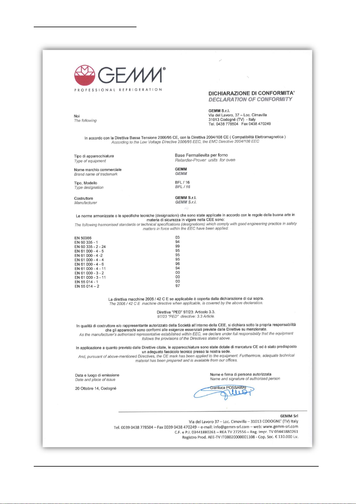
1.2 – DICHIARAZIONE DI CONFORMITA’
TALH / BFL _FL06_IT-EN Rev.01 11-2014 pag. 6
1.3 – GARANZIA
Questo simbolo contraddistingue informazioni ed avvertenze il cui mancato rispetto può danneggiare
l’apparecchiatura o compromettere la sicurezza del personale.
Questo simbolo contraddistingue informazioni ed avvertenze di carattere elettrico il cui mancato rispetto
può danneggiare l’apparecchiatura o compromettere la sicurezza del personale.
La garanzia sui componenti dell’apparecchiatura, avente decorrenza dalla data riportata sulla relativa bolla di consegna,
è come da contratto di vendita.
Non sono compresi nella garanzia danni all’apparecchiatura causati da:
- trasporto e/o movimentazione;
- errori dell’operatore;
- mancata manutenzione prevista nel presente manuale;
- guasti e/o rotture non imputabili al malfunzionamento dell’apparecchiatura;
- operazioni di manutenzione svolte da personale non qualificato;
- uso improprio.
1.4 – ASSISTENZA
Per qualsiasi necessità inerente l’uso, la manutenzione o la richiesta di parti di ricambio, l’acquirente è pregato di rivolgersi
direttamente al costruttore, specificando i dati identificativi dell’apparecchiatura riportati sulla targhetta di identificazione.
1.5 – UTILIZZO E CONSERVAZIONE DEL MANUALE
Il presente manuale ha lo scopo di fornire tutte le informazioni necessarie affinché, oltre ad un corretto utilizzo
dell’apparecchiatura, sia possibile gestire la stessa nel modo più autonomo e sicuro possibile.
Il manuale è suddiviso in capitoli, paragrafati e sotto paragrafati: la pagina dell’indice fornisce quindi un modo facile per
trovare qualunque aspetto di interesse.
Il materiale contenuto in questo documento viene fornito esclusivamente per scopi informativi ed è soggetto a modifiche
senza preavviso. Nonostante la massima attenzione riservata alla redazione del documento, la ditta costruttrice non è
responsabile per i danni derivanti da errori od omissioni e dall’utilizzo delle informazioni qui contenute.
Mantenere il presente manuale, e tutta la documentazione allegata, in buono stato, leggibile e completa di tutte le sue
parti; conservarla in prossimità dell’apparecchiatura, in un luogo accessibile e noto a tutti gli operatori.
1.5.1 – SIMBOLI UTILIZZATI NEL PRESENTE MANUALE
TALH / BFL _FL06_IT-EN Rev.01 11-2014 pag. 7

1.6 – DESCRIZIONE DEL PERSONALE
Gli operatori non devono eseguire operazioni riservate ai manutentori o ai tecnici specializzati.
Il costruttore non risponde di danni derivati dalla mancata osservanza di questo divieto.
Il manuale in oggetto è rivolto sia all’operatore che ai tecnici abilitati all’installazione ed alla manutenzione
dell’apparecchiatura.
- Operatore addetto all’uso dell’apparecchiatura: Personale specializzato in grado di operare con
l’apparecchiatura in condizioni normali attraverso l’uso dei comandi preposti. Deve inoltre essere in grado di
effettuare operazioni semplici di manutenzione ordinaria (pulizia, carico prodotto), avviamento o ripristino
dell’apparecchiatura in seguito ad un’eventuale sosta forzata.
- Tecnico specializzato elettricista: Tecnico specializzato elettricista che ha seguito i corsi di qualifica da parte
del produttore che gli consentono qualsiasi intervento sull’apparecchiatura. Il tecnico specializzato deve essere
in grado di installare l’apparecchiatura e di condurla in condizioni normali; è abilitato a tutti gli interventi di natura
elettrica e meccanica di regolazione, di manutenzione e di riparazione. E’ in grado di operare in presenza di
tensione all’interno di armadi elettrici e scatole di derivazione.
- Tecnico specializzato mulettista: Tecnico specializzato addetto alla movimentazione di materiale all’interno
dell’azienda e munito di patente per l’utilizzo di muletti.
TALH / BFL _FL06_IT-EN Rev.01 11-2014 pag. 8
2 – DESCRIZIONE DELLA MACCHINA
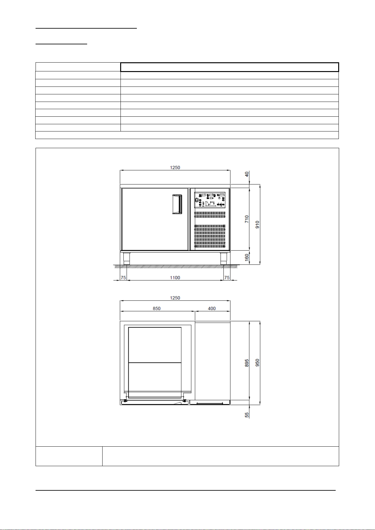
Modello
BFL - 16
Dimensioni esterne
cm
125 x 95 x 92h
Peso max
kg
125
Capacità litri
lt
400
Temperatura interna cella
°C
-2 / +35
Gas e carica
R 404 a 360gr
Potenza refrigerante
W
314
Potenza max assorbita
W
1650
Tensione di alimentazione
Volt 1x230 ~ 50 Hz
Tab. 1/a
R
Alimentazione elettrica: cavo 3x1.5 mm2 completo di spina Schuko; L=4000 mm
Electricity supply: 3x1.5 mm2 wire complete with Schuko plug; L=4000 mm
Fig. 2/a
2.1 – DATI TECNICI
TALH / BFL _FL06_IT-EN Rev.01 11-2014 pag. 9
Modello
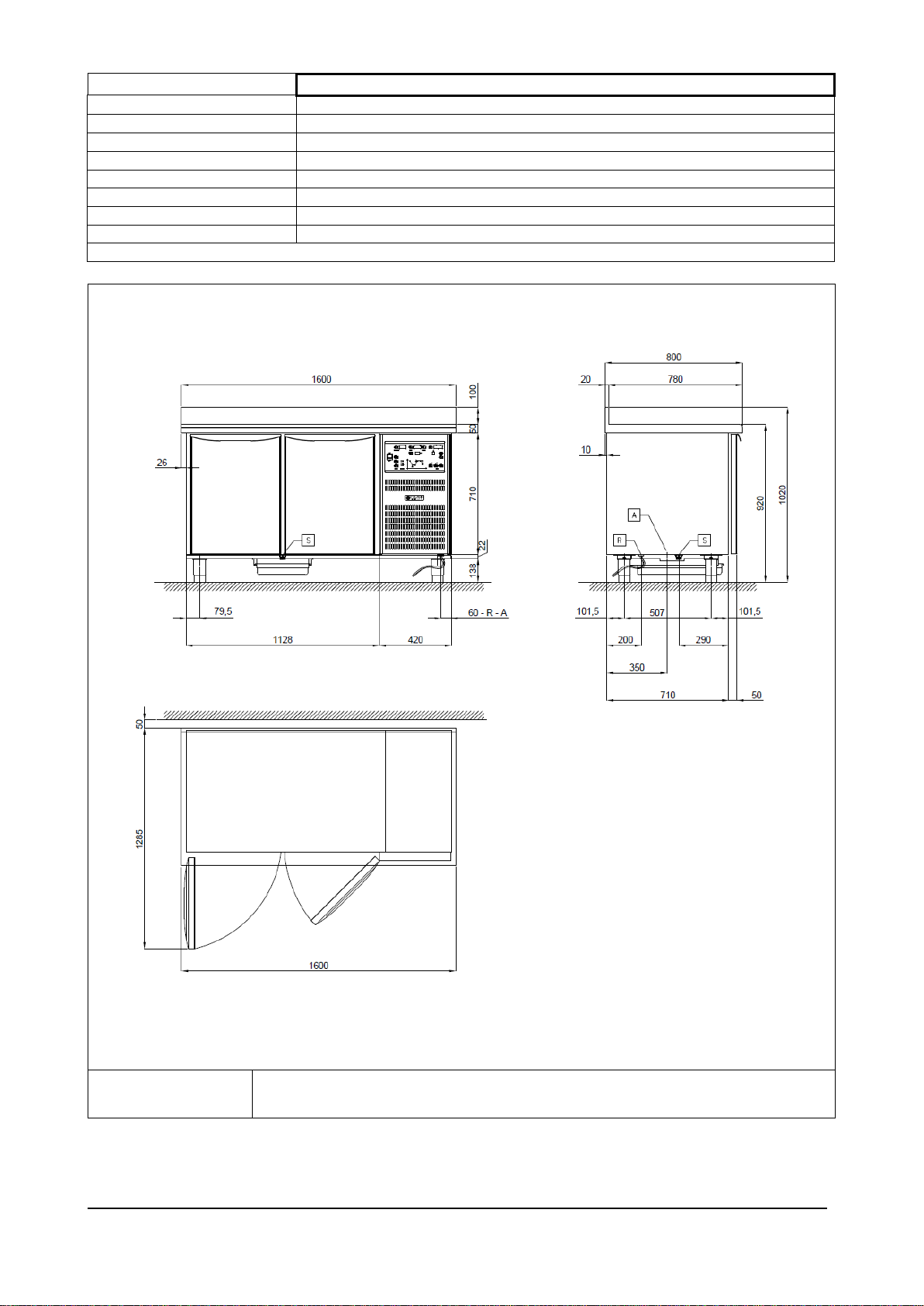
TAL - 16 / TAL/H - 16
Dimensioni esterne
cm
160 x 80 x 92h
Peso max
kg
110
Capacità litri
nr
400
Temperatura interna cella
°C
-2 / +35
Gas e carica
R 134 a 260gr
Potenza refrigerante
W
314
Potenza max assorbita
W
580
Tensione di alimentazione
Volt 1x230 ~ 50 Hz
Tab. 1/b
R
Alimentazione elettrica: cavo 3x1.5 mm2 completo di spina Schuko; L=4000 mm
Electricity supply: 3x1.5 mm2 wire complete with Schuko plug; L=4000 mm
Fig. 2/b
TALH / BFL _FL06_IT-EN Rev.01 11-2014 pag. 10
Modello
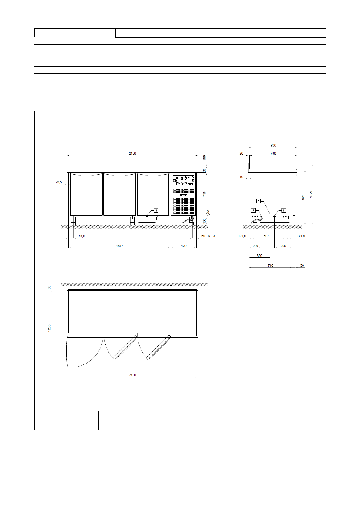
TAL - 21 / TAL/H - 21
Dimensioni esterne
cm
215 x 80 x 92h
Peso max
kg
130
Capacità litri
nr
620
Temperatura interna cella
°C
-2 / +35
Gas e carica
R 134 a 280gr
Potenza refrigerante
W
454
Potenza max assorbita
W
800
Tensione di alimentazione
Volt 1x230 ~ 50 Hz
Tab. 1/c
R
Alimentazione elettrica: cavo 3x1.5 mm2 completo di spina Schuko; L=4000 mm
Electricity supply: 3x1.5 mm2 wire complete with Schuko plug; L=4000 mm
Fig. 2/c
TALH / BFL _FL06_IT-EN Rev.01 11-2014 pag. 11
Modello
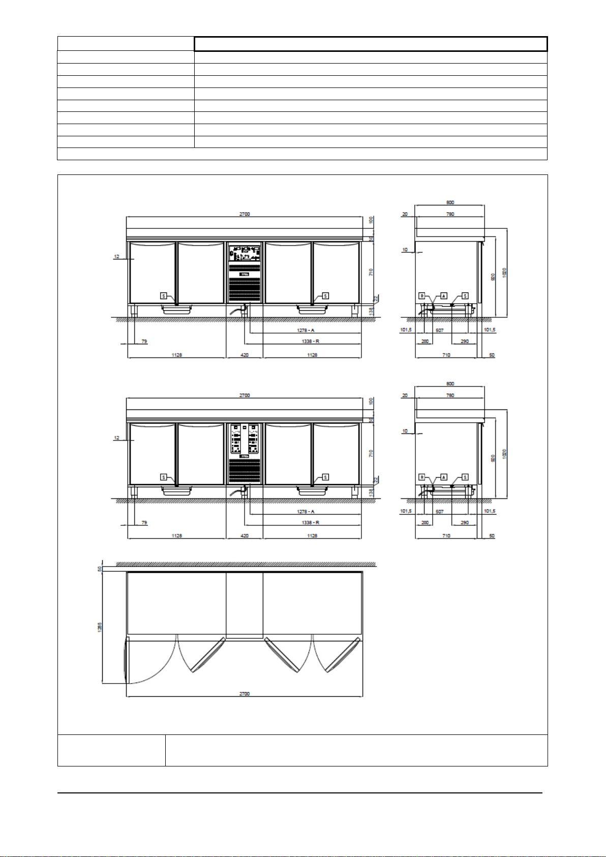
TAL - 27 / TALC – 27 // TALH – 27 / TALHC – 27
Dimensioni esterne
cm
268 x 80 x 92h
Peso max
kg
150
Capacità litri
nr
800
Temperatura interna cella
°C
-2 / +35
Gas e carica
R 134 a 340gr // R 404 a 600gr
Potenza refrigerante
W
520
Potenza max assorbita
W
1160 // 1480
Tensione di alimentazione
Volt 1x230 ~ 50 Hz
Tab. 1/d
R
Alimentazione elettrica: cavo 3x1.5 mm2 completo di spina Schuko; L=4000 mm
Electricity supply: 3x1.5 mm2 wire complete with Schuko plug; L=4000 mm
Fig. 2/d
TALH / BFL _FL06_IT-EN Rev.01 11-2014 pag. 12
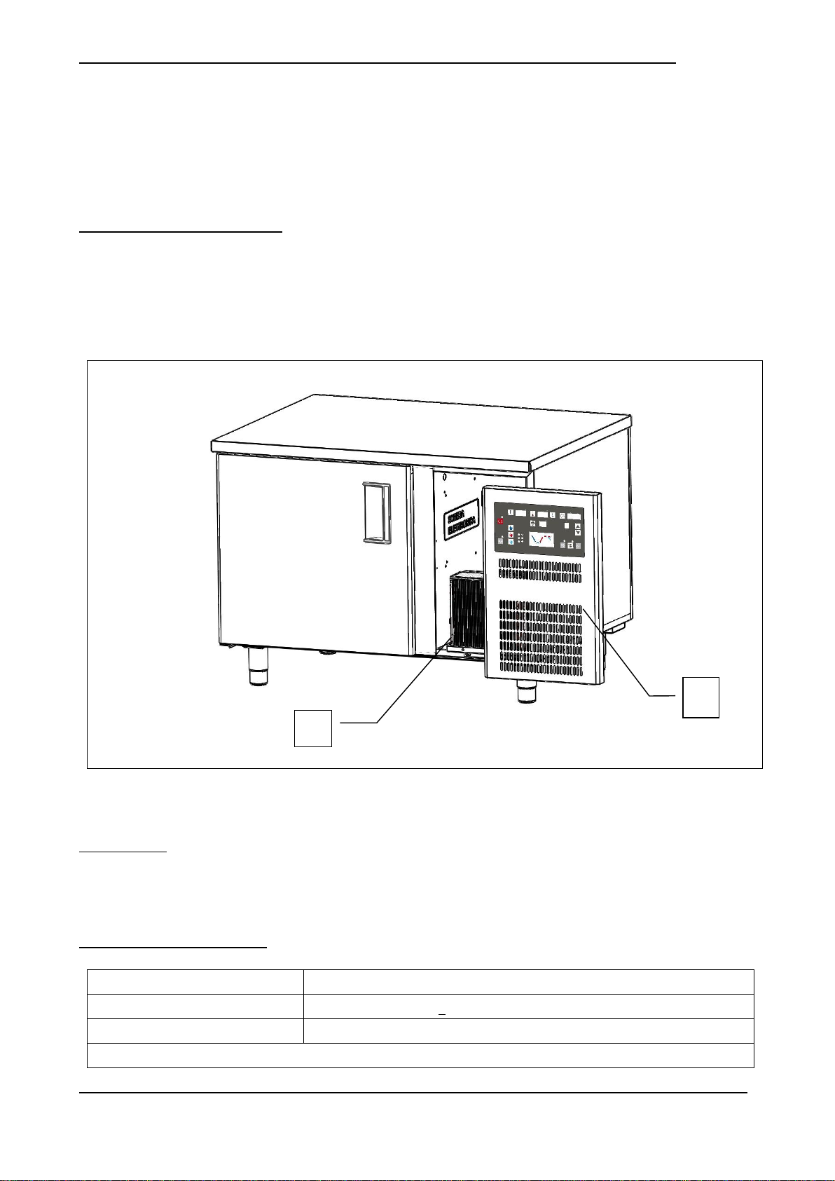
2.2 – DESCRIZIONE DEL TAVOLO FERMALIEVITAZIONE EN SERIE “PLANET” ED USO PREVISTO
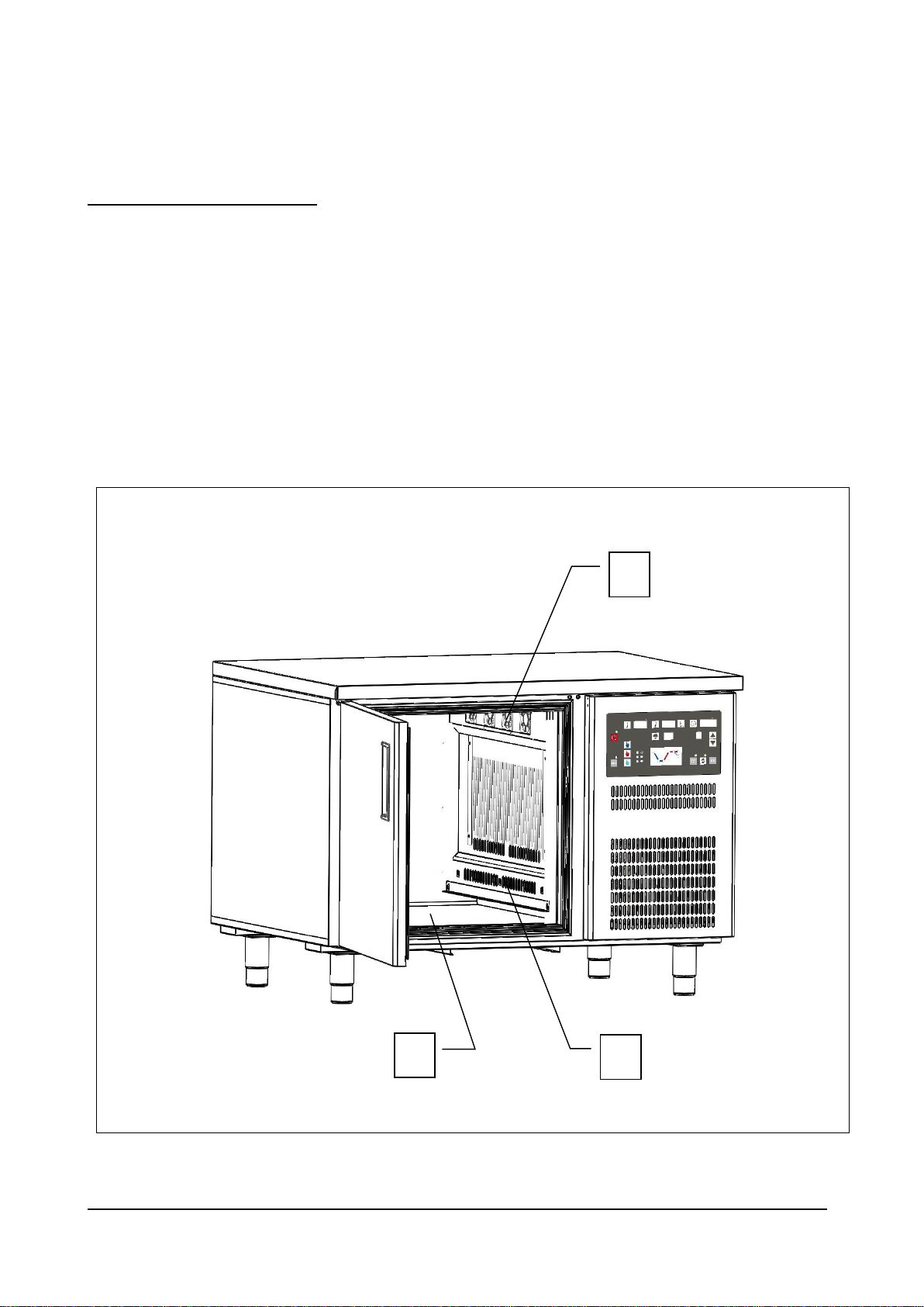
Fig. 3
Luogo di installazione
Cucine , laboratori , Ristoranti , sale drink , show-room , bar .
Umidità dell’aria relativa
< 80% con assenza di condensa
Classe climatica
“ST” + 18 °C ÷ + 38 °C
Tab. 2
1
2
I tavoli fermalievitazione EN della serie “PLANET” sono realizzati in base ai principi di essenzialità e affidabilità.
La struttura è monoscocca, realizzata sia internamente che esternamente in acciaio inox AISI 304 , con isolamento da
70 mm ottenuto mediante iniezione di resine poliuretaniche ad alta densità, esenti HCFC.
Il fondo interno cella è arrotondato per una facile pulizia, i piedini e la struttura reggigriglie sono realizzati in acciaio inox,
la porta è dotata di guarnizione magnetica ad incastro di facile sostituzione , pulizia , e riscaldata nelle versioni BT.
La refrigerazione è ventilata, con controllo tramite scheda elettronica da retropannello, sbrinamento automatico elettrico
ed evaporazione automatica dell’acqua di condensa.
2.2.1 – COMPONENTI PRINCIPALI
L’apparecchiatura è composta dai seguenti componenti:
corpo apparecchiatura;
unità refrigerante monoblocco (rif. 1, fig. 3);
pannello di controllo (rif. 2, fig. 3)
2.3 – RUMORE
L’apparecchiatura è stata progettata e realizzata in modo da ridurre al massimo il livello di potenza acustica.
Nello specifico si dichiara un livello acustico inferiore ai 60 decibel .
2.4 – CONDIZIONI AMBIENTALI
TALH / BFL _FL06_IT-EN Rev.01 11-2014 pag. 13
3. – SICUREZZA
IMPORTANTE: prima dell’utilizzo dell’apparecchiatura leggere attentamente il presente manuale d’uso
e seguire scrupolosamente le istruzioni tecniche di funzionamento e le indicazioni qui contenute.
L’operatore deve conoscere la posizione e le funzioni di tutti i dispositivi di controllo e le caratteristiche
dell’armadio refrigerato.
Il tavolo fermalievitazione è conforme alle vigenti norme di sicurezza. L’uso improprio può comunque
provocare danni a persone o cose.
All’atto dell’installazione tutto il personale operativo deve essere opportunamente istruito sui rischi di
incidente, i dispositivi di sicurezza per l’operatore, le norme generali di prevenzione degli incidenti
previste dalle direttive internazionali e dalla legge vigente nel paese di utilizzo dell’apparecchiatura.
L’avvio e l’uso dell’apparecchiatura devono essere affidati esclusivamente a personale addestrato. Il
comportamento del personale operativo deve in ogni caso rispettare scrupolosamente le norme sulle
prevenzione degli incidenti vigenti nel paese di utilizzo dell’apparecchiatura.
Non rimuovere o alterare le targhe apposte dal costruttore sull’apparecchiatura.
Il tavolo fermalievitazione non deve essere messo in funzione in caso di difetti al pannello di controllo o
parti danneggiate.
Non ostruire i condotti di aerazione superiori e/o interni dell’apparecchiatura; non riporre il prodotto a
ridosso delle griglie di ventilazione, dei condotti di aerazione, o direttamente sul fondo della cella.
Segnalare tempestivamente eventuali anomalie di funzionamento.
Usare solamente accessori raccomandati dal costruttore.
Non esporre l’apparecchiatura a pioggia o a getti d’acqua
Le operazioni di manutenzione ordinaria e straordinaria che prevedono l’apertura del quadro elettrico
oppure uno smontaggio anche parziale del tavolo fermalievitazione, devono essere effettuate solo dopo
aver interrotto l’alimentazione dell’apparecchiatura.
3.1 – AVVERTENZE GENERALI
Il produttore è sollevato da qualunque responsabilità nei seguenti casi:
mancata effettuazione della manutenzione programmata;
modifiche e/o interventi non autorizzati:
utilizzo di ricambi non originali;
mancato o parziale rispetto di quanto riportato nel presente manuale;
uso improprio dell’apparecchiatura.
TALH / BFL _FL06_IT-EN Rev.01 11-2014 pag. 14
Qualunque manomissione o sostituzione non autorizzata di una o più parti o componenti dell’apparecchiatura,
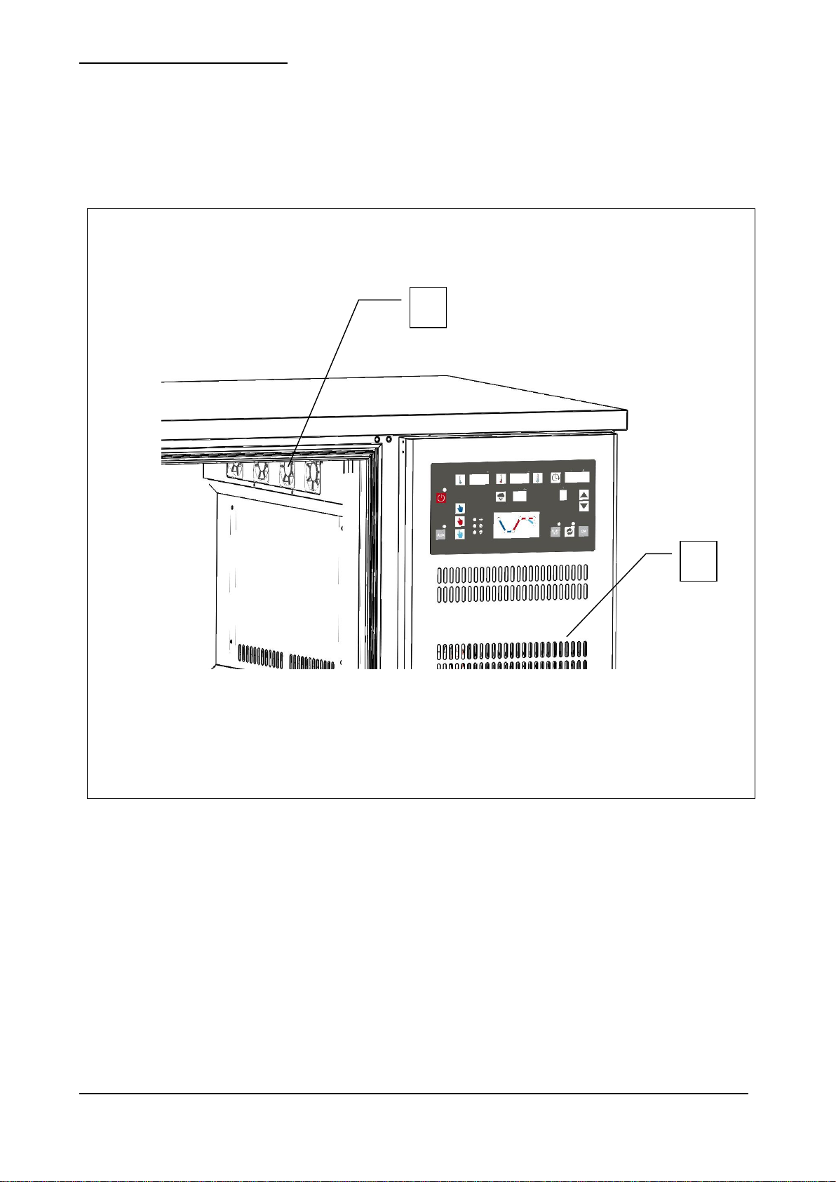
Fig. 4
3
1
2
l’utilizzo di accessori e materiale di consumo diversi dagli originali, possono rappresentare un rischio di incidente
e sollevano il costruttore da qualunque responsabilità civile o penale.
In caso di dubbio relativamente al funzionamento dell’apparecchiatura, non usarla e contattare il costruttore.
3.2 – CONTROINDICAZIONI D’USO
Il Tavolo fermalievitazione EN serie “PLANET” non deve essere utilizzato:
per utilizzi diversi da quelli riportati nel paragrafo 2.2 “Descrizione del tavolo fermalievitazione ed uso previsto”;
con sistemi di sicurezza non funzionanti;
dopo un’installazione non eseguita correttamente;
da personale non addestrato;
con interventi di manutenzione non eseguiti o eseguiti in modo scorretto;
con utilizzo di ricambi non originali;
con cavo di alimentazione e/o presa elettrica danneggiati;
con condotti di aerazione (rif. 1, fig. 4) ostruiti;
con prodotti alimentari vari (cibi e bevande) posti a ridosso delle griglie di ventilazione interne (rif. 2, fig. 4), o
direttamente sul fondo della cella (rif. 3, fig. 4).
TALH / BFL _FL06_IT-EN Rev.01 11-2014 pag. 15
3.3 – DISPOSITIVI DI PROTEZIONE
Fig. 5
1
2
La protezione del personale esposto ai rischi, dovuti agli elementi mobili pericolosi, è garantita dalla presenza di opportuni
dispositivi presenti sull’apparecchiatura:
Pannello frontale a copertura dell’unità condensatrice (rif. 1, fig. 5);
Griglie interne a copertura delle ventole evaporatore (rif. 2, fig. 5).
TALH / BFL _FL06_IT-EN Rev.01 11-2014 pag. 16
3.4 – FUNZIONI DI ARRESTO
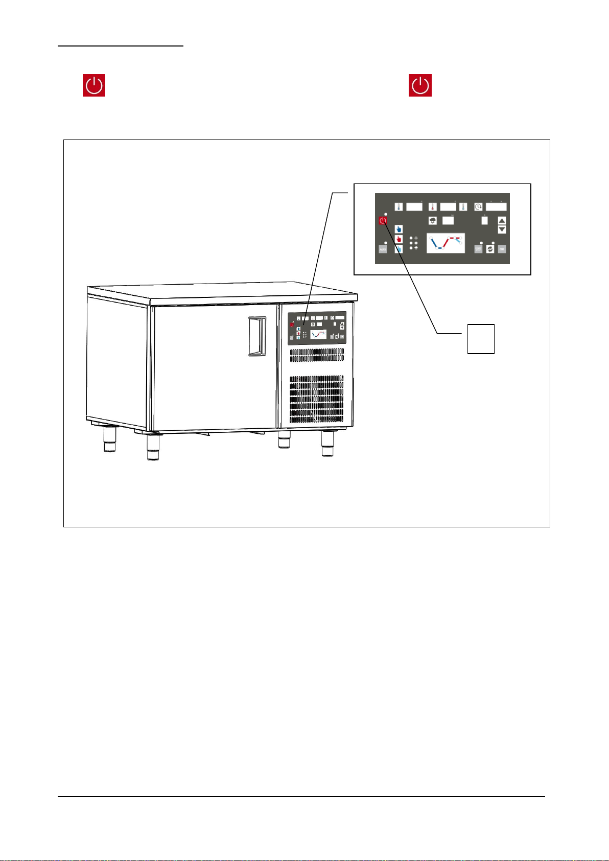
Fig. 6
1
L' apparecchiatura nel suo complesso è controllata da una scheda elettronica. La funzione di arresto è rappresentata dal
tasto (rif. 1 fig. 6). In qualsiasi stato si trovi la macchina , la pressione del tasto mette la scheda in OFF.
TALH / BFL _FL06_IT-EN Rev.01 11-2014 pag. 17
4 – TRASPORTO E MOVIMENTAZIONE
L’apparecchiatura non deve essere assolutamente capovolta.
L’imballo deve essere ben posizionato sul pianale del mezzo di trasporto e bloccato attraverso
l’utilizzo di funi appropriate.
E’ necessario prestare la massima attenzione durante tutte le fasi di sollevamento e
posizionamento dell’armadio, in modo da evitare danni, anche gravi, a persone o cose. Il
costruttore non si assume alcuna responsabilità per il mancato rispetto delle indicazioni
riportate per il sollevamento e il trasporto dell’armadio.
Durante la fase di trasporto la temperatura ambientale non deve mai scendere al di sotto dei 4°C.
Prestare attenzione durante le fasi di sollevamento e movimentazione dell’armadio; esiste il
pericolo di lesioni anche mortali contro il carico in movimento.
Tutte le operazioni di movimentazione e sollevamento devono essere effettuate con la massima
cautela, controllando che tutto il personale sia rigorosamente a distanza di sicurezza, e che
nessuno sosti sotto carichi sospesi, fermi o in movimento.
Prima di iniziare l’operazione, controllare tutta l’area di movimentazione dell’apparecchiatura,
in modo da rilevare l’eventuale presenza di punti pericolosi.
Durante la fase di trasporto la temperatura ambientale non dove mai scendere al di sotto del 4°C.
4.1 – TRASPORTO DEL TAVOLO FERMALIEVITAZIONE
In funzione della tipologia e delle dimensioni e pesi sono stati utilizzati imballi adeguati a garantire l’integrità e la
conservazione durante il trasporto fino alla consegna all’acquirente.
Il tavolo fermalievitazione deve essere posizionato e mantenuto in piedi su bancale avvolto dal proprio cartone per tutta la
durata del trasporto.
Il tavolo fermalievitazione viene fornito al trasportatore pronto per lo spostamento.
Il materiale d’imballo, una volta disimballato il tavolo fermalievitazione, dovrà essere eliminato e/o riutilizzato secondo le
norme vigenti del Paese di destinazione dell’apparecchiatura.
4.2. – MOVIMENTAZIONE DEL TAVOLO FERMALIEVITAZIONE IMBALLATO
TALH / BFL _FL06_IT-EN Rev.01 11-2014 pag. 18
PERSONALE AUTORIZZATO
Modello
BFL - 16
Dimensione
cm
125 x 95 x 90h
Peso
Kg
130
Modello
TAL/H - 16
TAL/H - 21
TAL/H - 27 / TAL/H - 27 C
Dimensione
cm
160 x 76 x 90h
215 x 76 x 90h
268 x 76 x 60h
Peso
Kg
110
130
150
L’impiego di attrezzature non adeguate può comportare incidenti al personale impiegato
nell’operazione e/o danni all’apparecchiatura.
Il costruttore non si assume alcuna responsabilità per l’uso improprio e non conforme di
apparecchi per il sollevamento, il trasporto e la movimentazione.
Tecnico specializzato mulettista.
Mezzi di protezione individuali:
- scarpe antinfortunistiche;
- guanti antinfortunistici.
Il personale addetto a tali operazioni non deve utilizzare anelli, orologi da polso, gioielli, capi di vestiario slacciati o sciolti,
quali ad esempio cravatte, indumenti strappati, sciarpe, giacche sbottonate o bluse con chiusure a lampo aperte ecc… In
generale il personale deve usare capi ad uso antinfortunistico.
4.2.1 – PESO E INGOMBRO DEL TAVOLO FERMALIEVITAZIONE
4.2.2 – MEZZI NECESSARI
- Per il sollevamento dell’apparecchiatura deve essere utilizzato un muletto con portata minima adeguata.
TALH / BFL _FL06_IT-EN Rev.01 11-2014 pag. 19

5 – INSTALLAZIONE
Prestare la massima cautela nel maneggiare l’apparecchiatura, in modo da evitare danni alle cose o alle
persone.
L’apparecchiatura non deve essere messa in funzione in caso di difetti al pannello di controllo o parti
danneggiate.
Verificare che l’imballo non sia stato danneggiato durante il trasporto.
L’impiego di attrezzature non adeguate può comportare incidenti al personale impiegato
nell’operazione e/o danni all’apparecchiatura.
Il costruttore non si assume alcuna responsabilità per l’uso improprio e non conforme di
apparecchi per il sollevamento, il trasporto e la movimentazione.
PERSONALE AUTORIZZATO
Tecnico specializzato elettricista.
Mezzi di protezione individuali:
scarpe antinfortunistiche;
guanti antinfortunistici.
Il personale addetto a tali operazioni non deve utilizzare anelli, orologi da polso, gioielli, capi di vestiario slacciati o sciolti,
quali ad esempio cravatte, indumenti strappati, sciarpe, giacche sbottonate o bluse con chiusure a lampo aperte ecc… In
generale il personale deve usare capi ad uso antinfortunistico.
5.1 – PREDISPOSIZIONE ALL’INSTALLAZIONE
Per l’installazione occorre predisporre un’area di manovra adeguata alle dimensioni dell’apparecchiatura (vedi fig. 2) e dei
mezzi di sollevamento prescelti.
Il luogo di installazione dovrà essere predisposto di tutta l’impiantistica di collegamento necessaria alla messa in funzione
dell’apparecchiatura.
Il luogo scelto per l’installazione deve avere requisiti idonei a permettere l’utilizzazione dell’apparecch iatura in condizioni
di sicurezza. La zona deve essere tale da garantire una buona base di appoggio, con pavimentazione solida, livellata e
con finitura tale da garantire un’adeguata e sicura operatività del personale.
Il luogo d’installazione deve presentare un’illuminazione, naturale e/o artificiale, adeguata alle operazioni da svolgere (in
base alle norme specifiche).
5.2 – DISIMBALLAGGIO
5.2.1 – MEZZI NECESSARI
Per il sollevamento dell’apparecchiatura deve essere utilizzato un muletto o un’attrezzatura equivalente.
TALH / BFL _FL06_IT-EN Rev.01 11-2014 pag. 20

5.2.2 – PROCEDURA DI DISIMBALLAGGIO
Tutte le operazioni di movimentazione e disimballaggio devono essere effettuate con la massima
cautela, controllando che tutto il personale sia rigorosamente a distanza di sicurezza, e che
nessuno sosti sotto carichi sospesi, fermi o in movimento.
DOPO LA FASE DI INSTALLAZIONE DELL’APPARECCHIATURA, ATTENDERE ALMENO DUE
ORE PRIMA DI PROCEDERE ALL’ACCENSIONE DI ESSA.
L’impiego di attrezzature non adeguate può comportare incidenti al personale impiegato
nell’operazione e/o danni all’apparecchiatura.
Il costruttore non si assume alcuna responsabilità per l’uso improprio e non conforme di
apparecchi per il sollevamento, il trasporto e la movimentazione.
Tutte le operazioni di movimentazione e disimballaggio devono essere effettuate con la massima
cautela, controllando che tutto il personale sia rigorosamente a distanza di sicurezza, e che
nessuno sosti sotto carichi sospesi, fermi o in movimento.
Per disimballare l’apparecchiatura è sufficiente togliere il cartone posto attorno ad essa. Procedere, successivamente, a
far scendere l’apparecchiatura dal bancale, sollevandola attraverso l’utilizzo di un apposito muletto; le forche del muletto
vanno poste sotto all’apparecchiatura.
5.3 – MOVIMENTAZIONE DEL TAVOLO FERMALIEVITAZIONE
5.3.1 – MEZZI NECESSARI
Vedi paragrafo 5.2.1.
5.3.2 – PROCEDURA DI MOVIMENTAZIONE DEL TAVOLO DISIMBALLATO
Per movimentare il tavolo, procedere al sollevamento attraverso l’utilizzo di un apposito muletto; le forche del muletto
vanno poste sotto all’apparecchiatura.
5.4 – MONTAGGIO DELL’ARMADIO
Il cliente riceve il tavolo fermalievitazione, montato in tutte le sue parti.
TALH / BFL _FL06_IT-EN Rev.01 11-2014 pag. 21

6 - ISTRUZIONI
L' apparecchiatura nel suo complesso è controllata da una scheda elettronica che viene alimentata agendo sull' interruttore
generale ON/OFF.
Utilizzando i comandi posti sul pannello ed aiutandosi con i display luminosi è possibile attivare dei funzionamenti manuali
oppure automatici.
6.1 - VERIFICHE PRELIMINARI
Alimentare la scheda portando l'interruttore su ON. Con l’ apparecchiatura in pausa è possibile eseguire le impostazioni di
cui sotto (qualora l’ apparecchiatura fosse attiva premere Start (G) prima di procedere).
Sul display (E) compare il Giorno indicato come: 1=lunedì, 2=martedì, …7=domenica.
Sul display (D) compare l'Ora corrente indicata in ore e minuti.
Tenendo premuto per 3 secondi Orologio (H) inizierà a lampeggiare il Giorno corrente (E): tramite le frecce ALTO e
BASSO è possibile impostare il dato corretto.
Premendo ulteriormente Orologio (H) si andranno ad impostare in maniera analoga l' Ora e i Minuti (D).
6.2 - FUNZIONAMENTO MANUALE
La modalità manuale prevede tre fasi indipendenti e di durata infinita:
- conservazione
- lievitazione
- mantenimento
Durante il funzionamento l’attivazione di ciascuna fase è rappresentata graficamente sul diagramma (F).
Con l' interruttore manuale su ON i display (D) e (E) visualizzano rispettivamente l' Ora ed il Giorno correnti.
Premendo Start (G) il display (D) visualizza la modalità. Con l’utilizzo delle frecce ALTO e BASSO passare da “AUTO” a
“MAN” e confermare con OK.
Per 10 secondi il display (A) lampeggia, dopo di che viene avviata la fase di conservazione manuale.
E’ possibile passare alle fasi di lievitazione e mantenimento premendo rispettivamente (P) e (Q).
Fase di Conservazione
Durante questa fase sul display (A) appare la temperatura della cella e rimangono invece spenti i display (B) e (C).
Premendo Termometro (I) è possibile visualizzare il set-point di lavoro. Il valore appare lampeggiando e può essere
accettato con OK oppure modificato con le frecce ALTO e BASSO prima di essere confermato con OK. (Non premendo
OK si avrà la conferma automatica per time-out). I primi tre led sono accesi (linea blu su grafico (F)).
(Per limiti impostazione vedi par. 1.6)
Fase di Lievitazione
Durante questa fase sul display (B) appare la temperatura della cella, sul display (C) l' umidità % misurata dalla sonda:
rimane invece spento il display (A). Premendo Termometro (L) è possibile visualizzare il set-point di temperatura della
cella. Il valore appare lampeggiando e può essere accettato con OK oppure modificato con le frecce ALTO e BASSO prima
di essere confermato con OK. (Non premendo OK si avrà la conferma automatica per time-out).
Analogamente premendo Umidità (N) è possibile visualizzare/impostare il set-point di umidità. Il quarto, il quinto ed il sesto
led sono accesi (linea rossa sul grafico (F)).
(Per limiti impostazione vedi par. 1.6)
Fase di Mantenimento
Durante questa fase sul display (B) appare la temperatura della cella; rimangono invece spenti i display (E) e (C).
Premendo Termometro (M) è possibile visualizzare il set-point di temperatura della cella. Il valore appare lampeggiando e
può essere accettato con OK oppure modificato con le frecce ALTO e BASSO prima di essere confermato con OK. (Non
premendo OK si avrà la conferma automatica per time-out).
Gli ultimi tre led sono accesi (linea rossa su grafico (F)).
(Per limiti impostazione vedi par. 1.6)
TALH / BFL _FL06_IT-EN Rev.01 11-2014 pag. 22

6.3 - FUNZIONAMENTO AUTOMATICO
Descrizione programma
Set
-point temperatura di Raffredda
mento
(display (A))
Durata
in ore e minuti della fase di
raffreddamento (display (D))
Set
-point temperatura conservazione
(display (A))
Set
-point temperatura rinvenimento
(display (B))
Set
-point umidità % durante rinvenimento
(display (C))
Durata
in ore e minuti della fase di rinvenimento
(display (D))
Set
-point temperatura lievitazione
(display (B))
Set
-point umidità % durante la lievitazione
(display (C))
Durata
in ore e minuti della fase di lievitazione
(display (D))
Set
-point temperatura
mantenimento
(display (B))
Giorno settimana
Fine Lievitazione
(corrispondente all’inizio mantenimento)
(display (E))
Orario
in ore e minuti
Fine lievitazione
(corrispondente all’inizio mantenimento)
(display (D))
Valore impostato
(spazi riservati per operatore)
La modalità automatica prevede la possibilità di impostare e memorizzare 10 diversi cicli ciascuno con durata massima di
7 giorni.
Le fasi distinguibili all’interno di un ciclo automatico sono:
- raffreddamento
- conservazione
- rinvenimento / risveglio
- lievitazione
- mantenimento
Durante il funzionamento l’attivazione di ciascuna fase è rappresentata graficamente sul diagramma (F).
Con l’interruttore manuale su ON i display (D) e (E) visualizzano rispettivamente l’ora ed il giorno correnti.
Premendo start (G) il display (D) visualizza la modalità. Con l’utilizzo delle frecce ALTO e BASSO passare da “MAN” ad
“AUTO” e confermare con OK.
Viene subito proposto PR1 sul display (D). Tramite le freccia ALTO e BASSO è possibile scorrere fino a PR10 tutti i cicli
impostabili, selezionando quello desiderato.
A questo punto se non si interviene entro 20 secondi il ciclo proposto sul display (D) viene attivato.
6.4 - IMPOSTAZIONE CICLO
Il ciclo proposto sul display (D) va controllato/impostato prima di essere confermato.
Per fare questo premere il tasto ciclo (R), impostare il valore desiderato attraverso l’utilizzo delle frecce ALTO e BASSO
e premere nuovamente ciclo (R) per confermare e passare al parametro successivo.
I parametri sono:
TALH / BFL _FL06_IT-EN Rev.01 11-2014 pag. 23

Descrizione programma
Set
-point temperatura di Raffreddamento
(display (A))
Durata
in ore e minuti della fase di raffreddamento
(display (D))
Set
-point temperatura conservazione
(display (A))
Set
-point temperatura rinvenimento
(display (B))
Set
-point umidità % durante rinvenimento
(display (C))
Durata
in ore e minuti della fase di rinvenimento
(display (D))
Set
-point temperatura lievitazione
(display (B))
Set
-point umidità % durante la lievitazione
(display (C))
Durata
in ore e minuti della fase di lievitazione
(display (D))
Set
-point temperatura mantenimento
(display (B))
Giorno settimana
Fine Lievitazione
(corrispondente all’inizio mantenimento)
(disp
lay (E))
Orario
in ore e minuti
Fine lievitazione
(corrispondente all’inizio mantenimento)
(display (D))
Valore impostato
(spazi riservati per operatore)
PR1
PR2
PR3
PR4
PR5
PR6
PR7
PR8
PR9
PR10
Così fatto per avviare il ciclo automatico appena impostato è necessario premere OK, viceversa si uscirà dalla
programmazione per time-out senza avviare il ciclo.
TALH / BFL _FL06_IT-EN Rev.01 11-2014 pag. 24

6.5 – CICLO AUTOMATICO
Durante il funzionamento automatico i led relativi al pulsante start (G) e ciclo (R) rimangono accesi. I led corrispondenti a
compressore, resistenze ed iniezione vapore si accendono al funzionare del componente rappresentato. I display (E) e
(D) mostrano rispettivamente il giorno e l’ora in cui avrà termine la fase di lievitazione.
Fase di Raffreddamento
Durante il raffreddamento il primo led sul diagramma (F) è acceso mentre il secondo lampeggia fino al raggiungimento del
set point oppure per tutta la durata della fase se non dovesse essere raggiunto il set-point.
La temperatura in cella è visualizzata sul display (A).
Fase Conservazione
Durante la conservazione i primi due led sul diagramma(F) sono accesi mentre il terzo lampeggia.
La durata di questa fase è il risultato della differenza fra la durata del ciclo automatico intero meno la durata della
lievitazione, del risveglio e del raffreddamento.
La temperatura in cella è visualizzata sul display (A).
Fase Risveglio
Durante il risveglio i primi tre led sono accesi sul diagramma (F) mentre il quarto lampeggia fino al raggiungimento del setpoint oppure per tutta la durata della fase, se non dovesse essere raggiunto il set-point.
La temperatura e l’umidità relativa % presenti in cella sono visualizzate rispettivamente sui display (B) e (C).
Fase di Lievitazione
Durante la lievitazione i primi quattro led sono accesi sul diagramma (F), mentre il quinto lampeggia fino al raggiungimento
del set-point oppure per tutta la durata della fase, se non dovesse essere raggiunto il set-piont.
La temperatura e l’umidità relativa % presenti in cella sono visualizzate rispettivamente sui display (B) e (C).
La fine della lievitazione è segnalata acusticamente. Il quinto led smette di lampeggiare e rimane sempre acceso.
Fase di Mantenimento
Il mantenimento dura finchè il ciclo automatico non viene terminato con il tasto START/STOP.
Sul diagramma (F) i primi cinque led sono accesi. Se la temperatura di mantenimento dovesse essere superiore a quella
di lievitazione sarà acceso anche il sesto led sulla linea rossa.
Viceversa se la temperatura di mantenimento dovesse essere inferiore a quella di lievitazione sarà acceso il sesto led
sulla linea azzurra.
La temperatura presente in cella è visualizzata sul display (B).
6.6 - LIMITI IMPOSTAZIONI
- Set-point temperatura Raffreddamento: -2 ÷ +14°C (oppure –18 ÷ +5°C su armadio bassa temperatura). Valore
impostato in azienda 0°C.
- Set-point temperatura di Lievitazione: +14 ÷ +35°C (oppure +5 ÷ +35 su armadio bassa temperatura).
Valore impostato in azienda 25°C.
- Set-point temperatura di Mantenimento: -2 ÷ +35°C (oppure –18 ÷ +35°C su armadio bassa temperatura). Valore
impostato in azienda 10°C.
- Set-point umidità: 0 (disattivazione controllo) ÷ 95%. Valore Impostato in azienda 50%.
TALH / BFL _FL06_IT-EN Rev.01 11-2014 pag. 25

6.7 - ALLARMI
L’apertura della porta blocca la ventilazione e l’immissione vapore. Se prolungata, viene attivata la segnalazione acustica.
I guasti e i funzionamenti anomali sono evidenziati dagli allarmi, di cui segue, sul display (A) e sono accompagnati da una
segnalazione acustica.
- AL1: errore sonda cella. Tutte le regolazioni vengono bloccate. E' un guasto che richiede la verifica e successiva
sostituzione della sonda PTC all'interno della cella. Il riarmo è manuale e avviene premendo start (G).
- AL2: allarme termostato di sicurezza (dove presente). Segnala una sovra-temperatura all'interno della cella e
coincide con l'intervento del termostato di sicurezza che disattiva di fatto l'alimentazione delle resistenze fino al
riarmo automatico del termostato stesso. La ripresa del ciclo è manuale ed avviene premendo Start (G).
- AL3: errore sonda di sbrinamento. Le regolazioni vengono bloccate. E’ un guasto che richiede la verifica e
successiva sostituzione della sonda PTC infilata sull’evaporatore.
- AL6: Possibile corruzione dati orologio. L’eventuale ciclo in corso viene bloccato. Non è garantito il corretto
funzionamento dell’orologio durante le fasi in cui la scheda rimane non alimentata. Il riarmo è manuale ed avviene
premendo il tasto (H) per 5 secondi.
TALH / BFL _FL06_IT-EN Rev.01 11-2014 pag. 26

7. - TABELLA PARAMETRI
Par. n°
Descrizione
Unità
Misura
Valore impostato
TAL / H
BFL - 16
1
0=Celsius
1=Farhenheit
- - - 0 0
2
Min set-point impostabile Raffreddamento
°C
-2
-2
3
Max set-point impostabile Raffreddamento
°C
+14
+14
4 Min set-point impostabile Lievitazione
°C
+14
+14
5
Max set-point impostabile Lievitazione
°C
+35
+35
6 Min set-point impostabile Mantenimento
°C
-2
-2
7 Max set-point impostabile Mantenimento
°C
+35
+35
8 Isteresi di regolazione
°C
+3
+3
9
Differenziale intervento contro-fase
°C
+1
+1
10
Tempo spunto per ventola
Sec. 5 5
11
Scala parzializzazione ventole
- - -
600
600
12
Ritardo fra due ON compressore
Sec.
300
300
13
Ritardo fra OFF e ON compressore
Sec.
270
270
14
Tempo inibizione compressore da reset
Sec.
10
10
15
Polarità porta:
0=nessuna tensione applicata (porta chiusa)
1=tensione applicata (porta chiusa)
- - - 1 1
16
Ritardo Buzzer da porta aperta
Sec.
20
20
17
Polarità termostato sicurezza:
0=a contatto aperto attiva allarme
1=a contatto chiuso attiva allarme
- - - 0 0
18
Time-out programmazione manuale
Sec.
30
30
19
Time-out programmazione automatica
Sec.
40
40
20
Tempo tra due sbrinamenti successivi
.h. 8 6
21
Tipo sbrinamento:
0=resistenza
1=gas caldo
2=aria
- - - 0 0
22
Temperatura di fine sbrinamento
°C 8 8
23
Durata massima sbrinamento
.min.
30
30
24
Tempo sgocciolamento
.min. 5 5
25
Base tempi:
0=ore/minuti
1=minuti/secondi
- - - 0 0
26
Abilita blocco ventole in sbrinamento
0=abilita
1=blocco
- - - 1 1
27
Durata blocco ventole dopo sgocciolamento
.min. 0 0
28
Scelta fasi in cui lo sbrinamento è abilitato:
0=nessuna fase
1=raffreddamento
2=raffreddamento/mantenimento
3=mantenimento
- - - 2 2
29
Omissis
Sec. 0 0
30
Abilitazione sonda evaporatore:
0=disabilitata
1=abilitata
- - - 1 1
31
Limite inferiore Temperatura Cella per iniezione
vapore
°C
+10
+10
32
Abilita controllo umidità da resistenze:
0=umidità abilitata sempre
1=umidità abilitata con resistenze accese
- - - 0 0
33
Scelta configurazione:
0=umidità a step
1=no umidità/umidità controllata
- - - 1 1
34
Par.33=1 Differenziale regolazione umidità
% 0 5
35
Tempo ON iniezione vapore P1
Sec.
20
0
36
Tempo ON iniezione vapore P2
Sec.
30
0
37
Tempo ON iniezione vapore P3
Sec.
40
0
38
Tempo ON iniezione vapore P4
Sec.
50
0
39
Tempo ON iniezione vapore P5
Sec.
60
0
Per entrare in programmazione premere contemporaneamente freccia ALTO e BASSO per almeno 4 secondi. A questo
punto sul display (B) compare il numero del parametro e sul display (D) il suo valore. Utilizzare (L) e (N) per passare da
un parametro all' altro e le Frecce ALTO e BASSO per modificarne il valore.
TALH / BFL _FL06_IT-EN Rev.01 11-2014 pag. 27

40
Durata ciclo ON+OFF iniezione vapore in modo
automatico
Sec.
240
240
41
Stato ventole durante immissione vapore
0=ventole ferme
1=ventole accese
- - - 1 1
42
Limite inferiore sonda umidità
%
0 *
0 *
43
Limite superiore sonda umidità
%
100 *
100 *
44
Scelta dopo power-down
- - - 1 1
45
Calibrazione sonda cella
°C 0 -1
46
Calibrazione sonda evaporatore
°C 0 0
47
Abilitazione ingresso porta
0=disabilitato
1=abilitato
- - - 0 1
48
Abilitazione presenza “Controllo Umidità”
0=disabilitato
1=abilitato
- - - 1 1
49
Numero passi di regolazione in Risveglio
- - - 3 3
50
Numero passi di regolazione in Lievitazione
- - - 1 1
* Indicare rispettivamente la percentuale r.H. corrispondente a 4mA (par. 42) e corrispondente a 20mA (par.43).
8. - ALTRI DATI SIGNIFICATIVI
8.1 - Compressore
Il compressore nel suo funzionamento deve rispettare i tempi stabiliti con par. 12, par. 13 e par. 14 (rispettivamente:
ritardo fra due ON compressore, ritardo fra OFF e ON compressore e tempo di inibizione del compressore dopo il reset).
Durante le fasi di Raffreddamento e Mantenimento il compressore si ferma in corrispondenza del set-point di temperatura
impostato.
Durante la fase di Fermentazione può agire in contro-fase nelle seguenti modalità:
se la temperatura della cella è maggiore della somma di set-point + par. 8 + par. 9 e fino al raggiungimento di una
temperatura pari a set-point + par. 9.
8.2 - Resistenze di riscaldamento
Durante la fase di Lievitazione le resistenze si fermano in corrispondenza del set-point di temperatura impostato.
Durante la fase di Raffreddamento sono completamente escluse.
8.3 - Resistenze anti-ghiaccio
La resistenza anti-ghiaccio all’interno della vaschetta raccolta acqua condensa (dove presente) funziona sempre in
maniera ininterrotta tranne nelle fasi di risveglio e lievitazione.
8.4 - Ventilatori evaporatore
Le ventole funzionano a piena potenza quando sono attivi il compressore o le resistenze, viceversa funzionano
parzializzate secondo il par. 11 (scala parzializzazione ventole). Durante lo sbrinamento vengono completamente
disattivate. Si fermano all’apertura della porta.
8.5 - Termostato di sicurezza
Il termostato di sicurezza a temperatura con bulbo interno cella, interviene ad una temperatura di 145±3° C e si riarma in
maniera esclusivamente manuale solo al di sotto della temperatura di 105±3° C.
8.6 - Power-down
L’apparecchiatura è dotata di un sistema di controllo contro le interruzioni di alimentazione elettrica tale che: un eventuale
ciclo viene sempre ripreso.
TALH / BFL _FL06_IT-EN Rev.01 11-2014 pag. 28

8.7 – Pannello elettronico e caratteristiche
A) Temperatura fase Raffreddamento
B) Temperatura fasi Lievitazione-Mantenimento
C) Umidità fasi Lievitazione
D) Orologio
E) Calendario giorni
F) Rappresentazione grafica delle fasi
G) Start / Stop
H) Impostazioni Orologio-Calendario
I) Set Point temperatura fase Raffreddamento
manuale
L) Set Point temperature fase Lievitazione
manuale
M) Set Point temperature fase Mantenimento
manuale
N) Set Point umidità fasi Lievitazione manuale
O) Comando manuale fase Raffreddamento
P) Comando manuale fase Lievitazione
Q) Comando manuale fase Mantenimento
R) Impostazione ciclo automatico
A
B
D H F
G I L
M
C
R
N Q P
O
E
TALH / BFL _FL06_IT-EN Rev.01 11-2014 pag. 29

9 – SMONTAGGIO
Per qualsiasi attività di smontaggio dell’apparecchiatura contattare l’installatore.
PRESTARE ATTENZIONE CHE L’APPARECCHIATURA CONTIENE DEL GAS REFRIGERANTE
IL CUI CONTROLLO E RECUPERO DOVRA’ ESSERE TRATTATO SECONDO QUANTO
PREVISTO DALLA NORMATIVE VIGENTI NEL PAESE DI SMALTIMENTO.
Per qualsiasi attività di smontaggio dell’apparecchiatura contattare l’installatore.
10 – SMANTELLAMENTO
10.1 – MODALITA’ DI SMANTELLAMENTO
STATO DELL’APPARECCHIATURA
- scheda elettronica posizione OFF sul display;
- spina di alimentazione scollegata della rete elettrica.
MODALITA’
L’apparecchiatura è costruita con materiali ferrosi, componenti elettronici e materie plastiche. Nel caso sia necessario
procedere alla rottamazione, separare i diversi componenti in base al materiale di cui sono costituiti, in modo da
semplificare lo smaltimento differenziato o un’eventuale riutilizzo delle parti. L’apparecchiatura deve essere smaltita in
modo differenziato dai rifiuti urbani.
Quando l’apparecchiatura è demolita non vi sono particolari istruzioni da eseguire. Affidare la rottamazione ad apposite
imprese di smaltimento o, nei casi previsti dalla legge, riconsegnarla al rivenditore (vedi anche “Informazione agli utenti
relativa allo smaltimento dei rifiuti nell’ambito dell’Unione Europea” di seguito riportata).
Per la rottamazione fare sempre riferimento alle leggi vigenti nel paese di utilizzo (vedi anche “Informazione agli utenti
relativa allo smaltimento dei rifiuti nell’ambito dell’Unione Europea” di seguito riportata).
INFORMAZIONE AGLI UTENTI RELATIVA ALLO SMALTIMENTO DEI RIFIUTI NELL’AMBITO DELL’UNIONE
EUROPEA
Il simbolo del cassonetto barrato riportato sull’apparecchiatura indica che il prodotto alla fine della propria vita utile deve
essere raccolto separatamente dagli altri rifiuti.
L’utente dovrà, pertanto, conferire l’apparecchiatura giunta a fine vita agli idonei centri di raccolta differenziata dei rif iuti
elettronici ed elettrotecnici, oppure riconsegnarla al rivenditore al momento dell’acquisto di una nuova apparecchiatura di
tipo equivalente in ragione di uno a uno.
L’adeguata raccolta differenziata per l’avvio successivo dell’apparecchiatura dismessa al riciclaggio, al trattamento e allo
smaltimento ambientale compatibile, contribuisce ad evitare possibili effetti negativi sull’ambiante e sulla salute e favorisce
il riciclo dei materiale di cui è composta l’apparecchiatura.
Lo smaltimento abusivo del prodotto da parte dell’utente comporta l’applicazione delle sanzioni previste dalle leggi vigenti
nel paese di smaltimento.
TALH / BFL _FL06_IT-EN Rev.01 11-2014 pag. 30

11 – RICAMBI
11.1 – MODALITA’ DI RICHIESTA DEI RICAMBI
Per la richiesta di parti di ricambio contattare il rivenditore autorizzato o il costruttore.
12 – ALLEGATI
Seguono in allegato a corredo dell’apparecchiatura:
- Dichiarazione di conformità
- Schema elettrico
- Resoconto collaudo elettrico
- Valutazione vuoto, verifica perdite e carica gas impianto frigorifero.
TALH / BFL _FL06_IT-EN Rev.01 11-2014 pag. 31

1 – GENERAL INFORMATION
Fig. 1
Thank you for having chosen one of our EN-tables “PLANET” series, a retarder-prover tables unit for pastry and bakery
laboratories.
Please carefully read the contents of this guide and make it available to whoever must install, use and maintain the
appliance.
1.1 – MARKING
The appliance identification plates (as shown in fig. 1 below) of all EN “PLANET” series tables are to be found on the
outer right side panel at the bottom front edge (near the door). This position remains the same whether the table has 2, 3
or 4 doors.
TALH / BFL _FL06_IT-EN Rev.01 11-2014 pag. 32

1.2 – DECLARATION OF CONFORMITY
TALH / BFL _FL06_IT-EN Rev.01 11-2014 pag. 33

1.2 – WARRANTY
This symbol indicates information and warnings which if not observed could damage the appliance or
compromise the safety of personnel.
This symbol indicates information and warnings regarding electrical devices which if not observed could
damage the appliance or compromise the safety of personnel.
The warranty covering the various parts of the appliance is valid from the date on the relative delivery note and is as
described in the sales agreement.
The warranty does not cover damage to the appliance caused by:
- transport and/or handling;
- operator errors;
- lack of the maintenance described in this manual;
- faults and/or breakages that cannot be traced to faulty operation of the appliance;
- maintenance operations carried out by unqualified personnel;
- improper use.
1.3 – AFTER-SALES SERVICE
Please contact the manufacturer directly for any needs regarding use, maintenance or ordering of spare parts, and specify
the identification of the appliance given on the ID plate.
1.4 – HOW TO USE AND KEEP THE MANUAL
The purpose of this manual is to provide all the information necessary to ensure proper use of the appliance in complete
safety and independence.
The manual is sub-divided into chapters with paragraphs and sub-paragraphs: the contents page is easily consulted to find
any aspect of interest.
The material in this document is provided exclusively for the purpose of information and may be altered without notice.
Although great attention is paid to drawing up the manual, the manufacturer is not responsible for damage deriving
from errors, omissions or the use made of the information herein.
Keep this manual and all the documentation in the appendices in good condition, legible and complete in all its parts; keep
it close to the equipment in an accessible place known to all operators.
1.4.1 – SYMBOLS USED IN THIS MANUAL
TALH / BFL _FL06_IT-EN Rev.01 11-2014 pag. 34

Operators must not carry out operations reserved for maintenance engineers or specialised
technicians.
The manufacturer accepts no responsibility for damage deriving from failure to observe this
rule.
1.5 – PERSONNEL
This manual is for the use of operators, authorized fitters and maintenance engineers.
- Appliance operator: specialised person who can operate the appliance in normal working conditions by using
the relevant controls. The operator must also be capable of carrying out simple routine maintenance (cleaning,
loading) and starting or resetting the appliance after a power failure.
- Specialised electrician: specialised electrician who has been trained by the manufacturer to work on the
appliance. The specialised electrician must be capable of installing the appliance and operating it in normal
conditions; s/he is qualified to carry out all electrical and mechanical adjustments, maintenance and repairs. S/he
is able to operate with live electrical control boxes and connector blocks.
- Qualified fork-lift operator: person qualified in handling materials on the company’s premises, holder of a licence
for the use of fork-lift trucks.
TALH / BFL _FL06_IT-EN Rev.01 11-2014 pag. 35

2 – MACHINE DESCRIPTION
Model
BFL - 16
External dimensions
cm
125 x 95 x 92h
Weight
kg
125
Capacity
lt
400
Chamber temperature
°C
-2 / +35
Gas
R 404 a 360gr
Compressor power
W
314
Max. absorbed power
W
1650
Input Voltage
Volt 1x230 ~ 50 Hz
Tab. 1/a
R
Alimentazione elettrica: cavo 3x1.5 mm2 completo di spina Schuko; L=4000 mm
Electricity supply: 3x1.5 mm2 wire complete with Schuko plug; L=4000 mm
Fig. 2/a
2.1 – TECHNICAL DATA
TALH / BFL _FL06_IT-EN Rev.01 11-2014 pag. 36

Model
TAL - 16 / TAL/H - 16
External dimensions
cm
160 x 80 x 92h
Weight
kg
110
Capacity
nr
400
Chamber temperature
°C
-2 / +35
Gas
R 134 a 260gr
Compressor power
W
314
Max. absorbed power
W
580
Input Voltage
Volt 1x230 ~ 50 Hz
Tab. 1/b
R
Alimentazione elettrica: cavo 3x1.5 mm2 completo di spina Schuko; L=4000 mm
Electricity supply: 3x1.5 mm2 wire complete with Schuko plug; L=4000 mm
Fig. 2/b
TALH / BFL _FL06_IT-EN Rev.01 11-2014 pag. 37

Model
TAL - 21 / TAL/H - 21
External dimensions
cm
215 x 80 x 92h
Weight
kg
130
Capacity
nr
620
Chamber temperature
°C
-2 / +35
Gas
R 134 a 280gr
Compressor power
W
454
Max. absorbed power
W
800
Input Voltage
Volt 1x230 ~ 50 Hz
Tab. 1/c
R
Alimentazione elettrica: cavo 3x1.5 mm2 completo di spina Schuko; L=4000 mm
Electricity supply: 3x1.5 mm2 wire complete with Schuko plug; L=4000 mm
Fig. 2/c
TALH / BFL _FL06_IT-EN Rev.01 11-2014 pag. 38

Model
TAL - 27 / TAL/H – 27 // TALC – 27 / TALHC – 27
External dimensions
cm
268 x 80 x 92h
Weight
kg
150
Capacity
nr
800
Chamber temperature
°C
-2 / +35
Gas
R 134 a 340gr // R 404 a 600gr
Compressor power
W
520
Max. absorbed power
W
1160 // 1480
Input Voltage
Volt 1x230 ~ 50 Hz
Tab. 1/d
R
Alimentazione elettrica: cavo 3x1.5 mm2 completo di spina Schuko; L=4000 mm
Electricity supply: 3x1.5 mm2 wire complete with Schuko plug; L=4000 mm
Fig. 2/d
TALH / BFL _FL06_IT-EN Rev.01 11-2014 pag. 39

2.2 – DESCRIPTION OF THE EN RETARDER-PROVER CABINET “PLANET” SERIES AND INTENDED USE
Fig. 3
Installation site
Kitchens, restaurants, laboratories, showrooms, bars/pubs.
Relative humidity
< 80% without condensation
Climatic class
“ST” + 18 °C ÷ + 38 °C
Table 2
1
2
Essentiality and reliability are the key words that come to mind in describing the retarder-prove tables in the EN “PLANET”
range. The one-piece structure features AISI 304 stainless steel both inside and outside, with 70 mm thick insulating core
made by injecting HCFC-free high-density polyurethane resins. The table interior is rounded at the bottom for easy
cleaning, the feet and rack support structure are made in stainless steel, while the door is fitted with an easily replaceable
slot-in magnetic seal, which is easy to clean and heated in the BT version.
Refrigeration is fan-assisted and controlled by electronic keyboard with an electric auto-defrost feature as well as automatic
evaporation of condensation.
2.2.1 – MAIN COMPONENTS
The appliance comprises the following parts:
body;
self-contained refrigerating unit (ref. 1, fig. 3);
control panel (ref. 2, fig. 3)
2.3 – NOISE
The appliance is designed and built to keep its noise level as low as possible.
Specifically it says a noise level below 60 decibels.
2.4 – AMBIENT CONDITIONS
TALH / BFL _FL06_IT-EN Rev.01 11-2014 pag. 40

3. – SAFETY
IMPORTANT: before using the appliance, carefully read through this user’s guide and then scrupulously
follow the technical operating instructions and other instructions given in it. The operator must know
where all the control devices are positioned and their functions, as well as the specifications of the
refrigerated table.
The refrigerated table complies with current safety laws and regulations. Misuse could, however, cause
injury to persons and damage to property.
At the time of installation all operatives must be suitably trained in accident hazards, operator safety
devices, general accident prevention regulations described in international directives and the current law
in the countries where the appliance is used. Start-up and use of the appliance must be exclusively in
the hands of trained personnel. The behaviour of operators must in any case scrupulously observe
accident prevention regulations in the country where the appliance is used.
Do not remove or tamper with the rating/identification plates fixed by the manufacturer on the appliance.
The refrigerated table must not be used if the control panel malfunctions or if any parts are damaged.
Do not obstruct the front and/or rear air vents on the appliance; do not place food to be processed up
against the ventilation grilles or air ducts, or directly on the bottom of the chamber.
Promptly report any anomalies in operation.
Use only accessories recommended by the manufacturer.
Do not expose the appliance to rain or sprays of water.
Disconnect the appliance from the electricity supply before carrying out any routine or extraordinary
maintenance which involves opening the control panel or disassembling any part of the refrigerated
table.
3.1 – GENERAL WARNINGS
The manufacturer has no responsibility in the following cases:
the maintenance plan is not carried out;
unauthorized alterations and/or operations:
spare parts used are not original;
failure to observe even part of the contents of this manual;
improper use of the appliance.
Any tampering with or unauthorized replacement of one or more appliance parts or components and use of
accessories and consumables different from the original ones can constitute a hazard and relieve the
manufacturer of any civil or penal responsibility.
If in doubt about operation of the appliance, refrain from using it and contact the manufacturer.
TALH / BFL _FL06_IT-EN Rev.01 11-2014 pag. 41

3.2 – PRECAUTIONS FOR USE
Fig. 4
3
1
2
The retarder-prover table from the series EN “PLANET” range must not be used:
other than for the purpose described in section 2.2 “Description of the retarder-prover table and
intended use”;
with safety systems not working;
after badly done installation;
by untrained personnel;
when maintenance has not been carried out, or has been carried out badly;
when non-original spare parts are used;
with damaged power lead and/or electrical socket;
with obstructed air ducts (ref. 1 fig. 4);
with any food products (food or drinks) placed close to the internal ventilation grilles (ref. 1, fig. 4) or directly on
the cabinet floor (ref. 2, fig. 4).
TALH / BFL _FL06_IT-EN Rev.01 11-2014 pag. 42

3.3 – PROTECTIVE DEVICES
Fig. 5
1
2
Personnel exposed to risks due to hazardous moving elements are protected by the presence of appropriate devices
installed on the appliance:
Front panel covering the condensing unit (ref. 1, fig.5);
Internal shelves covering the evaporator fans (ref. 2, fig. 5).
TALH / BFL _FL06_IT-EN Rev.01 11-2014 pag. 43

3.4 – STOP FUNCTIONS
Fig. 6
1
The appliance as a whole is controlled by a digital thermostat. The stop function is represented by the button (ref.
1 fig. 6). Whatever the mode of operation of the appliance, press the button to put the electronic card (PCB) to the
OFF status.
TALH / BFL _FL06_IT-EN Rev.01 11-2014 pag. 44

4 – TRANSPORTATION AND HANDLING
The appliance must never be overturned.
The packing must be well placed on the platform of the means of transport and secured by
appropriate ropes.
Take the utmost care when lifting and positioning the retarder-prover table, so as to avoid
serious damage to persons or things. The manufacturer declines all responsibility if the
indications for lifting and transport the blast chiller are not observed.
Ambient temperature must never drop below 4°C during transport.
Take care when lifting and handling the table; there is the danger of even fatal injury with loads
being moved.
All handling and lifting operations must be carried out with great caution, making sure that all
personnel is strictly at a safety distance and that no-one stands under suspended loads, be they
still or in motion.
Before starting the operation, check the whole appliance handling area to identify any
dangerous points.
Ambient temperature must never drop below 4°C during transport.
4.1 – TRANSPORTATION OF THE RETARDER-PROVER TABLE
Suitable packaging for the type, size and weight of the appliance has been used to ensure it is not damaged during transit
and is delivered intact to the purchaser.
The retarder-prover table must be placed upright on a pallet wrapped in its own cardboard for the entire time it is being
transported.
The retarder-prover table is handed over to the carrier ready packed for handling,
Once the retarder-prover table has been unpacked, the packaging material must be disposed of or recycled in accordance
with the laws in force in the country where the appliance is being installed.
4.2 – HANDLING THE PACKAGED RETARDER-PROVER TABLES
TALH / BFL _FL06_IT-EN Rev.01 11-2014 pag. 45

AUTHORIZED PERSONNEL
Model
BFL - 16
Dimensions
cm
125 x 95 x 90h
Weight
Kg
130
Model
TAL/H - 16
TAL/H - 21
TAL/H - 27 / TAL/H - 27 C
Dimensions
cm
160 x 76 x 90h
215 x 76 x 90h
268 x 76 x 60h
Weight
Kg
110
130
150
The use of unsuitable equipment can cause accidents to those involved in the operation and/or
damage to the appliance.
The manufacturer declines all responsibility for improper non-compliant use of equipment for
lifting, transport and handling.
Specialised fork-lift truck operator.
Individual safety devices:
- safety shoes;
- safety gloves.
Personnel carrying out such operations must not wear rings, wrist watches, jewellery, loose or unfastened garments, such
as, for example, ties, torn garments, scarves, unbuttoned jackets or blouses with open zips, etc. In general, personnel
must wear safety apparel.
4.2.1 – WEIGHT AND DIMENSIONS
4.2.2 – MEANS REQUIRED
- To lift the appliance use a fork-lift truck of suitable minimum capacity.
TALH / BFL _FL06_IT-EN Rev.01 11-2014 pag. 46

5 – INSTALLATION
Use the utmost care in handling the appliance, so as to avoid damage to persons or things.
Do not start the appliance if there are faults on the control panel or parts are damaged.
Check that the packing has not been damaged during transport.
The use of unsuitable equipment can cause accidents to those involved in the operation and/or
damage to the appliance.
The manufacturer declines all responsibility for improper non-compliant use of equipment for
lifting, transport and handling.
AUTHORIZED PERSONNEL
Specialised electrician.
Individual safety devices:
safety shoes;
safety gloves.
Personnel carrying out such operations must not wear rings, wrist watches, jewellery, loose or unfastened garments, such
as, for example, ties, torn garments, scarves, unbuttoned jackets or blouses with open zips, etc. In general, personnel
must wear safety apparel.
5.1 – PREPARATION FOR INSTALLATION
For installation prepare an area of manoeuvre suitable for the dimensions of the appliance (see fig. 2) and the chosen
lifting equipment.
The installation site must be prepared with all the connecting systems required for the appliance to work.
Choose an installation site with requisites that will allow the appliance to be used safely. The area must provide good
support, with a solid flat floor whose finish will ensure a suitable and safe working place for personnel.
Install the appliance in a place with natural and/or artificial light suitable for the operations to be carried out (in compliance
with specific regulations).
5.2 – UNPACKING
5.2.1 – MEANS REQUIRED
Use a fork-lift truck or equivalent equipment to lift the appliance.
TALH / BFL _FL06_IT-EN Rev.01 11-2014 pag. 47

5.2.2 – UNPACKING PROCEDURE
All the handling and unpacking operations must be carried out with extreme care, making sure
that all personnel is strictly at a safety distance and that no-one stands under suspended loads,
be they still or in motion.
AFTER INSTALLING THE APPLIANCE, WAIT AT LEAST TWO HOURS BEFORE TURNING IT ON.
The use of unsuitable equipment can cause accidents to those involved in the operation and/or
damage to the appliance.
The manufacturer declines all responsibility for improper non-compliant use of equipment for
lifting, transport and handling.
All the handling and unpacking operations must be carried out with extreme care, making sure
that all personnel is strictly at a safety distance and that no-one stands under suspended loads,
be they still or in motion.
To unpack the appliance simply remove the cardboard. Then remove the appliance from the pallet using a fork lift truck,
ensuring that the forks are inserted under the appliance.
5.3 – HANDLING THE APPLIANCE
5.3.1 – MEANS REQUIRED
See paragraph 5.2.1.
5.3.2 – HANDLING THE UNPACKED APPLIANCE
To move the appliance on wheels, release the brakes on the wheels and push, taking care to block the brakes again when
the appliance is in its permanent position.
To move the appliance on feet, lift them with a suitable fork-lift truck; the forks should be placed under the appliance, taking
care not to damage the two water tray runners.
5.4 – APPLIANCE ASSEMBLY
The retarder-prover table is delivered to the customer assembled in all its parts.
TALH / BFL _FL06_IT-EN Rev.01 11-2014 pag. 48

6 - INSTRUCTIONS
The entire set of equipment is controlled by an electronic circuit board powered by means of the ON/OFF master switch.
Use the controls located on the panel, together with the illuminated displays, to activate manual or automatic operations.
6.1 - PRELIMINARY CHECKS
Power the circuit board by turning the master switch to ON. When the equipment is idle the following settings can be made
(if the appliance is active, press Start (G) before proceeding).
Display (E) shows the Day, indicated as: 1=Monday, 2=Tuesday, …7=Sunday.
Display (D) shows current Time, expressed in hours and minutes.
When the Clock (H) button is held down for 3 seconds the current Day will begin to flash (E): use the UP and DOWN
arrows to set the correct day.
Press Clock (H) again to set the Hour and Minutes in the same way (D).
6.2 - MANUAL OPERATION
Manual mode comprises three separate stages of infinite duration: INSTRUCTIONS
- preservation
- proving
- holding
During operation a diagram (F) shows the activation of the different stages graphically.
When the master switch is ON, displays (D) and (E) show the current Time and Day respectively.
Press Start (G) to view the mode on the display (D). Use the UP and DOWN arrows to go from “AUTO” to “MAN” and
confirm with OK.
For 10 seconds the display (A) will flash, after which the manual preservation stage will start.
Press (P) or (Q) to go on to the proving or holding stage.
Preservation stage
During this stage the display (A) shows the temperature of the cabinet and displays (B) and (C) remain off. Press
Thermometer (I) to view the working set-point. The value flashes and can be accepted with OK or edited with the UP and
DOWN arrows before confirming with OK. (If OK is not pressed confirmation is automatic by time-out). The first three leds
are on (blue line on the graph (F)).
(For setting limits see par. 1.6)
Proving stage
During this stage the display (B) shows the temperature of the cabinet, display (C) the percentage of humidity measured
by the probe: display (A) is off. Press Thermometer (L) to view cabinet temperature set-point. The value flashes and can
be accepted with OK or edited with the UP and DOWN arrows before confirming with OK. (If OK is not pressed confirmation
is automatic by time-out).
In the same way press Humidity (N) to view/set the humidity set-point. The fourth, fifth and sixth leds are on (red line on
graph (F)).
(For setting limits see par. 1.6)
Holding stage
During this stage the display (B) shows the cabinet temperature; displays (E) and (C) are off. Press Thermometer (M) to
view the cabinet temperature set-point. The value flashes and can be accepted with OK or edited with the UP and DOWN
arrows before confirming with OK. (If OK is not pressed confirmation is automatic by time-out).
The last three leds are on (red line on graph (F)).
(For setting limits see par. 1.6)
TALH / BFL _FL06_IT-EN Rev.01 11-2014 pag. 49

6.3 - AUTOMATIC OPERATION
Program description
Cooling temperature set
-point (display (A))
Hours and minutes of cooling stage (display (D)) Preservation temperature set
-point (display (A))
Warming temperature set
-point (display (B))
Humidity % set
-point during
warming stage
(display (C))
Hours and minutes of warming stage (display
(D))
Proving temperature set
-point (display (B))
Humidity %
set-point during proving
(display (C))
Hours and minutes of proving stage (display (D)) Holding temperature set
-point (display (B))
Day of the week to
end proving
(corresponding to start holding) (display (E))
Hours and minutes to
end
proving
(corresponding to start holding) (display (D))
Setting
(to be filled in by operator)
Automatic mode includes setting and memorizing 10 different cycles, each with a maximum duration of 7 days.
The different stages of an automatic cycle are:
- cooling
- preservation
- warming
- proving
- holding
During operation a diagram (F) shows the activation of the different stages graphically.
When the master switch is ON, displays (D) and (E) show the current Time and Day respectively.
Press Start (G) to view the mode on the display (D). Use the UP and DOWN arrows to go from “MAN” to “AUTO” and
confirm with OK.
Display (D) immediately shows PR1. Use the UP and DOWN arrows to scroll all the cycles up to PR10 and select the one
required.
If the selection is not made within 20 seconds the cycle shown on display (D) will be activated.
6.4 - CYCLE SETTING
The cycle shown on the display (D) should be checked/set before confirmation.
To do this press the cycle button (R), set the required value by means of the UP and DOWN arrows then press the cycle
button (R) to confirm and go on to the next parameter.
The parameters are:
TALH / BFL _FL06_IT-EN Rev.01 11-2014 pag. 50

Program description
Cooling temperature set
-point (display (A))
Hours and minutes of cooling
stage (display (D))
Preservation temperature set
-point (display (A))
Warming temperature set
-point (display (B))
Humidity % set
-point during
warming stage
(display (C))
Hours and minutes of warming stage (display (D)) Proving temperature set
-point
(display (B))
Humidity % set
-point during proving
(display (C))
Hours and minutes of proving stage (display (D)) Holding temperature set
-point (display (B))
Day of the week to
end proving
(corresponding to start holding) (display (E))
Hours
and minutes to
end proving
(corresponding to start holding) (display (D))
Setting
(to be filled in by operator)
PR1
PR2
PR3
PR4
PR5
PR6
PR7
PR8
PR9
PR10
Having completed programming, press OK to start the automatic cycle, otherwise programming quits at time-out without
starting the cycle.
TALH / BFL _FL06_IT-EN Rev.01 11-2014 pag. 51

6.5 - AUTOMATIC CYCLE
During automatic operation the start (G) and cycle (R) button leds remain on. The leds for the compressor, heating elements
and steam injection go on when the components they relate to are in operation. Displays (E) and (D) show the day and
time when the proving stage will terminate.
Cooling stage
During the cooling stage the first led on the diagram (F) is on and the second flashes until set-point is reached, or for the
entire duration of the stage if set-point is not reached.
Cabinet temperature is shown on display (A).
Preservation stage
During the preservation stage the first two leds on the diagram (F) are on and the third flashes.
Duration of this stage is the result of the difference between the duration of the entire automatic cycle, less the duration of
proving, warming and cooling.
Cabinet temperature is shown on display (A).
Warming stage
During the warming stage the first three leds on diagram (F) are on and the fourth flashes until set-point is reached, or for
the entire duration of the stage if set-point is not reached.
Cabinet temperature and the percentage of relative humidity are shown on the displays (B) and (C) respectively.
Proving stage
During the proving stage the first four leds on the diagram (F) are on and the fifth flashes until set-point is reached, or for
the entire duration of the stage if set-point is not reached.
Cabinet temperature and the percentage of relative humidity are shown on the displays (B) and (C) respectively.
A buzzer warns that the proving stage is over. The fifth led stops flashing and remains on.
Holding stage
Holding lasts for an indeterminate time.
The first five leds on diagram (F) are on. If the holding temperature is higher than the proving temperature, the sixth led on
the red line will also be on.
If the holding temperature is lower that the proving temperature, the sixth led on the blue line will be on.
Cabinet temperature is shown on the display (B).
6.6 - SETTING LIMITS
- Cooling temperature set-point: -2 ÷ +14°C (or –18 ÷ +5°C for low temperature cabinets).
Value set in our workshops 0°C.
- Proving temperature set-point: +14 ÷ +35°C (or +5 ÷ +35°C for low temperature cabinets).
Value set in our workshops 25°C.
- Holding temperature set-point: -2 ÷ +35°C (or –18 ÷ +35°C for low temperature cabinets).
Value set in our workshops 10°C.
- Humidity set-point: 0 (control disabled) ÷ 95%. Value set in our workshops 50%.
TALH / BFL _FL06_IT-EN Rev.01 11-2014 pag. 52

6.7 - ALARMS
Opening the door stops ventilation and steam injection. If prolonged, a buzzer sounds.
Faults and operational anomalies are shown by the alarms described below, which appear on display (A) and are signalled
by a buzz:
- AL1: cabinet probe error. All regulations are blocked. This is a fault that requires checking of the PTC probe in
the cabinet, and its replacement. Resetting is manual by means of the start button (G).
- AL2: safety thermostat alarm (if applicable). Signals over-temperature inside the cabinet and coincides with the
cutting in of the safety thermostat, which turns off the power to the heating elements until the thermostat is
automatically reset. The cycle must be re-started manually by pressing Start (G).
- AL3: defrosting probe error. All regulations are blocked. This is a fault that requires checking of the PTC probe
on the evaporator, and its replacement.
- AL6: possible error in clock data. Any cycle in progress is stopped. The clock does not necessarily work
properly during times when the circuit board is not powered. Resetting is manual by pressing and holding down
button (H) for 5 seconds.
TALH / BFL _FL06_IT-EN Rev.01 11-2014 pag. 53

7. - PARAMETER TABLE
Par. n°
Description
Meas. Unit
Setting
TAL / H
BFL - 16
1
0=Celsius
1=Fahrenheit
- - - 0 0
2
Min set-point Cooling
°C
-2
-2
3 Max set-point Cooling
°C
+14
+14
4 Min set-point Proving
°C
+14
+14
5 Max set-point Proving
°C
+35
+35
6
Min set-point Holding
°C
-2
-2
7 Max set-point Holding
°C
+35
+35
8
Regulation hysteresis
°C
+3
+3
9 Counter-phase cut-in differential
°C
+1
+1
10
Fan pickup time
Sec. 5 5
11
Fan partialization scale
- - -
600
600
12
Delay between two compressor ONs
Sec.
300
300
13
Delay between compressor OFF and ON
Sec.
270
270
14
Compressor inhibition time from reset
Sec.
10
10
15
Door polarity:
0=no voltage applied (door closed)
1=voltage applied (door closed)
- - - 1 1
16
Door open buzzer delay
Sec.
20
20
17
Safety thermostat polarity:
0=activate alarm with open contact
1=activate alarm with closed contact
- - - 0 0
18
Manual programming time-out
Sec.
30
30
19
Automatic programming time-out
Sec.
40
40
20
Time between two successive defrosting
operations
.h. 8 6
21
Type of defrosting:
0=element
1=hot gas
2=air
- - - 0 0
22
End of defrosting temperature
°C 8 8
23
Max. duration defrosting
.min.
30
30
24
Dripping time
.min. 5 5
25
Time base:
0=hours/minutes
1=minutes/seconds
- - - 0 0
26
Enables fan stop during defrosting
0=enable
1=stop
- - - 1 1
27
Duration fan stop after dripping
.min. 0 0
28
Choice of stage in which defrosting is enabled:
0=no stage
1=cooling
2=cooling/holding
3=holding
- - - 2 2
29
Omissis
Sec. 0 0
30
Evaporator probe enabling:
0=disabled
1=enabled
- - - 0 1
31
Cabinet temperature bottom limit for steam
injection
°C
+10
+10
32
Enables humidity control by elements:
0=always ON Humidity
1=ON Humidity with ON elements
- - - 1 0
33
Choice of configuration:
0=step Humidity
1=ON Humidity / controlled Humidity
- - - 0 1
34
Par.33=1 Humidity regulation differential
% 0 5
35
P1 steam injection ON time
Sec.
20
0
36
P2 steam injection ON time
Sec.
30
0
37
P3 steam injection ON time
Sec.
40
0
38
P4 steam injection ON time
Sec.
50
0
39
P5 steam injection ON time
Sec.
60
0
To enter programming press the UP and DOWN arrows simultaneously for at least 4 seconds. Display (B) will show the
parameter number and display (D) its value. Use (L) and (N) to go from one parameter to another and the UP and DOWN
arrows to edit the value.
TALH / BFL _FL06_IT-EN Rev.01 11-2014 pag. 54

40
Duration ON+OFF cycle for automatic steam
injection
Sec.
240
240
41
Fan status during steam input
0=fans off
1=fans on
- - - 1 1
42
Humidity probe bottom limit
%
0 *
0 *
43
Humidity probe top limit
%
100 *
100 *
44
Choice after power-down
- - - 1 1
45
Cabinet probe gauging
°C
-1
-1
46
Evaporator probe gauging
°C 0 0
47
Door entry enabling
0=disabled
1=enabled
- - - 0 1
48
“Humidity Control” on enabling
0=disabled
1=enabled
- - - 1 1
49
Number of regulation steps in Warming
- - - 3 3
50
Number of regulation steps in Proving
- - - 1 1
* Indicate respectively the r.H. percentage corresponding to 4mA (par. 42) and 20mA (par.43).
8. - OTHER DATA
8.1 - Compressor
Operation of the compressor must observe the times established by par. 12, par. 13 and par. 14 (respectively: delay
between two compressor ONs, delay between compressor OFF and ON and compressor inhibition time after reset).
During the Cooling and Holding stages the compressor stops at the temperature set-point.
During the Proving stage it may work counter-phase in the following cases:
If cabinet temperature is greater than the sum of set-point + par. 8 + par. 9 and up to reaching a temperature of set-point
+ par. 9.
8.2 - Heating elements
During the Proving stage the elements turn off at the temperature set-point.
During the Cooling stage they are off.
8.3 - De-icer element
The de-icer elements inside the water evaporation tray (if applicable) operate uninterruptedly, except during the warming
and proving stages.
8.4 - Evaporator fans
The fans are on at full power when the compressor or heating elements are on. They operate partially according to par.
11 (fan partialization scale). During defrosting they are off. They stop when the door is opened.
8.5 - Safety thermostat
The temperature safety thermostat with bulb inside the cabinet, operates at a temperature of 145±3° C and resets
exclusively in manual way, only below the temperature of 105±3° C.
8.6 - Power-down
The equipment comes with a control system against power failures which allows the cycle in progress to start from where
it left off.
TALH / BFL _FL06_IT-EN Rev.01 11-2014 pag. 55

A) Cooling stage temperature
B) Proving-Holding stage temperature
C) Proving stage Humidity
D) Clock
E) Calendar
F) Stages graph
G) Start / Stop
H) Clock/calendar setting
I) Manual setting Cooling stage temperature
L) Manual setting Proving stage temperature
M) Manual setting Holding stage temperature
N) Manual setting Proving stage humidity
O) Manual Cooling stage start
P) Manual Proving stage start
Q) Manual Holding stage start
R) Automatic cycle setting
A
B
D H F
G I L
M C R N Q
P
O
E
8.7 – Electronic Control Panel and features
TALH / BFL _FL06_IT-EN Rev.01 11-2014 pag. 56

9 – DISMANTLING
Contact the manufacturer to dismantle the appliance in any way.
TAKE CARE: THE APPLIANCE CONTAINS REFRIGERANT GAS THAT MUST BE
CONTROLLED AND RECOVERED ACCORDING TO THE REGULATIONS OF THE COUNTRY
IN WHICH DISPOSAL WILL TAKE PLACE.
Consult the fitter for any dismantling requirements.
10 – DISPOSAL
10.1 – DISPOSAL METHOD
APPLIANCE STATUS
- electronic circuit board in position “O” (OFF);
- power supply plug disconnected from the mains.
METHOD
The appliance is made of ferrous materials, electronic components and plastics. If it needs to be disposed of, separate
the various components according to the material of which they are made, to simplify separate waste collection or re-use
of the parts. The appliance must be disposed of separately from urban waste.
No special instructions apply to the dismantled appliance. Dispose of it through the special operators or return to the
dealer, if the law provides for this (also see “Information to users regarding waste disposal in the European Union” below).
For disposal consult the laws applicable in the country where the appliance is used (also see “Information to users regarding
waste disposal in the European Union” below).
INFORMATION TO USERS REGARDING WASTE DISPOSAL IN THE EUROPEAN UNION
The symbol of a crossed waste bin on the appliance indicates that at the end of its working life the product must be collected
separately from other waste.
Therefore, at the end of the product’s working life the user must take it to a suitable centre for the collection of electronic
and electrical waste, or return it to a dealer when purchasing a new appliance of the same type.
Suitable separate waste collection of unwanted appliances and their forwarding to treatment, recovery and
environmentally friendly disposal makes it possible to avoid potential negative effects on the environment and human
health, and assists recycling and recovery of materials.
Unauthorized disposal of the product by the user is punished by the application of fines established by the countries in
which the appliance is disposed of.
TALH / BFL _FL06_IT-EN Rev.01 11-2014 pag. 57

11 – SPARE PARTS
11.1 – ORDERING SPARE PARTS
Contact authorized dealer or the manufacturer to order spare parts.
12 – APPENDICES
The appliance comes with the following appendices:
- Electrical diagram
- Electrical approval report
- Assessment of vacuum, leakage and gas loading for cooling unit.
TALH / BFL _FL06_IT-EN Rev.01 11-2014 pag. 58

TALH / BFL _FL06_IT-EN Rev.01 11-2014 pag. 59

TALH / BFL _FL06_IT-EN Rev.01 11-2014 pag. 60

TALH / BFL _FL06_IT-EN Rev.01 11-2014 pag. 61

NOTE
TALH / BFL _FL06_IT-EN Rev.01 11-2014 pag. 62
 Loading...