


INSTRUCTIONS FOR USE
BEDIENUNGSANLEITUNGEN
MODE D’EMPLOI
ИНСТРУКЦИИ ПО
ЭКСПЛУАТАЦИИ
BLAST CHILLER 3-5-10-15-24 TRAYS
SCHOCKFROSTER 3-5-10-15-24 BEHÄLTERN
CELLULE DE REFROIDISSEMENT 3-5-10-15-24
BACS
БЫСТРЫЙ ОХЛАДИТЕЛЬ НА 3-5-10-15-24
ЛОТКА
Serie “NEW RUNNER”
Control panel version EVXV-805
Версия платы EVXV-805
BCB/03
BCB/05
BCB/10
BCB/15
BCB/24
Manual BCB - N Rev05 05-2015
www.gemm-srl.com

BCB_N Rev.05 05-2015 pag. 2

INDEX / INHALTSVERZEICHNIS / SOMMAIRE / ОГЛАВЛЕНИЕ
1. GENERAL INFORMATION
6
ALLGEMEINE INFORMATIONEN
41
INFORMATIONS GENERALES
75
ОБЩАЯ ИНФОРМАЦИЯ
109
1.1 – Markings / Kennzeichnungsdaten / Données de marquage / Данные маркировки
1.2 – Declaration of conformity / Konformitätserklärung / Déclaration de conformité / Декларация соответствия
1.3 – Warranty / Garantie / Garantie / Гарантия
1.4 – Service / Kundendienst / Assistance / Техническая поддержка
1.5 – Using and keeping this guide / Benutzung und Aufbewahrung des Handbuchs / Utilisation et conservation du
manuel d’utilisation
1.5.1 – Symbols used in this guide / In diesem Handbuch verwendete Symbole / Symboles utilisés sur ce manuel
d’utilisation / Использование и хранение руководства
1.6 – Description of personnel / Beschreibung des Personals / Description du personnel / Описание персонала
2. DESCRIPTION OF THE APPLIANCE
10
BESCHREIBUNG DER MASCHINE
45
DESCRIPTION DE LA MACHINE
79
ОПИСАНИЕ МАШИНЫ
113
2.1 – Technical data / Technische Daten / Données techniques / Технические характеристики
2.2 – Description and intended use / Beschreibung und vorgesehene Benutzung / Description et utilisation prévue /
Описаниеиназначениечиллера
2.2.1 – Main components / Hauptbestandteile / Composants principaux / Основные компоненты
2.3 – Noise / Geräuschpegel / Bruit / Шум
2.4 – Environmental conditions / Umgebungsbedingungen / Conditions environnementales / Условия окружающей
среды
3. SAFETY
17
SICHERHEIT
51
SECURITE
85
БЕЗОПАСНОСТЬ
120
3.1 – General warnings / Allgemeine Hinweise / Avertissements généraux / Общие предостережения
3.2 – Specific warnings / Spezifiche Hinweise / Avertissement spécifique / Противопоказания к использованию
3.3 – Precautions for use / Gegenanzeigenfür die Benutzung / Contre-indications
3.4 – Protective devices / Schutzvorrichtungen / Dispositifs de protection / Средства защиты
3.5 – Stop functions / Stoppfunktionen / Fonctions d’arrêt / Функции остановки
4. TRANSPORTATION AND HANDLING
21
TRANSPORT UND VERSTELLEN
55
TRANSPORT ET DEPLACEMENT
89
ОБРАЩЕНИЕ
124
4.1 – Transportation / Transport / Transport / Транспортировкачиллера
4.2 – Handling the packaged / Verstellen des verpackten / Déplacement emballée / Перемещениечиллеравупаковке
4.2.1 – Weight and overall size / Gewicht und Außenabmessungen / Poids et encombrement de /
Весигабаритычиллера
4.2.2 – Necessary equipment / Notwendige Hilfsmittel / Moyens nécessaires / Необходимые средства
BCB_N Rev.05 05-2015 pag. 3

5. INSTALLATION
23
INSTALLATION
57
INSTALLATION
91
УСТАНОВКА
126
5.1 – Preparation for installation / Vorrüstung für die Installation / Prédispositions nécessaires à l’installation /
Подготовкакустановке
5.2 – Unpacking / Auspacken / Déballage / Извлечение из упаковки
5.2.1 – Necessary equipment / Notwendige Hilfsmittel / Moyens nécessaires / Необходимые средства
5.2.2 – Unpacking procedure / Vorgehen für das Auspacken / Procédure de déballage / Порядок извлечения из
упаковки
5.3 – Handling / Verstellen / Déplacement / Перемещениечиллера
5.3.1 – Necessary equipment / Notwendige Hilfsmittel / Moyens nécessaires / Необходимыесредства
5.3.2 – Procedure for handling the unpacked / Vorgehen für das Verstellen des ausgepackten / Procédure de
déplacement déballée / Прядокперемещениячиллерабезупаковки
5.4 – Assembling / Montage / Montage / Монтаж чиллера
6. SETTING UP
25
INBETRIEBSETZUNG
59
MISE EN MARCHE
93
ВВОД В ЭКСПЛУАТАЦИЮ
128
6.1 – Connections / Anschlüsse / Connexions / Подключение
6.1.1 – Electrical connection / Elektrischer Anschluss / Connexion électrique / Электрическоеподключение
6.2 – Preliminary checks / Vorkontrollen / Contrôles préliminaires / Предварительные проверки
6.2.1 – Adjustments / Einstellungen / Réglages / Регулировка
7. USE
26
BENUTZUNG
60
UTILISATION
94
ИСПОЛЬЗОВАНИЕ
130
7.1 – Intended use / Vorgesehene Benutzung / Utilisation prévue / Назначение
7.2 – Inappropriate use / Nicht vorgesehene Benutzung / Utilisations non prévues / Использование не по назначению
7.3 – Residual risks / Restrisiko / Risque résiduel / Остаточные риски
7.4 – Control panel / Bedienfeld / Panneau de contrôle / Панель управления
7.5 – Controls / Verfahren für die Kontrolle / Procédures de contrôle / Порядок проверки
7.6 – Preparing for use / Verfahren für die Benutzung / Procédures d’utilisation / Порядок использования
7.7 – Soft chilling / Refroidissement rapide positif “soft”
7.7.1 – Setting and Selecting of soft chilling cycle (Soft blast chilling)
Auswahl und Setzen einer weichen Zyklus Kühlen (Schnellkühl zarten)
Sélection et établissement d'un cycle doux (blast chilling délicate)
Выбор и настройка цикла Soft chilling (мягкого охлаждения до положительной температуры)
7.8 – Hard chilling / Réfroidissement rapide positif “hard”
7.8.1 – Setting and Selecting of hard chilling cycle (Hard blast chilling)
Auswahl und Setzen einer Festkühlzyklus (positive chilling schnell)
Sélection et établissement d'un cycle de refroidissement dure (refroidissement rapide positif)
Выбор и настройка цикла Hard chilling (быстрого охлаждения до положительной температуры)
7.9 – Freezing / Surgélation
7.9.1 – Setting and Selecting a of freezing cycle
Auswahl und Einstellung eines Gefrierzyklus (Einfrieren)
Sélection et le réglage d'un cycle de congélation (congélation)
Выбор и настройка цикла Freezing (замораживания)
7.10 – Special functions and uses / / Sonderfunktionen / Utilisations particulières / Специфичные виды использования
7.10.1 – Pre-chilling function / Vorkühlfunktion / Fonction de pré-refroidissement / Функция предварительного
охлаждения
7.10.2 – Defrost / Abtauen / Dégivrage / Размораживание
7.10.3 – Long idle perdios / Stillstand für längere Zeit / Arrêt pendant une longue période / Продолжительные простои
BCB_N Rev.05 05-2015 pag. 4

8. MANUTENZIONE
34
MAINTENANCE
68
WARTUNG
102
MAINTENANCE
138
8.1 – Special precautions / Besondere Vorsichtsmaßnahmen / Précautions particulières / Особые меры
предосторожности
8.2 – Routine maintenance / Gewöhnliche Wartung / Maintenance ordinaire / Текущее техническое обслуживание
8.2.1 – Summary table of routine maintenance (table 4) / Zusammenfassende Tabelle der gewöhnlichen
Wartungsarbeiten (Tab. 4) / Tableau récapitulatif des maintenances ordinaires (tab. 4) / Сводная таблица
текущего технического обслуживания (табл. 4)
8.2.2 – Cleaning the cabinet interior / Reinigung des Innenraums / Nettoyage cellule interne / Очистка камеры
внутри
8.2.3 – Cleaning the exterior of the appliance / Außenreinigung des Geräts / Nettoyage partie externe de l’appareil /
Очистка наружной части аппарата
8.2.4 – Cleaning the appliance condenser / Reinigung des Gerätekondensators / Nettoyage condensateur appareil /
Очистка конденсатора аппарата
8.2.5 – Cleaning the core probe / Reinigung der Nadelsonde / Nettoyage de la sonde à cœur / Очистка игольчатого
зонда
8.3 – Extraordinary maintenance / Außergewöhnliche Wartung / Maintenance extraordinaire / Внеплановое
техническое обслуживание
8.4 – Operating anomalies and faults / Alarme und Fehler / Alarmes et erreurs / Сигналы тревоги и ошибки
8.4.1 – Alarms / Alarm / Alarmes / Сигналы тревоги
8.4.2 – Errors / Fehler / erreurs / Ошибки
9. DISASSEMBLY
39
ZERLEGUNG
73
DEMONTAGE
107
ДЕМОНТАЖ
143
10. DISPOSAL
40
VERSCHROTTUNG
74
DEMANTELEMENT
108
УТИЛИЗАЦИЯ
144
10.1 – Method of disposal / Vorgehensweise für die Verschrottung / Mode de démantèlement / Порядок утилизации
11. SPARE PARTS
40
ERSATZTEILE
74
PIECES DE RECHANGE
108
ПРИЛОЖЕНИЯ
144
11.1 – Method for requesting spare parts / Anforderung von Ersatzteilen / Demande de pièces de rechange / Порядок
заказа запасных частей
12. ENCLOSURES
40
ANLAGEN
74
PIECES JOINTES
108
ОБОРУДОВАНИЕ
144
BCB_N Rev.05 05-2015 pag. 5
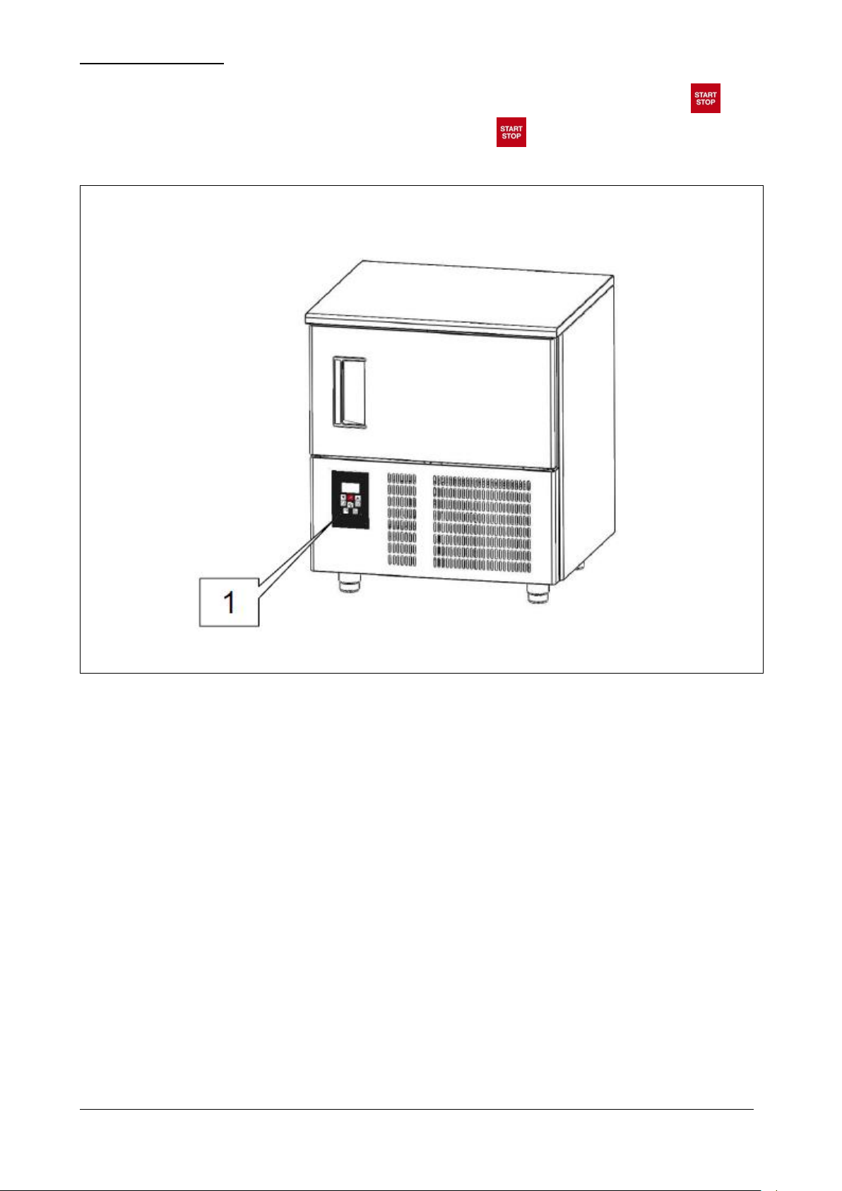
1 – GENERAL INFORMATION
Fig. 1
Thank you for having chosen one of our blast chillers.
Please read this guide very carefully and make sure it is available to those who will install, use and maintain the
equipment.
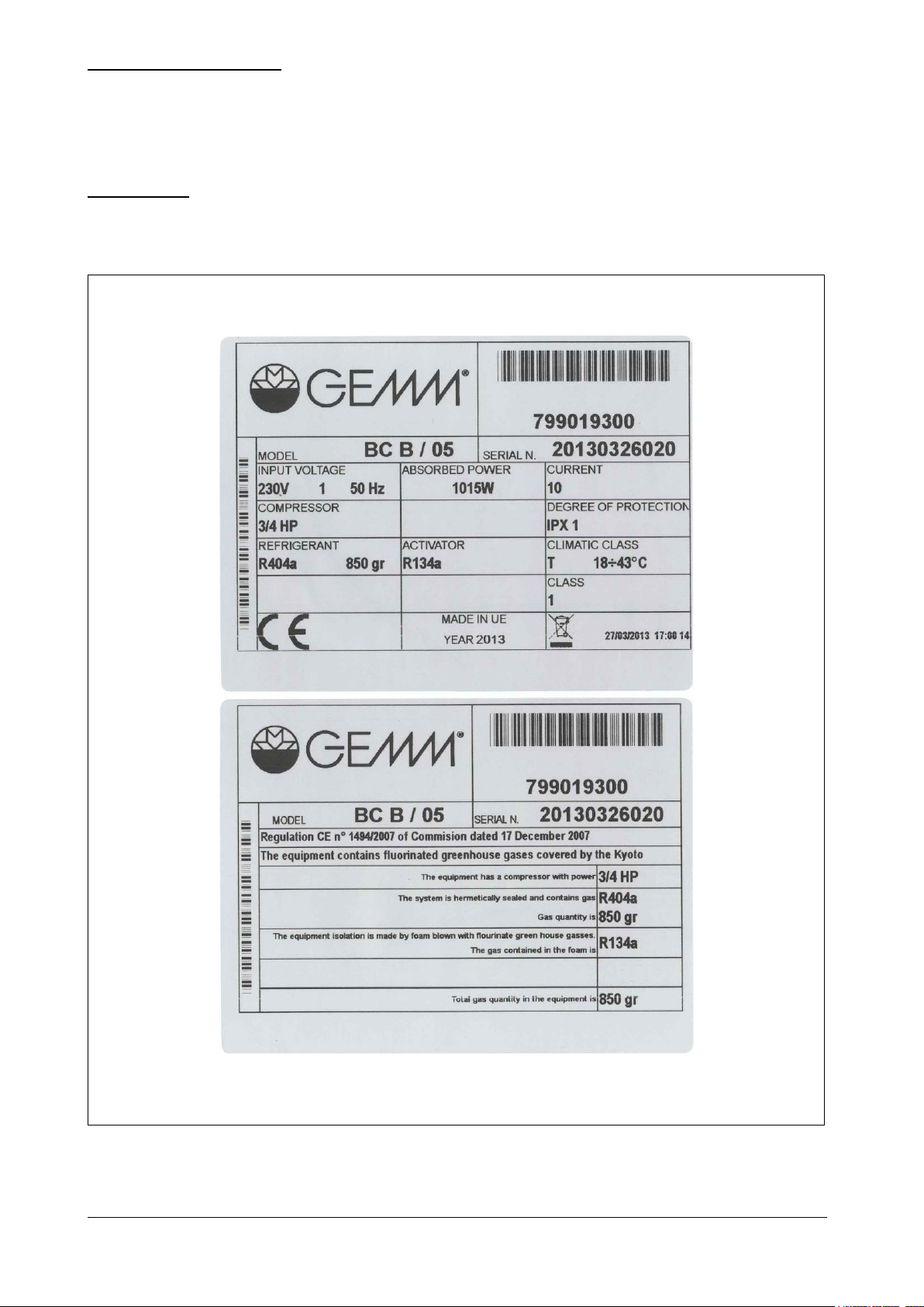
1.1 – MARKING
The ID plates are located on the outside of the appliance, at the bottom of the right side panel towards the front.
Examples are given in Fig. 1 below.
BCB_N Rev.05 05-2015 pag. 6
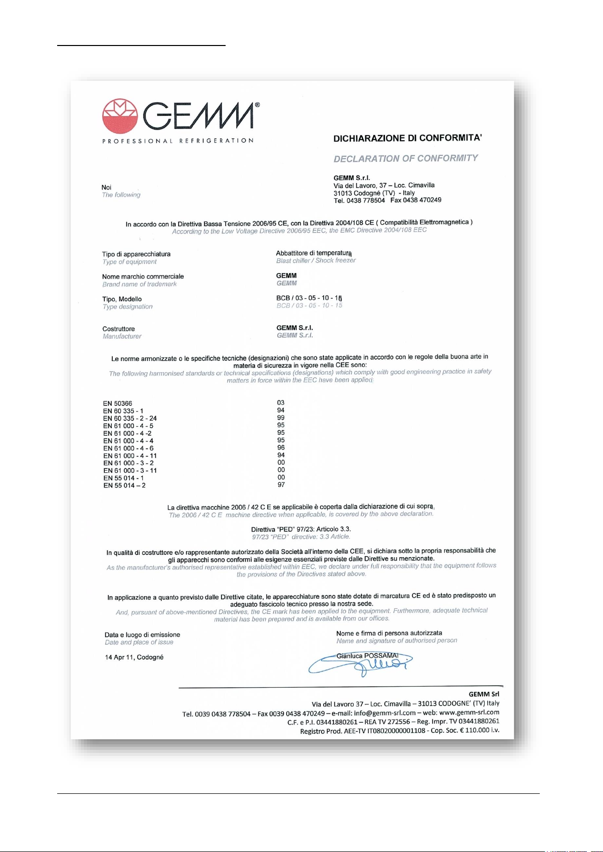
1.2 – DECLARATION OF CONFORMITY
BCB_N Rev.05 05-2015 pag. 7
1.3 – WARRANTY
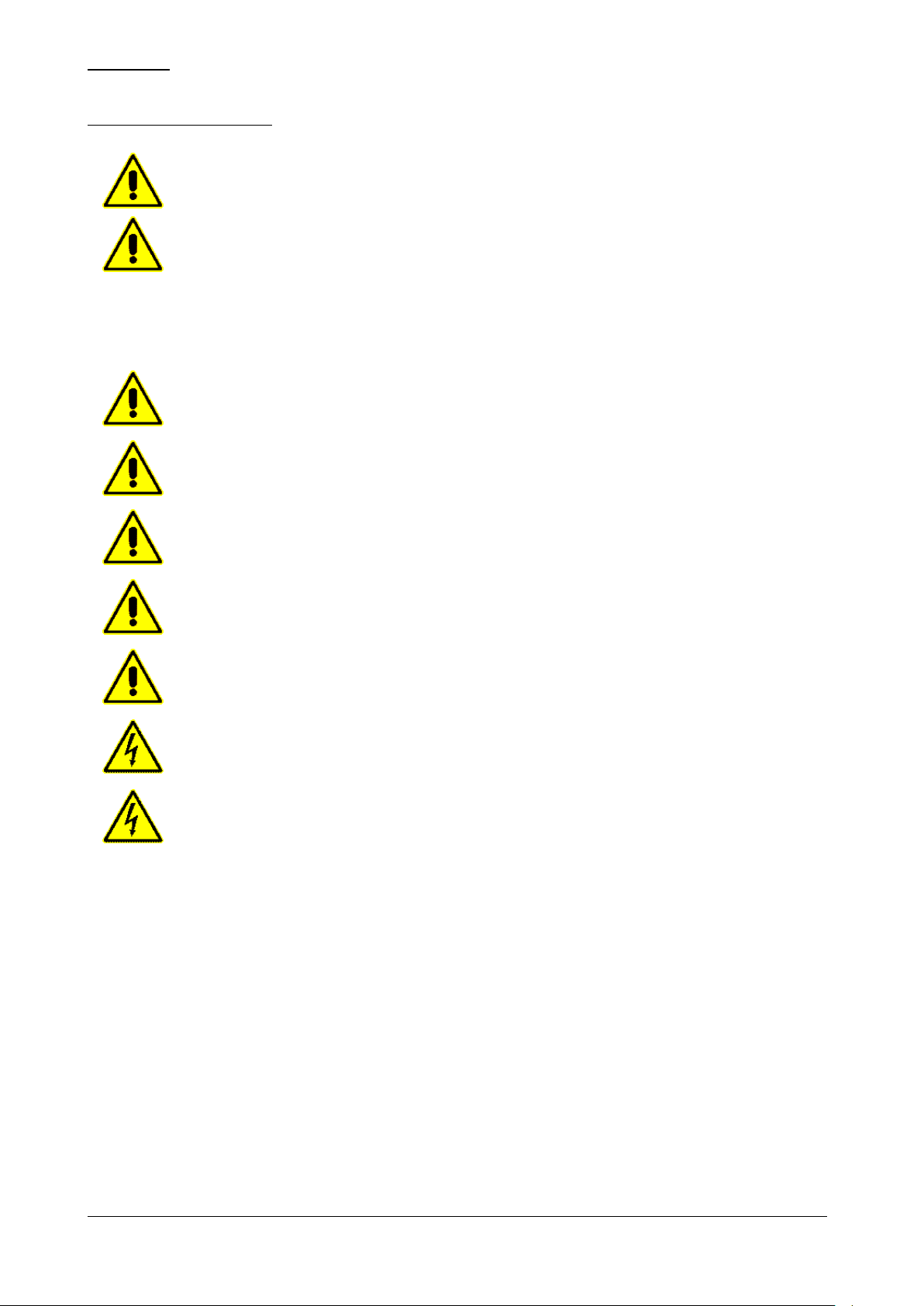
This symbol indicates information and warnings which if not observed could result in damage to the
appliance or jeopardize the safety of personnel.
This symbol indicates information and warnings regarding electrical devices which if not observed could
result in damage to the appliance or jeopardize the safety of personnel.
The warranty covering the various parts of the appliance is valid from the date on the relative delivery note and is as
described in the sales agreement.
The warranty does not cover damage to the appliance caused by:
- transport and/or handling;
- operator errors;
- lack of the maintenance described in this manual;
- faults and/or breakages that cannot be traced to faulty operation of the appliance;
- maintenance operations carried out by unqualified personnel;
- improper use.
1.4 – AFTER-SALES SERVICE
Please contact the manufacturer directly for any needs regarding use, maintenance or ordering of spare parts, and give
the identification details of the appliance to be found on the ID plate.
1.5 – USING AND KEEPING THIS GUIDE
The purpose of this guide is to provide all the necessary information to ensure proper use of the appliance in all safety
and independence.
The guide is divided into sections with paragraphs and sub-paragraphs: the contents page makes it quick and easy to
find any aspect of interest.
The material in this document is provided for information purposes only and may be changed without notice. Although
great care has been taken in preparing the guide, the manufacturer cannot be held liable for damage arising from
errors, omissions or the use made of the information herein.
Keep this guide and all the attached documentation in good condition, legible and complete; keep it near the equipment
in an accessible place known to all operators.
1.5.1 – SYMBOLS USED IN THIS GUIDE
BCB_N Rev.05 05-2015 pag. 8

1.6 – DESCRIPTION OF PERSONNEL
Operators must not carry out work reserved for maintenance engineers or specialised
technicians.
The manufacturer accepts no liability for damage arising from failure to observe this rule.
This guide is for the use of operators, authorized installers and maintenance engineers.
- Appliance operator: specialised person who can operate the appliance in normal working conditions by using
the relevant controls. The operator must also be capable of carrying out simple routine maintenance (cleaning,
loading) and starting or resetting the appliance after a power failure.
- Specialised electrician: specialised electrician who has been trained by the manufacturer to work on the
appliance. The specialised electrician must be capable of installing the appliance and operating it in normal
conditions; he/she is qualified to carry out all electrical and mechanical adjustments, maintenance and repairs.
He/she is able to operate with live switchgear and connector blocks.
- Qualified forklift operator: person qualified in handling materials on company premises, holder of a licence for
the use of forklift trucks.
BCB_N Rev.05 05-2015 pag. 9
2 – DESCRIPTION OF THE APPLIANCE
Model
BCB/03
External dimensions
cm
65 x 67 x 67h
Weight
kg
65
Trays
No.
3 GN (cm 53 x 32.5)
Chamber temperature
°C
+ 95 / - 40
Output
kg
10 (+ 65 °C ÷ + 3 °C); 7 (+ 65 °C ÷ - 18 °C)
Gas
R 404 a
Compressor power
Hp
1/2
Max. absorbed power
W
600
Power supply voltage
Volt 1x230 ~ 50 Hz
Table 1/a
R
Alimentazione elettrica: cavo 3x1.5 mm2 completo di spina Schuko; L=4000 mm
Electricity supply: 3x1.5 mm2 wire complete with Schuko plug; L=4000 mm
Elektrischer Stromanschluss: Kabel 3x1,5 mm2 komplett mit Schukostecker; L=4000 mm
Alimentation électrique: câble 3x1.5 mm2 avec fiche Schuko; L=4000 mm
Fig. 2/a
2.1 –TECHNICAL DATA
BCB_N Rev.05 05-2015 pag. 10
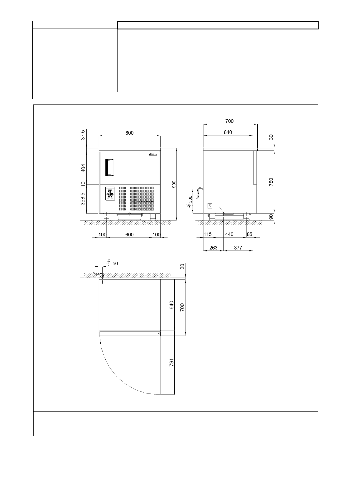
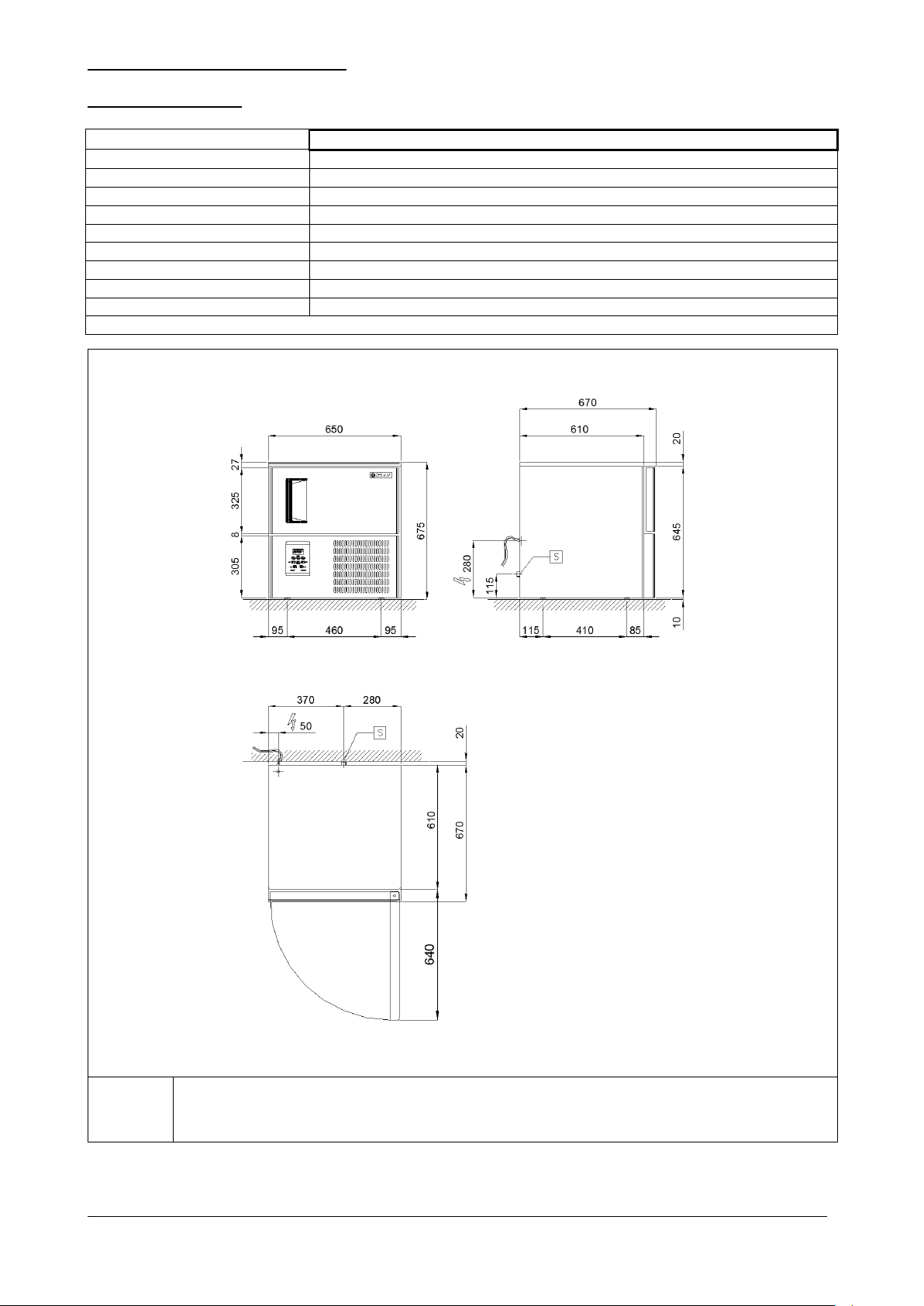
Model
BCB/05
External dimensions
cm
80 x 70 x 90h
Weight
kg
92
Trays
No.
5 EN (cm 60 x 40) or 5 GN (cm 53 x 32.5)
Chamber temperature
°C
+ 95 / - 40
Output
kg
15 (+ 65 °C ÷ + 3 °C); 9 (+ 65 °C ÷ - 18 °C)
Gas
R 404 a
Compressor power
Hp
3/4
Max. absorbed power
W
1100
Power supply voltage
Volt 1x230 ~ 50 Hz
Table 1/b
R
Alimentazione elettrica: cavo 3x1.5 mm2 completo di spina Schuko; L=4000 mm
Electricity supply: 3x1.5 mm2 wire complete with Schuko plug; L=4000 mm
Elektrischer Stromanschluss: Kabel 3x1,5 mm2 komplett mit Schukostecker; L=4000 mm
Alimentation électrique: câble 3x1.5 mm2 avec fiche Schuko; L=4000 mm
Fig. 2/b
BCB_N Rev.05 05-2015 pag. 11
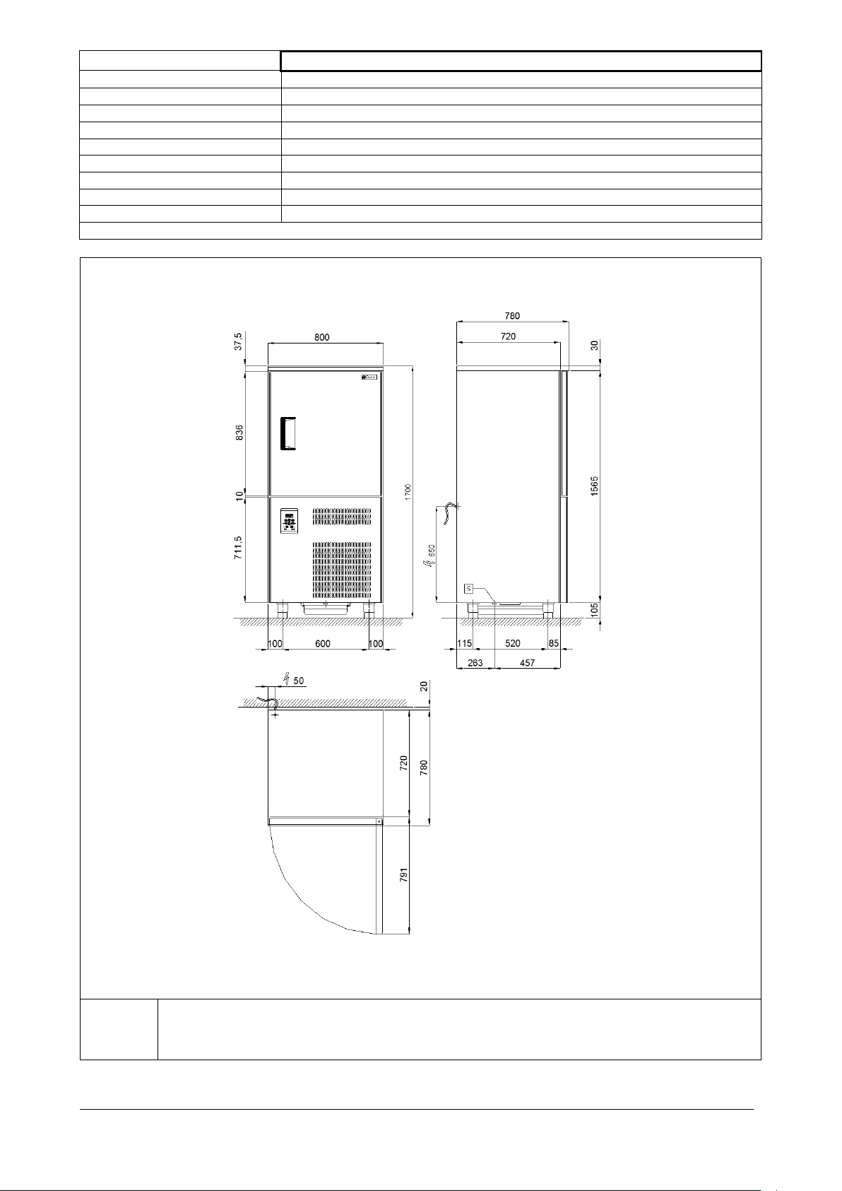
Model
BCB/10
External dimensions
cm
80 x 78 x 170h
Weight
kg
145
Trays
nr
10 EN (cm 60 x 40) or 10 GN (cm 53 x 32,5)
Chamber temperature
°C
+ 95 / - 40
Output
kg
26 (+ 65 °C ÷ + 3 °C); 16 (+ 65 °C ÷ - 18 °C)
Gas
R 404 a
Compressor power
Hp
1,5
Max. absorbed power
W
1628
Power supply voltage
V. 1x230 ~ 50 Hz
Table 1/c
R
Alimentazione elettrica: cavo 3x1.5 mm2 completo di spina Schuko; L=4000 mm
Electricity supply: 3x1.5 mm2 wire complete with Schuko plug; L=4000 mm
Elektrischer Stromanschluss: Kabel 3x1,5 mm2 komplett mit Schukostecker; L=4000 mm
Alimentation électrique: câble 3x1.5 mm
2
avec fiche Schuko; L=4000 mm
Fig. 2/c
BCB_N Rev.05 05-2015 pag. 12
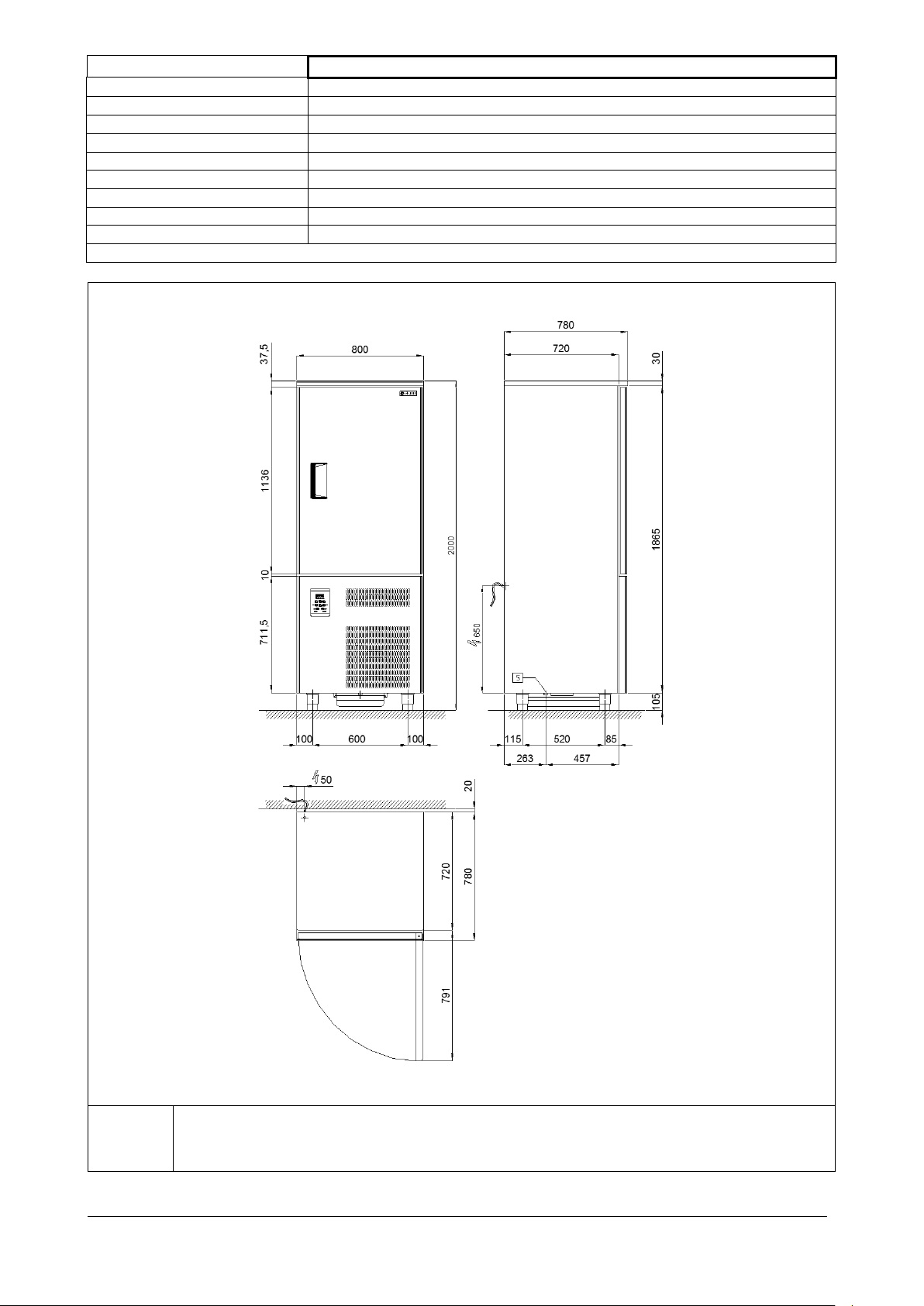
Model
BCB/15
External dimensions
cm
80 x 78 x 200h
Weight
kg
175
Trays
nr
15 EN (cm 60 x 40) or 15 GN (cm 53 x 32,5)
Chamber temperature
°C
+ 95 / - 40
Output
kg
43 (+ 65 °C ÷ + 3 °C); 32 (+ 65 °C ÷ - 18 °C)
Gas
R 404 a
Compressor power
Hp
3
Max. absorbed power
W
2986
Power supply voltage
Volt 3x400 ~ 50 Hz
Table 1/d
R
Alimentazione elettrica: cavo 3x1.5 mm2 completo di spina Schuko; L=4000 mm
Electricity supply: 3x1.5 mm2 wire complete with Schuko plug; L=4000 mm
Elektrischer Stromanschluss: Kabel 3x1,5 mm2 komplett mit Schukostecker; L=4000 mm
Alimentation électrique: câble 3x1.5 mm
2
avec fiche Schuko; L=4000 mm
Fig. 2/d
BCB_N Rev.05 05-2015 pag. 13
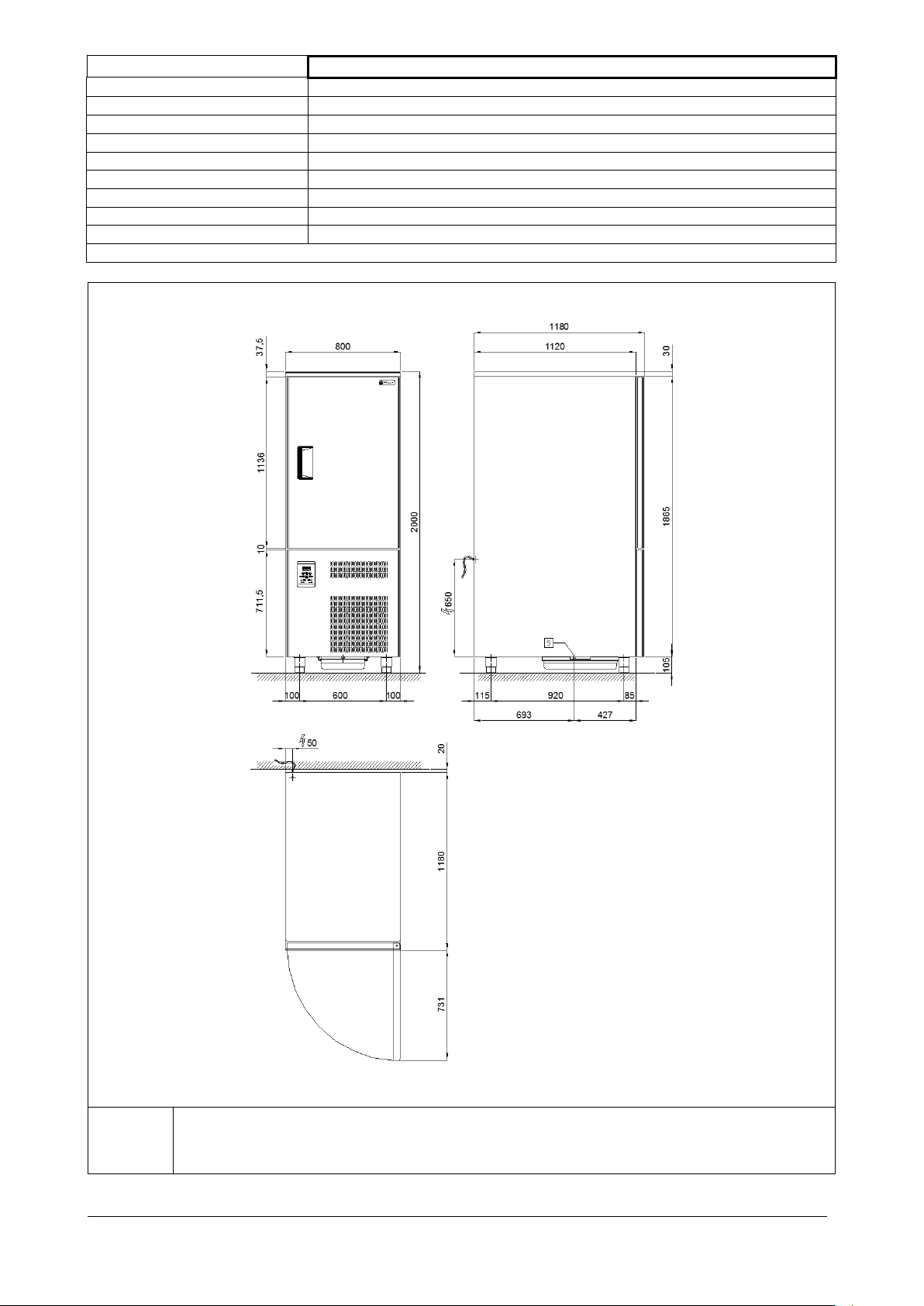
Model
BCB/24
External dimensions
cm
80 x 118 x 200h
Weight
kg
203
Trays
nr
12 EN (cm 60 x 80) or 12 GN 2/1 (cm 53 x 65)
Chamber temperature
°C
+ 95 / - 40
Output
kg
43 (+ 65 °C ÷ + 3 °C); 32 (+ 65 °C ÷ - 18 °C)
Gas
R 404 a
Compressor power
Hp
3.7
Max. absorbed power
W
4312
Power supply voltage
Volt 3x400 ~ 50 Hz
Table 1/e
R
Alimentazione elettrica: cavo 3x1.5 mm2 completo di spina Schuko; L=4000 mm
Electricity supply: 3x1.5 mm2 wire complete with Schuko plug; L=4000 mm
Elektrischer Stromanschluss: Kabel 3x1,5 mm2 komplett mit Schukostecker; L=4000 mm
Alimentation électrique: câble 3x1.5 mm
2
avec fiche Schuko; L=4000 mm
Fig. 2/e
BCB_N Rev.05 05-2015 pag. 14
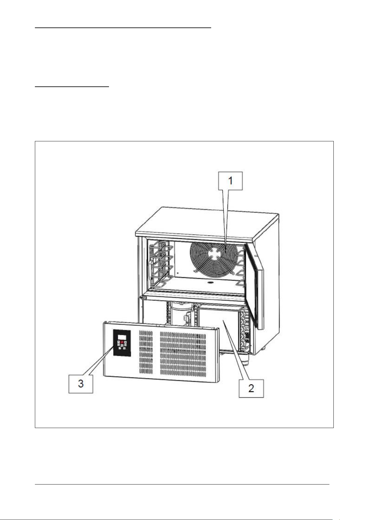
2.2 – DESCRIPTION OF THE BLAST CHILLER AND INTENDED USE
Fig. 3
Blast chillers are appliances with a powerful refrigeration system that can rapidly reduce the core temperature of food.
Ideal for use in kitchens, bakeries and ice cream establishments.
The main work cycles of the appliance are CHILLING and FREEZING. Each cycle has two different end-of-cycle modes
that also correspond to the start of the hold mode: temperature controlled (when the core temperature probe inserted
into the product reaches the set temperature) or time controlled (when the set time expires).
2.2.1 – MAIN COMPONENTS
The appliance comprises the following parts:
body;
condenser unit (ref. 2, fig. 3);
evaporator unit (ref. 1, fig. 3);
control panel (ref. 3, fig. 3)
BCB_N Rev.05 05-2015 pag. 15

2.3 – NOISE
Installation site
Bakeries, confectioneries, ice cream makers, and kitchens in general
Relative humidity
< 80% without condensation
Climatic class
“T” + 18 °C ÷ + 43 °C
Table 2
The appliance is designed and built to keep its noise level as low as possible.
2.4 –AMBIENT CONDITIONS
BCB_N Rev.05 05-2015 pag. 16
3. – SAFETY
IMPORTANT: before using the appliance read this guide carefully and follow the technical operating
instructions and indications to the letter. The operator must know the position and function of all the
control devices as well as the characteristics of the blast chiller.
The blast chiller complies with current safety laws and regulations, but misuse may cause injury to
persons or damage to property.
At the time of installation all operatives must be suitably trained in accident hazards, operator safety
devices, general accident prevention regulations established by international directives and the current
law in the countries where the appliance is used. The appliance must be started up and used exclusively
by trained staff. The behaviour of operators must in any case scrupulously comply with the accident
prevention regulations in the country where the appliance is used.
Do not remove or deface the plates fitted to the appliance by the manufacturer.
The blast chiller must not be used if the control panel or any other part is damaged.
Do not obstruct the front or rear air vents on the appliance; do not place food to be processed against
the ventilation grilles, air ducts or directly on the cabinet floor.
Promptly report any malfunction.
Use only accessories recommended by the manufacturer.
Do not expose the appliance to rain or sprays of water.
Disconnect the appliance from the electricity supply before carrying out any routine or extraordinary
maintenance which involves opening the control panel/switchboard or disassembling any part of the
blast chiller.
3.1 – GENERAL WARNINGS
The manufacturer is relieved from all liability in the following cases:
failure to carry out scheduled maintenance;
unauthorized alterations or work:
use of other than original spare parts;
failure to observe any part of the contents of this guide;
misuse of the appliance.
Any tampering with or unauthorized replacement of one or more appliance parts or components and use of
other than original accessories and consumables can create a hazard and relieve the manufacturer from any
civil or criminal liability.
If in doubt about appliance operation, refrain from using it and contact the manufacturer.
BCB_N Rev.05 05-2015 pag. 17
3.2. – PRECAUTIONS FOR USE
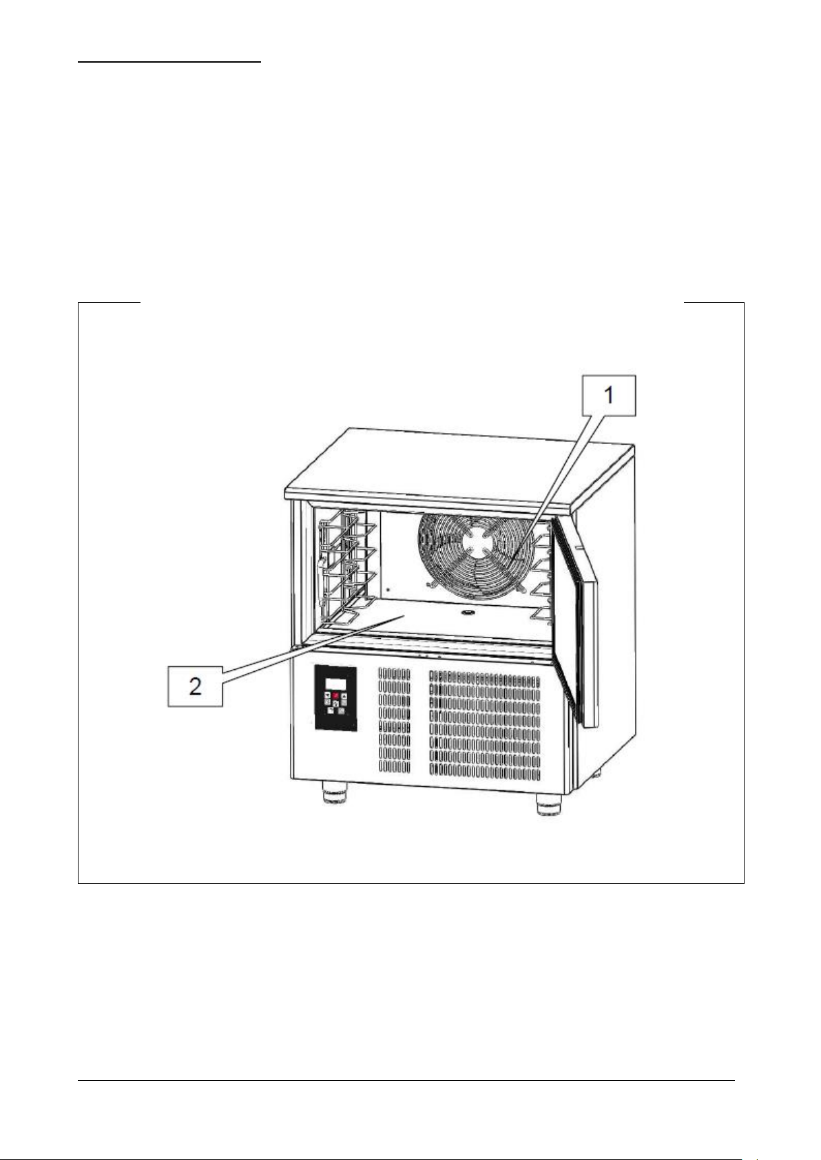
Fig. 4
The blast chiller must not be used:
for purposes other than those given in paragraph 2.2 “Description of the blast chiller and intended use”;
if safety systems are not working;
after incorrect installation;
by untrained personnel;
when maintenance has not been carried out or has been carried out badly;
when other than original spare parts have been used;
with damaged power lead or electrical socket;
with obstructed air ducts (ref. 1 fig. 4);
with the food to be processed placed against the ventilation grilles (ref. 1 fig. 4), air ducts or on the cabinet floor
(ref. 2 fig. 4).
BCB_N Rev.05 05-2015 pag. 18
3.3 – SAFETY DEVICES
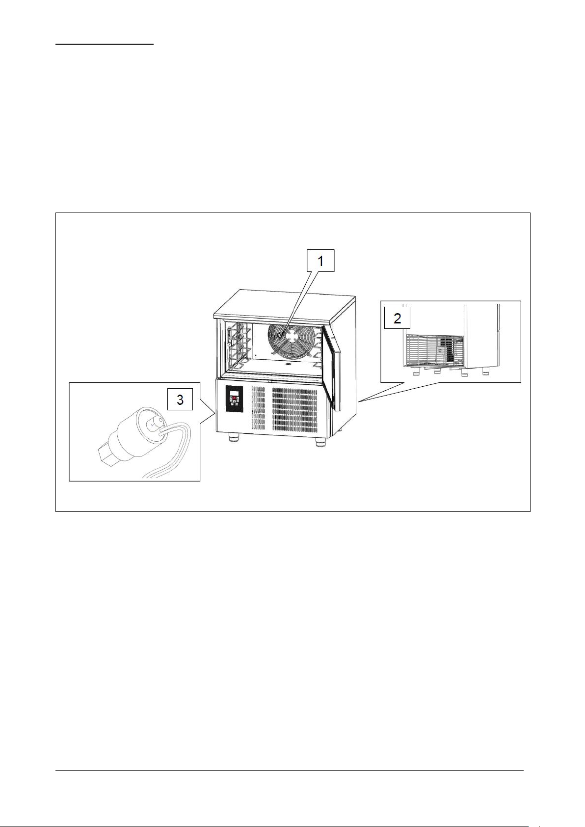
Fig. 5
Special safety devices on the appliance protect personnel exposed to the hazards inherent in moving parts.
grilles covering the cooling fans (ref. 1 fig. 5);
grilles covering the condenser unit (ref. 2 fig. 5).
The appliance is also provided with devices to protect the food during processing. Below is a list of the safety devices
on the appliance.
Sensor, which detects and signals door opening. If the door remains open for a preset time, the message “ id ”
appears on the display, a sound signal is activated and the compressor switches off.
Sensor (ref. 3 fig. 5), located on the cooling circuit, signals any overheating of the equipment and puts the
appliance in standby mode.
BCB_N Rev.05 05-2015 pag. 19
3.4 – STOP FUNCTIONS
Fig. 6
The entire appliance is controlled by an electronic circuit board. The stop function is represented by the button
(ref. 1 fig. 6). Whatever condition the machine is in, holding down the button for 3 seconds cuts out the circuit
board.
BCB_N Rev.05 05-2015 pag. 20
4 – TRANSPORTATION AND HANDLING
The appliance must never be overturned.
The pack must be firmly and stably placed on the floor of the means of transport and secured by
appropriate ropes.
Take the utmost care when lifting and positioning the blast chiller so as to avoid serious injury to
persons or damage to property. The manufacturer cannot be held liable if the indications for
lifting and transporting the blast chiller are not observed.
The ambient temperature must never drop below 4°C during transportation.
Take care when lifting and handling the blast chiller; there is the danger of even fatal injury with
loads being moved.
All handling and lifting must be carried out with extreme care, making sure that all personnel,
without exception, are at a safe distance and that no-one is loitering under suspended loads,
whether stationary or moving.
Before starting any movement, check the whole appliance handling area to identify any
dangerous points.
The ambient temperature must never drop below 4°C during transport.
4.1 – TRANSPORTATION OF THE BLAST CHILLER
Suitable packaging for the type, size and weight of the appliance has been used to ensure it is not damaged during
transit and is delivered intact to the purchaser.
The blast chiller must be placed upright on a pallet wrapped in its own cardboard for the entire time it is being
transported.
The blast chiller is handed over to the carrier ready to be handled.
Once the blast chiller has been unpacked, the packaging material must be disposed of or recycled in accordance with
the laws in force in the country where the appliance is being installed.
4.2. – HANDLING THE PACKAGED BLAST CHILLER
AUTHORIZED PERSONNEL
Specialised forklift truck operator.
Personal protective equipment:
- safety shoes;
- safety gloves.
Personnel carrying out such operations must not wear rings, wrist watches, jewellery, loose or unfastened garments,
such as ties, torn garments, scarves, unbuttoned jackets or tunics with open zips, etc. In general, personnel must wear
safety apparel.
BCB_N Rev.05 05-2015 pag. 21
4.2.1 – WEIGHT AND DIMENSIONS OF THE BLAST CHILLER
Model
BCB/03
BCB/05
BCB/10
BCB/15
BCB/24
Dimensions
cm
65x65x67h
80x70x90h
80x78x170h
80x78x200h
80x118x200h
Weight
kg
76
107
166
202
230
Table 3
The use of unsuitable equipment can cause accidents to those involved in the handling or
damage to the appliance.
The manufacturer cannot be held liable for incorrect and non-compliant use of equipment for
lifting, transport and handling.
4.2.2 – NECESSARY EQUIPMENT
- To lift the appliance, use a forklift truck with suitable minimum lifting power.
BCB_N Rev.05 05-2015 pag. 22
5 – INSTALLATION
Take every precaution when handling the appliance so as to avoid injury to persons or damage to
property.
Do not start the appliance if there are faults on the control panel or damaged parts.
Check that the packing has not been damaged during transport.
The use of unsuitable equipment can cause accidents to those involved in the handling or
damage to the appliance.
The manufacturer cannot be held liable for incorrect and non-compliant use of equipment for
lifting, transport and handling.
AUTHORIZED PERSONNEL
Specialized electrician.
Personal protective equipment:
safety shoes;
safety gloves.
Personnel carrying out such operations must not wear rings, wrist watches, jewellery, loose or unfastened garments,
such as ties, torn garments, scarves, unbuttoned jackets or tunics with open zips, etc. In general, personnel must wear
safety apparel.
5.1 – PREPARATION FOR INSTALLATION
For installation, prepare an area to work in which is suitable for the size of the appliance (see fig. 2) and the chosen lifting
equipment.
The installation site must be set up with all the cabling and connecting systems required for the appliance to work.
The installation site must satisfy the requirements that will allow the appliance to be used in all safety. The area must
have a solid flat floor providing good support, with a finish that ensures a suitable and safe working place for personnel.
The installation site must have natural or artificial lighting suitable for the work to be carried out (in compliance with
specific regulations).
5.2 – UNPACKING
5.2.1 – NECESSARY EQUIPMENT
Use a forklift truck or equivalent equipment to lift the appliance.
BCB_N Rev.05 05-2015 pag. 23
5.2.2 – UNPACKING PROCEDURE
All handling and unpacking must be carried out with extreme care, making sure that all
personnel, without exception, are at a safe distance and that no-one is loitering under
suspended loads, whether stationary or moving.
AFTER INSTALLING THE APPLIANCE, WAIT AT LEAST TWO HOURS BEFORE SWITCHING ON.
The use of unsuitable equipment can cause accidents to those involved in the handling or
damage to the appliance.
The manufacturer cannot be held liable for incorrect and non-compliant use of equipment for
lifting, transport and handling.
All handling and unpacking must be carried out with extreme care, making sure that all
personnel, without exception, are at a safe distance and that no-one is loitering under
suspended loads, whether stationary or moving.
To unpack the appliance, simply remove the cardboard wrapping. Then remove the appliance from the pallet using a
forklift truck, ensuring that the forks are inserted under the appliance and taking care not to damage the two water
tray runners.
5.3 – HANDLING THE BLAST CHILLER
5.3.1 – NECESSARY EQUIPMENT
See paragraph 5.2.1.
5.3.2 – PROCEDURE FOR MOVING THE UNPACKED BLAST CHILLER
To move blast chillers fitted with wheels, release the brakes on the wheels and push, taking care to lock the brakes again
when the appliance is in its final location.
To move blast chillers fitted with feet, lift with a suitable forklift truck; the forks must be inserted under the appliance
taking care not to damage the two water tray runners.
5.4 – ASSEMBLING THE BLAST CHILLER
The blast chiller is delivered to the customer fully assembled.
Remove the water tray from the cabinet and place it under the appliance, sliding it along the runners placed between the
feet.
BCB_N Rev.05 05-2015 pag. 24
6 – SETTING UP
AFTER INSTALLING THE APPLIANCE, WAIT AT LEAST TWO HOURS BEFORE SWITCHING ON.
Electrical connection must be carried out by a specialized electrician.
Check that the power supply voltage given on the ID plate corresponds to the mains voltage
available at the installation site.
The electrical system must conform to current wiring regulations; the mains supply must have
an efficient earthing system compliant with the electrical codes and regulations in the country;
this is the responsibility of the customer.
Avoid sharp bends or kinks in the power cord and do not place any object whatsoever on top of
it.
If it is necessary to unplug from the mains supply, first make sure the circuit board is on OFF
on the display.
The manufacturer cannot be held liable for any damage or accidents caused by failure to comply
with these rules and regulations.
Adjustments carried out by unauthorized personnel may damage the appliance and expose the
operator to serious hazards. Adjustments by unauthorized personnel are considered as
tampering with the appliance and as such invalidate the warranty and relieve the manufacturer
from any liability.
6.1 – CONNECTIONS
6.1.1 – ELECTRICAL CONNECTION
ELECTRICAL CONNECTION PROCEDURE
The appliance is supplied by the manufacturer complete with power plug. Simply connect the power plug to a socket at
the installation site; the system must conform to current regulations.
The electricity supply at the installation site must satisfy the following requirements:
Voltage: 230 Vac
Frequency: 50 Hz
6.2 – PRELIMINARY CHECKS
The electrician-installer must instruct the operator on how to use the blast chiller correctly and explain the basic
maintenance to be carried out.
METHOD
The blast chiller must be prepared for initial start-up by a specialised engineer, in the presence of the operator who will
use the appliance so that the operator can acquire a minimum working knowledge to help him/her carry out allowed
routine maintenance and cleaning.
Before switching on the appliance, a series of checks and inspections must be carried out to prevent errors or accidents
during start up.
Check that the appliance has not been damaged during transport.
Check very carefully for any damage to the control panel/switchboard, pushbutton control, wiring and pipes.
Check that all external power sources have been connected properly.
Check that the machine is perfectly level.
6.2.1 – ADJUSTMENTS
BCB_N Rev.05 05-2015 pag. 25
7 – USE
AFTER INSTALLING THE APPLIANCE, WAIT AT LEAST TWO HOURS BEFORE SWITCHING ON.
COLD BURN HAZARD
During operation the appliance can reach extremely low temperatures: avoid direct contact with
the internal parts immediately after opening the door.
7.1 – INTENDED USE
Blast chillers are appliances with a powerful refrigeration system that can rapidly reduce the core temperature of food.
Ideal for use in kitchens, bakeries and ice cream establishments.
The main work cycles of the appliance are CHILLING and FREEZING. Each cycle has two different end-of-cycle modes
that also correspond to the start of the hold mode: temperature controlled (when the core temperature probe inserted
into the product reaches the set temperature) or time controlled (when the set time expires).
- SOFT CHILLING. “Delicate” positive chilling (+3°C). Food just out of the oven is brought quickly to a
temperature of 3°C in no more than 90’, thus inhibiting bacterial proliferation and avoiding dehydration of the
cooked food due to evaporation. Food treated in this way can be stored perfectly for 5-7 days without any
alteration to its original qualities.
- HARD CHILLING. “Intense” positive chilling (+3°C). This mode also lasts for a maximum of 90’ and is used
when the food to be chilled is thicker than 2-3 centimetres (i.e. large joints), dense or fatty. The appliance air
temperature varies to accelerate penetration of the cold into the food.
- FREEZING. Shock freezing or freezing (-18°C). This work cycle brings the core temperature of the food to 18°C in less than four hours (240’). The speed of the process prevents large ice crystals from forming, ensuring
that when it is used the thawed food has its original texture, colour and quality.
- HOLDING. At the end of both the chilling and freezing cycles the machine automatically goes to the set holding
temperature.
7.2 – INAPPROPRIATE USE
Blast chillers cannot be used for purposes other than those described in point 7.1. In particular the appliance is not
suitable for storing food for an indefinite period.
7.3 – RESIDUAL RISKS
BCB_N Rev.05 05-2015 pag. 26
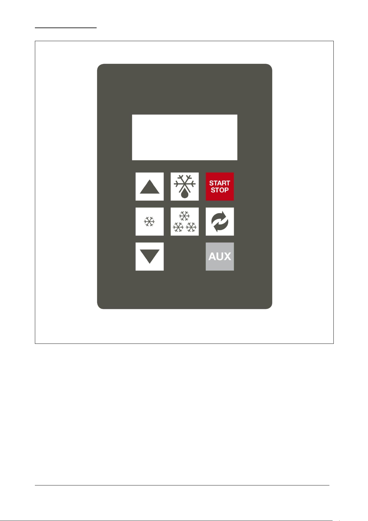
7.4 – CONTROL PANEL
Fig. 7
BCB_N Rev.05 05-2015 pag. 27
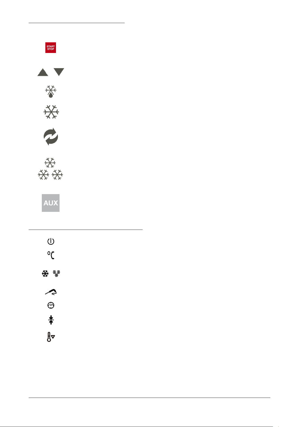
The buttons on the control panel are as follows:
BUTTON 0/1, START/STOP
When the appliance is OFF (0), press just once to pass to
STANDBY (1). When the appliance is in STANDBY press just
once to START a cycle. When a cycle is in progress, press just
once to STOP. Whatever the appliance status, if the button is
held down for 3 seconds the circuit board is put to OFF.
+ AND - BUTTONS
Used to increase or decrease the value shown on the display.
DEFROST BUTTON
With the appliance in STANDBY or during the storage, press just
once to start a defrost cycle.
CHILLLING BUTTON
With the appliance in STANDBY, press just once to select a
chilling cycle.
Hold the button down for 3 seconds to start the continuous cycle.
HARD/SOFT BUTTON
With the cycle selected, press just once to select the HARD or
SOFT mode.
FREEZING BUTTON
With the appliance in STANDBY, press just once to select a
freezing cycle.
AUXILIARY BUTTON
Press this button to use the accessory, such as UV lamp, warmed
core probe, when installed.
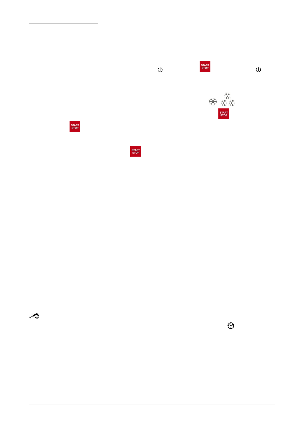
OFF
Only lit when the appliance is OFF, otherwise always off.
CELSIUS
May be lit red or green to show the temperature unit of
measurement.
CHILLING AND FREEZING
Blinking when the relative cycles are in progress; lit during the
subsequent hold cycle.
TEMPERATURE
Lit during a temperature-controlled cycle
TIME
Lit during a time-controlled cycle.
HOLDING
Lit or blinking when in the hold mode.
CONTINUOUS CYCLE
Lit or blinking during the pre-cooling phase, also CONTINUOUS
CYCLE.
The following icons are present on the controller display:
BCB_N Rev.05 05-2015 pag. 28
7.5 – CONTROL PROCEDURES
The entire appliance is controlled by an electronic circuit board.
As soon as the appliance is connected to the electricity supply, the whole display lights up for a “lamp-test” lasting a few
seconds, At the end of the lamp test, the display returns to the condition it was in before being switched off. In
particular, if a cycle was in progress at the time, it will re-start from the point at which it was interrupted.
With the circuit board OFF the display is not lit except for the icon. Press the button to turn off the icon on
the display and go into STANDBY mode; the cabinet temperature appears in blue on the display.
Use the controls on the panel, helped by the indications on the display, to activate the various appliance functions.
With the circuit board in STANDBY, pass from one cycle to another by simply pressing , .
With the circuit board in STANDBY and a cycle selected, start the cycle by pressing the (START) button once.
Similarly, press the (STOP) button just once to stop the cycle in progress.
If the buzzer sounds for any reason whatsoever, it may be muted by simply pressing any button.
Whatever the appliance status, holding down the button for 3 seconds puts the circuit board to OFF.
7.6 – USE PROCEDURES
Before using the appliance, the inside of the cabinet should be thoroughly cleaned.
When switching on after installation or if the appliance has not been used for a long time, it is a good rule to let it operate
empty until the set temperature has been reached.
To get the best performance from the blast chiller, arrange the products so that air can circulate properly: do not obstruct
the fan, do not stack trays on top of each other, distribute the load neatly and do not cover the containers with lids or
cling film.
To avoid unwanted changes in the food, do not load the appliance with more than the allowed quantities, do not use
pieces thicker than 50-70 mm and avoid pointlessly opening the door.
Clean and sterilise the core probe before use. The probe must be inserted into the centre of the largest joint or piece,
taking care that the point does not go right through and come into contact with the tray.
To improve the efficiency of either the chill or freeze working cycle, we recommend pre-cooling the cabinet by
switching the appliance on at least 15 min before inserting the product.
When any cycle is selected the electronic circuit board checks the temperatures read by the cabinet sensor and
the core probe to assess correct insertion of the probe (AUTOMATIC probe acknowledgement). This check lasts
just over 2 minutes and then, in accordance with set parameters and provided the probe is properly inserted, a
temperature-controlled cycle starts. In this case the temperature of the core probe will be displayed and the icon
lights up.
A failed test is indicated by activation of the buzzer for one minute, after which the icon will light up on the
display and a time-controlled cycle starts.
BCB_N Rev.05 05-2015 pag. 29
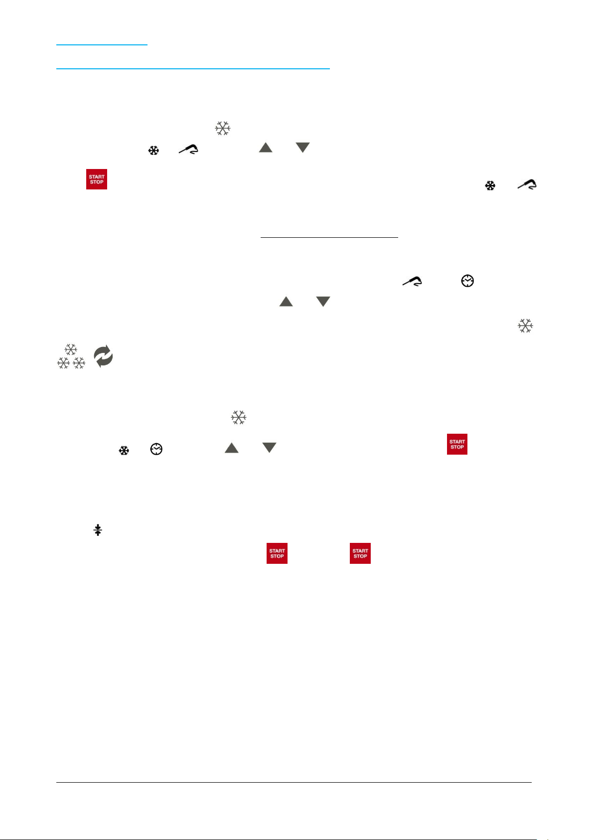
7.7 – SOFT CHILLING
7.7.1 – SELECTING AND SETTING OF SOFT CHILLING CYCLE
Load the appliance suitably with the food to be chilled, insert the core probe correctly into the product for a temperaturecontrolled cycle, and close the door.
With the appliance on STANDBY press : the cabinet set point temperature related to the - 5°C cycle appears on the
display while the icons and blink. Use the and buttons to change this value.
Press (START) to start the cycle: the cabinet temperature appears on the display while the icons and
remain lit. As already explained, once the cycle is confirmed, the device carries out an automatic acknowledgement of
probe insertion (approx. 2 minutes), at the end of which the temperature-controlled cycle (with probe) will be confirmed or
the appliance will pass to the time-controlled cycle. All this is done AUTOMATICALLY.
If the test is passed, the device confirms the temperature-controlled cycle (with probe) and the probe temperature
appears on the display.
If the test is failed, after the buzzer alarm and visual warning given by the blinking icon , the icon appears on the
display and the cycle becomes time controlled. Use the and buttons to change this value.
While the residual time is being displayed, the cabinet temperature may also be displayed by simply pressing the ,
, buttons.
The time-controlled cycle may be selected DIRECTLY, bypassing the automatic probe acknowledgement stage.
With the appliance in STANDBY press the button TWICE: the duration of the cycle, 90 min, appears on the display
while the icons and blink. Use the and buttons to change this value. Then press (START) to start
the cycle.
When the 90’ cycle has elapsed or when the core temperature of +3°C has been reached, the buzzer sounds and the
device automatically starts the hold cycle with +2°C cabinet temperature.
The icon lights up on the display.
The cycle can be interrupted at any time by pressing (STOP): press (START) again to restart the cycle.
BCB_N Rev.05 05-2015 pag. 30

7.8 – HARD CHILLING
7.8.1 – SELECTING AND SETTING A HARD CHILLING CYCLE
Load the appliance suitably with the food to be chilled, insert the core probe correctly into the product for a temperaturecontrolled cycle, and close the door.
With the appliance on STANDBY, press : the cabinet set point temperature related to the - 5°C cycle appears on the
display while the icons and blink. Use the and buttons to change this value.
Press the button just once to start the hard cycle. The symbol HARD also starts blinking on the display.
Press (START) to start the cycle: the cabinet temperature appears on the display while the icons and
remain lit. As already explained, once the cycle is confirmed, the device carries out an automatic acknowledgement of
probe insertion (approx. 2 minutes), at the end of which the temperature-controlled cycle (with probe) will be confirmed or
the appliance will pass to the time-controlled cycle. All this is done AUTOMATICALLY.
If the test is passed, the device confirms the temperature-controlled cycle (with probe) and the probe temperature
appears on the display.
If the test is failed, after the buzzer alarm and visual warning given by the blinking icon , the icon appears on the
display and the cycle becomes time controlled. Use the and buttons to change this value.
While the residual time is being displayed, the cabinet temperature may also be displayed by simply pressing the ,
, buttons.
The time-controlled cycle may be selected DIRECTLY, bypassing the automatic probe acknowledgement stage.
With the appliance in STANDBY press the button TWICE: the duration of the cycle, 90 min, appears on the display
while the icons and blink. Use the and buttons to change this value. Then press (START) to start
the cycle.
When the 90’ cycle has elapsed or when the core temperature of +3°C has been reached, the buzzer sounds and the
device automatically starts the hold cycle with +2°C cabinet temperature.
The icon lights up on the display.
The cycle can be interrupted at any time by pressing (STOP): press (START) again to restart the cycle.
BCB_N Rev.05 05-2015 pag. 31

7.9 – FREEZING
7.9.1 – SELECTING AND SETTING A FREEZING CYCLE
Load the machine suitably with the food to be frozen, place the core probe into the food and close the door.
With the appliance on STANDBY press : the display will show the set point temperature of the room referred to
- 40°C cycle, in the meantime the icons and flash. Use the and buttons to edit this value.
Press (START) to start the cycle: the display will show the temperature of the room and the icons and
will remain on. As already explained, once confirmed the cycle, the device does an automatic identification of probe’s
insertion (around 2 minutes), at the end of which the cycle will be confirmed or by probe or by time. All this process will
be made AUTOMATICALLY.
If the test has a positive result, the device will confirm the temperature controller cycle (probe) and the display will show
the temperature of the probe.
Otherwise, if the result is negative, after buzzer’s alarm and visual signalling of the flashing icon , the display will
show the icon and the cycle will change in time controlled cycle. Use the and buttons to edit this value.
During the visualization of the residual time, it is possible to change the temperature of the room by pressing the buttons
, , .
You can DIRECTLY select the cycle time, bypassing the automatic stage of probe recognition.
With the appliance on STANDBY press TWICE : the display will show the duration of the cycle 240 min, in the
meantime the icons and flash. Use the and buttons to edit this value. Than press (START) in
order to start the cycle.
Once finish the time relative to 240’ cycle or once reaches the core temperature of -18°C, the device automatically starts
the conservation cycle, -25°C rooms, previously reported by the buzzer’s alarm.
On the display will appear the icon
The cycle can be interrupted at any time by pressing (STOP): press (START) again in order to restart again
the cycle.
BCB_N Rev.05 05-2015 pag. 32

7.10 – SPECIAL FUNCTIONS AND USES
7.10.1 – PRE-CHILLING FUNCTION or CONTINUOUS CYCLE
If the temperature of the food to be chilled is very high (above 65°C) it is advisable to pre-chill as follows: press the
button for a few seconds, the appliance starts and the LED starts blinking. Once the set point (-30°C) has been
reached, the LED remains on with fixed light and any cycle may be set and the appliance suitably loaded with the food to
be chilled or frozen. The new set cycle will “overwrite” the continuous cycle, without having to switch off the appliance
first.
The continuous cycle is ideal for ice-cream establishments where working cycles are very frequent
(HARDENING). Only the cabinet temperature and not the time parameter is necessary.
7.10.2 – DEFROST
The appliance evaporator is defrosted by stopping the compressor. Defrost can be carried out in the Automatic or
Manual mode and is shown by the readout “ dEF ” appearing on the display first with fixed light then during dripping with
blinking light.
Automatic defrost can only take place during the hold cycle, at intervals of 6 hours with a maximum duration of 15’ and
an evaporator temperature of +8°C.
Manual defrost can be activated when the machine is in STANDBY and the evaporator temperature does not exceed
+8°C, by pressing . Since the compressor is already off in the STANDBY mode, forced ventilation takes place during
Manual defrost and it is therefore advisable to keep the door open throughout the cycle.
7.10.3 – LONG IDLE PERIODS
Switch the appliance OFF by pressing for three seconds, then unplug.
Clean the appliance thoroughly (see paragraph 8.2) and make sure the door is left open at the end of cleaning and
throughout the period that the appliance is not used.
BCB_N Rev.05 05-2015 pag. 33

8 – MAINTENANCE
Contact the manufacturer for any anomaly not described in this guide; also contact the manufacturer
if any doubts arise concerning the maintenance described herein. Maintenance carried out by
unauthorized personnel may damage the appliance and expose the operator to serious hazards.
Maintenance carried out by unauthorized personnel is considered as tampering with the appliance
and as such invalidates the warranty and relieves the manufacturer from any liability.
Switch off the appliance, on the display, and disconnect from the power supply before
carrying out any routine or extraordinary maintenance which involves opening the control
panel/switchboard or disassembling any part of the appliance.
Maintenance carried out on an appliance in which the electrical system is live, may cause
even fatal injury.
Only authorized personnel may deactivate the safety devices so as to guarantee the safety of
persons and prevent damage to the appliance. The safety devices must be correctly activated again
when maintenance is completed.
Unauthorized persons must keep a safe distance from the appliance during maintenance or repairs.
Observe the intervals for making inspections as directed or indicated in this guide.
At the end of maintenance or repairs the appliance may only be started after the specialist engineer
has made sure that:
- all the work has been fully carried out;
- the safety systems are active;
- the appliance is working perfectly;
- no-one is working on the appliance.
Component
Type of work
Timing
Responsibility
Method
Chamber
Cleaning
When needed
Appliance operator
See para. 8.2.2
External part
Cleaning
When needed
Appliance operator
See para. 8.2.3
Condenser
Cleaning
Every 30 days
Appliance operator
See para. 8.2.4
Core probe
Cleaning
Every cycle
Appliance operator
See para. 8.2.5
Table 5
8.1 – SPECIAL PRECAUTIONS
8.2 – ROUTINE MAINTENANCE
8.2.1 – ROUTINE MAINTENANCE TABLE (TABLE 5)
8.2.2 – CLEANING THE CHAMBER INTERIOR
Carry out this operation whenever necessary.
APPLIANCE STATUS:
- ON/OFF button on OFF ( on the display);
- power supply plug disconnected from the mains.
AUTHORIZED PERSONNEL
Appliance operator.
BCB_N Rev.05 05-2015 pag. 34

METHOD
Use exclusively water and non-abrasive neutral detergent for cleaning. The use of different
products could damage the surface of the appliance and compromise the quality and healthiness of
the product being processed.
Do not use abrasive sponges.
When cleaning do not use cloths that leave lint.
Do not use water jets to clean the appliance.
Fig. 8
Clean very carefully the internal part of the chamber, the door closure surface (ref. 1 fig. 8) and gasket (ref. 2 fig. 8),
using a non-abrasive sponge soaked in neutral detergent. Rinse with a sponge soaked in water and dry with a clean
cloth.
Proper cleaning of the inside of the appliance prevents the formation of bad odour which could affect the end product
negatively.
BCB_N Rev.05 05-2015 pag. 35

8.2.3 – CLEANING THE EXTERIOR OF THE APPLIANCE
Only use water and non-abrasive neutral detergent for cleaning. The use of other products could
damage the surface of the appliance and jeopardise the quality and healthiness of the product being
processed.
Do not use abrasive sponges.
When cleaning do not use cloths that could leave lint.
Clean whenever necessary.
APPLIANCE STATUS:
- ON/OFF button on OFF ( on the display);
- power plug disconnected from the mains supply.
AUTHORIZED PERSONNEL
Appliance operator.
METHOD
Clean the external surfaces of the appliance (steel base and panelling) using a sponge soaked with neutral detergent.
neither of which must be abrasive. Rinse thoroughly using a clean sponge soaked with water and then wipe dry using a
clean cloth.
BCB_N Rev.05 05-2015 pag. 36

Fig. 9
The condenser has sharp edges. When carrying out the above work, wear safety gloves, goggles
and face masks.
Do not use direct water jets to clean the appliance.
8.2.4 – CLEANING THE APPLIANCE CONDENSER
Clean once every 30 days.
APPLIANCE STATUS:
- ON/OFF button on OFF ( on the display);
- power plug disconnected from the mains supply.
AUTHORIZED PERSONNEL
Appliance operator.
METHOD
For trouble-free efficient appliance operation, the air-cooled condenser (ref. 1 fig. 9) must be kept clean so that the air
can circulate freely. Cleaning must be carried out once every 30 days. Remove the control panel by loosening the
screws (ref. 2 and 3 fig. 9). Clean with a non-metallic brush to remove all the dust and fluff from the fins. It is advisable
to use a vacuum cleaner so that dust does not float in the air. If there are greasy deposits, remove with a brush soaked
in alcohol. DO NOT SCRAPE THE SURFACES WITH POINTED OR ABRASIVE OBJECTS.
BCB_N Rev.05 05-2015 pag. 37

8.2.5 – CLEANING THE CORE PROBE
Fig. 10
Do not tug the probe cable; you may damage it.
The probe has a very sharp pointed tip. Always wear safety gloves and take great care during
cleaning.
Clean at every cycle.
APPLIANCE STATUS:
- ON/OFF button in position “O” (OFF);
AUTHORIZED PERSONNEL
Appliance operator.
METHOD
The core probe (ref. 1 fig. 10) must always be cleaned before a new cycle so as to avoid “contaminating” the product in
any way. Remove any residue using a sponge soaked in neutral detergent. Rinse with plenty of water and apply a
sterilising product.
BCB_N Rev.05 05-2015 pag. 38

8.3 – EXTRAORDINARY MAINTENANCE
Contact the manufacturer to disassemble the appliance in any way.
If the appliance needs extraordinary maintenance or if malfunctioning occurs that is not described in this guide, contact
the manufacturer.
8.4 – TROUBLESHOOTING
It is important to remember that whatever the appliance status, pressing the button for 3 seconds switches it OFF.
When any malfunction occurs, the buzzer sounds intermittently and a readout appears in red on the display. Whatever
the reason for the buzzer, it can be muted by pressing any button.
8.4.1– ALARMS
The following alarms could appear on the display:
- “ tiME ” temperature-controlled chilling or freezing not finished within the maximum time limit (HACCP alarm).
This alarm has no direct effect, it will simply be stored.
- “ AL ” low temperature alarm. Whatever the cycle in progress, this alarm has no direct effect.
- “ AH ” high temperature alarm. Whatever the cycle in progress, this alarm has no direct effect.
- “ HP ” high pressure switch alarm. In the STANDBY mode it has no direct effect. If triggered during any work
cycle, it causes the cycle to stop and the appliance goes into STANDBY. The cause of the alarm must be
eliminated, then the appliance switched off by pressing for 3 seconds, after which (START) is
pressed again to restart. This alarm could be caused by a high room temperature (higher than allowed; see
par. 2.4) or a dirty condenser (which must be cleaned as described in par. 8.2.4).
- “ id ” door open alarm. This alarm has no direct effect and will stop as soon as the door is closed properly.
8.4.2– ERRORS
Errors acknowledged by the electronic controller are:
- “ Pr 1 ” cabinet sensor error. In STANDBY it prevents cycle start. In the Chilling or Freezing mode it causes
the cycle to stop and the appliance to go onto STANDBY. If in the Hold mode, the cycle is not stopped but the
compressor operates on a cyclic basis to ensure that cabinet temperature is maintained. Check the sensor
connection and replace the sensor if necessary.
- “ Pr 2 ” core probe error. In STANDBY it prevents the start of a temperature-controlled cycle. In the
temperature-controlled Chilling or Freezing mode, it causes the machine to go into a time-controlled cycle.
During the Hold mode it has no direct effect. Check the probe connection and replace the probe if necessary.
- “ Pr 3 ” evaporator sensor error. In the STANDBY, Chilling or Freezing and Hold mode it has no direct effect.
If defrost is taking place, it will end by time-out.
9 – DISASSEMBLY
BCB_N Rev.05 05-2015 pag. 39

10 – DISPOSAL
TAKE CARE: THE APPLIANCE CONTAINS REFRIGERANT GAS THAT MUST BE
CONTROLLED AND RECOVERED ACCORDING TO THE REGULATIONS OF THE COUNTRY IN
WHICH DISPOSAL WILL TAKE PLACE.
Consult the fitter for any disassembly requirements.
10.1 – DISPOSAL METHOD
APPLIANCE STATUS
- electronic circuit board in position “O” (OFF);
- power plug disconnected from the mains supply.
METHOD
The appliance is made of ferrous materials, electronic components and plastics. If it needs to be scrapped, separate the
various components according to the material of which they are made in order to simplify separate waste collection or
possible recycling of parts. The appliance must be disposed of separately from municipal waste.
No special instructions apply to the disassembled appliance. Consign to specialised waste disposal firms or return to the
dealer, if allowed by law (also see “Information to users regarding waste disposal in the European Union” below).
With regard to disposal and scrapping, always consult the laws applicable in the country where the appliance is used
(also see “Information to users regarding waste disposal in the European Union” below).
INFORMATION TO USERS REGARDING WASTE DISPOSAL IN THE EUROPEAN UNION
The symbol of a crossed waste bin on the appliance indicates that at the end of its working life the product must be
collected separately from other waste.
At the end of its working life the user must therefore take the product to a suitable centre for the separate collection of
electronic and electrical waste, or return it to a dealer when purchasing a new appliance of the same type.
Suitable separate waste collection of unwanted appliances and their forwarding to recycling, treatment, recovery and
environmentally friendly disposal makes it possible to avoid potential negative effects on the environment and human
health, and assists recycling and recovery of materials.
Unauthorized disposal of the product by the user is punished by the application of fines established by the countries in
which the appliance is disposed of.
11 – SPARE PARTS
11.1 – ORDERING SPARE PARTS
Contact the manufacturer or authorized dealer to order spare parts.
12 – ENCLOSURES
The appliance comes with the following enclosures:
- Declaration of conformity
- Wiring diagram
- Electrical approval report
- Assessment of vacuum, leakage and gas load for the refrigeration system.
BCB_N Rev.05 05-2015 pag. 40

Abb. 1
1 – ALLGEMEINE INFORMATIONEN
Wir danken Ihnen, dass Sie einen unserer Schockkühler/Froster gewählt haben.
Lesen Sie diese Bedienungsanleitungen sorgfältig durch und stellen Sie diese dem Personal zur Verfügung, das für die
Installation, die Bedienung und die Instandhaltung des Geräts zuständig ist.
1.1 – GERÄTEKENNZEICHNUNG
An der Außenseite des Geräts, rechts unten zur Vorderseite hin, befinden sich die Kennschilder des Geräts: in Abb. 1
bringen wir eine Kopie davon.
BCB_N Rev.05 05-2015 pag. 41

1.2 – KONFORMITÄTSERKLÄRUNG
BCB_N Rev.05 05-2015 pag. 42

1.3 – GARANTIE
Dieses Symbol kennzeichnet Informationen und Hinweise, deren Nichtbeachtung zu Schäden am Gerät
oder Personen führen kann.
Dieses Symbol kennzeichnet elektrische Informationen oder Hinweise, deren Nichtbeachtung zu
Schäden am Gerät oder an Personen führen kann.
Die Garantie auf die Gerätekomponenten gilt ab dem auf dem Lieferschein angegebenen Datum, gemäß den im
Verkaufsvertrag angegebenen Bestimmungen.
Ausgenommen von der Garantie sind Schäden am Gerät, die verursacht werden durch:
- Transport und/oder Handling;
- Fehler des Bedieners;
- nicht laut den Angaben in diesem Handbuch durchgeführte Instandhaltung;
- Defekte und/oder Schäden, die nicht auf Betriebsstörungen des Gerätes beruhen;
- Instandhaltungsarbeiten durch nicht qualifiziertes Personal;
- unsachgemäßen Gebrauch.
1.4 – KUNDENDIENST
Für jede Art von Reparatur, Wartung oder Anforderung von Ersatzteilen wenden Sie sich bitte direkt an den Hersteller,
unter Angabe der auf dem Geräteschild angegebenen Maschinendaten.
1.5 – GEBRAUCH UND AUFBEWAHRUNG DES HANDBUCHS
Dieses Handbuch liefert alle erforderlichen Informationen für die sachgemäße, möglichst autonome und sichere
Bedienung des Gerätes.
Das Handbuch unterteilt sich in Kapitel, Paragraphen und Unterparagraphen: das Inhaltsverzeichnis liefert eine
Übersicht über die einzelnen Kapitel.
Der Inhalt dieser Bedienungsanleitungen dient ausschließlich zur Information und kann ohne Vorankündigung geändert
werden. Obwohl das Handbuch mit äußerster Sorgfalt erstellt wurde, haftet der Hersteller nicht für Schäden auf
Grund von Fehlern oder Unterlassungen und dem Gebrauch der enthaltenen Informationen.
Bewahren Sie das Handbuch samt den Anlagen in gutem und leserlichem Zustand in der Nähe des Gerätes an einem
leicht zugänglichen und allen Bedienern bekannten Ort auf.
1.5.1 – IN DIESEM HANDBUCH ENTHALTENE SYMBOLE
BCB_N Rev.05 05-2015 pag. 43

1.6 – BESCHREIBUNG DES PERSONALS
Die Bediener dürfen keine Operationen durchführen, die dem Instandhaltungsdienst oder den
spezialisierten Technikern zustehen.
Der Hersteller haftet nicht für Schäden, die auf Grund der Nichtbeachtung dieses Verbots
entstehen.
Dieses Handbuch wendet sich an die für die Installation und Instandhaltung des Geräts zuständigen Techniker.
- Für die Bedienung des Geräts zuständiges Personal: Spezialisiertes Personal, das in der Lage ist, das
Gerät unter normalen Bedingungen mit Hilfe der vorgesehenen Bedienungselemente zu bedienen. Es muss
ferner in der Lage sein, einfache Instandhaltungsarbeiten (Reinigung, Bestückung), Inbetriebnahme oder
Wiederaufnahme des Betriebs auf Grund eines eventuellen Notstopps durchzuführen.
- Elektrofachmann: Ausgebildeter Elektriker, der die Schulungskurse vom Hersteller besucht hat, die ihm jede
Art von Eingriff am Gerät gestatten. Der Techniker muss in der Lage sein, das Gerät zu installieren, es unter
normalen Bedingungen zu bedienen, einfache Instandhaltungsarbeiten vornehmen, alle elektrischen und
mechanischen Einstellungen, Instandhaltungen und Reparaturen durchführen. Er ist in der Lage, unter
Vorhandensein von Spannung in den elektrischen Schränken und elektrischen Dosen zu arbeiten.
- Gabelstaplertechniker. Geschulter Techniker für das Handling von Material innerhalb eines Betriebes und
ausgestattet mit Führerschein für Gabelstapler.
BCB_N Rev.05 05-2015 pag. 44

2 – BESCHREIBUNG DER MASCHINE
Modell
BCB/03
Außenabmessungen
cm
65 x 67 x 67h
Gewicht
kg
65
Backbleche-Kapazität
Anzahl
3 GN (cm 53 x 32,5)
Innentemperatur in der
Kühlzelle
°C
+ 95 / - 40
Leistung
kg
10 (+ 65 °C ÷ + 3 °C); 7 (+ 65 °C ÷ - 18 °C)
Gas
R 404 a
Kompressorleistung
Hp
1/2
Max. Stromaufnahme
W
600
Netzspannung
Volt 1x230 ~ 50 Hz
Tab. 1/a
R
Alimentazione elettrica: cavo 3x1.5 mm2 completo di spina Schuko; L=4000 mm
Electricity supply: 3x1.5 mm2 wire complete with Schuko plug; L=4000 mm
Elektrischer Stromanschluss: Kabel 3x1,5 mm2 komplett mit Schukostecker; L=4000 mm
Alimentation électrique: câble 3x1.5 mm2 avec fiche Schuko; L=4000 mm
Abb. 2/a
2.1 – TECHNISCHE DATEN
BCB_N Rev.05 05-2015 pag. 45

Modell
BCB/05
Außenabmessungen
cm
80 x 70 x 90h
Gewicht
kg
92
Backbleche-Kapazität
Anzahl
5 EN (cm 60 x 40) oder 5 GN (cm 53 x 32,5)
Innentemperatur in der
Kühlzelle
°C
+ 95 / - 40
Leistung
kg
15 (+ 65 °C ÷ + 3 °C); 9 (+ 65 °C ÷ - 18 °C)
Gas
R 404 a
Kompressorleistung
Hp
3/4
Max. Stromaufnahme
W
1100
Netzspannung
Volt 1x230 ~ 50 Hz
Tab. 1/b
R
Alimentazione elettrica: cavo 3x1.5 mm2 completo di spina Schuko; L=4000 mm
Electricity supply: 3x1.5 mm2 wire complete with Schuko plug; L=4000 mm
Elektrischer Stromanschluss: Kabel 3x1,5 mm2 komplett mit Schukostecker; L=4000 mm
Alimentation électrique: câble 3x1.5 mm2 avec fiche Schuko; L=4000 mm
Abb. 2/b
BCB_N Rev.05 05-2015 pag. 46

Modell
BCB/10
Außenabmessungen
cm
80 x 78 x 170h
Gewicht
kg
145
Backbleche-Kapazität
Anzahl
10 EN (cm 60 x 40) oder 10 GN (cm 53 x 32,5)
Innentemperatur in der
Kühlzelle
°C
+ 95 / - 40
Leistung
kg
26 (+ 65 °C ÷ + 3 °C); 16 (+ 65 °C ÷ - 18 °C)
Gas
R 404 a
Kompressorleistung
Hp
1,5
Max. Stromaufnahme
W
1628
Netzspannung
V. 1x230 ~ 50 Hz
Tab. 1/c
R
Alimentazione elettrica: cavo 3x1.5 mm2 completo di spina Schuko; L=4000 mm
Electricity supply: 3x1.5 mm2 wire complete with Schuko plug; L=4000 mm
Elektrischer Stromanschluss: Kabel 3x1,5 mm2 komplett mit Schukostecker; L=4000 mm
Alimentation électrique: câble 3x1.5 mm
2
avec fiche Schuko; L=4000 mm
Abb. 2/c
BCB_N Rev.05 05-2015 pag. 47

Modell
BCB/15
Außenabmessungen
cm
80 x 78 x 200h
Gewicht
kg
175
Backbleche-Kapazität
Anzahl
15 EN (cm 60 x 40) oder 15 GN (cm 53 x 32,5)
Innentemperatur in der
Kühlzelle
°C
+ 95 / - 40
Leistung
kg
43 (+ 65 °C ÷ + 3 °C); 32 (+ 65 °C ÷ - 18 °C)
Gas
R 404 a
Kompressorleistung
Hp
3
Max. Stromaufnahme
W
2986
Netzspannung
Volt 3x400 ~ 50 Hz
Tab. 1/d
R
Alimentazione elettrica: cavo 3x1.5 mm2 completo di spina Schuko; L=4000 mm
Electricity supply: 3x1.5 mm2 wire complete with Schuko plug; L=4000 mm
Elektrischer Stromanschluss: Kabel 3x1,5 mm2 komplett mit Schukostecker; L=4000 mm
Alimentation électrique: câble 3x1.5 mm
2
avec fiche Schuko; L=4000 mm
Abb. 2/d
BCB_N Rev.05 05-2015 pag. 48

Modell
BCB/24
Außenabmessungen
cm
80 x 118 x 200h
Gewicht
kg
203
Backbleche-Kapazität
Anzahl
12 EN (cm 60 x 80) oder 12 GN 2/1 (cm 53 x 65)
Innentemperatur in der
Kühlzelle
°C
+ 95 / - 40
Leistung
kg
43 (+ 65 °C ÷ + 3 °C); 32 (+ 65 °C ÷ - 18 °C)
Gas
R 404 a
Kompressorleistung
Hp
3.7
Max. Stromaufnahme
W
4312
Netzspannung
Volt 3x400 ~ 50 Hz
Tab. 1/e
R
Alimentazione elettrica: cavo 3x1.5 mm2 completo di spina Schuko; L=4000 mm
Electricity supply: 3x1.5 mm2 wire complete with Schuko plug; L=4000 mm
Elektrischer Stromanschluss: Kabel 3x1,5 mm2 komplett mit Schukostecker; L=4000 mm
Alimentation électrique: câble 3x1.5 mm
2
avec fiche Schuko; L=4000 mm
Abb. 2/e
BCB_N Rev.05 05-2015 pag. 49

2.2 – BESCHREIBUNG DES SCHOCKKÜHLERS/FROSTERS UND VORGESEHENER GEBRAUCH
Abb. 3
Installationsort
Bäckereien, Konditoreien, Eisdielen und Küchen im Allgemeinen
Relative Luftfeuchtigkeit
< 80% ohne Kondensation
Klimaklasse
“T” + 18 °C ÷ + 43 °C
Tab. 2
Der Schockkühler/Froster ist ein Gerät mit einem hochleistungsfähigen Kühlsystem, das die Temperatur bis zum Kern
der Lebensmittel hinunter schnell erniedrigt. Das Gerät ist ideal für den Einsatz in Küchen, Konditoreien und Eisdielen.
Die Hauptarbeitszyklen der Maschine sind das Schockkühlen (CHILLING) und Schockfrosten (FREEZING). Jeder Zyklus
sieht zwei unterschiedliche Arten von Zyklusende vor, ab dem die Lagerung beginnt: temperaturgesteuert (Beenden
des Zyklus, wenn der in den Kern des Produkts eingeführte Kerntemperaturfühler die eingegebene Temperatur erreicht
hat) oder zeitgesteuert (Beenden des Zyklus nach Ablauf der eingegebenen Zeit).
2.2.1 – HAUPTKOMPONENTEN
Das Gerät besteht aus folgenden Komponenten:
Gerätegehäuse;
Kondensatoreinheit (Ref. 2, Abb. 3);
Verdampfereinheit (Ref. 1, Abb. 3);
Bedienungsfeld (Ref. 3, Abb. 3)
2.3 – GERÄUSCH
Das Gerät wurde so entwickelt und hergestellt, um den Geräuschpegel auf ein Minimum zu reduzieren.
2.4 – UMWELTBEDINGUNGEN
BCB_N Rev.05 05-2015 pag. 50

3. – SICHERHEIT
WICHTIG: Lesen sie vor dem Gebrauch des Geräts dieses Bedienungshandbuch aufmerksam durch
und halten sie sich streng an die technischen Betriebsanleitungen und die darin enthaltenen Angaben.
Der Bediener muss die Position und die Funktionen aller Steuervorrichtungen und Eigenschaften des
Schockkühlers/Frosters kennen.
Der Schockkühler/Froster entspricht den geltenden Sicherheitsnormen. Unsachgemäßer Gebrauch
kann zu Schäden an Personen oder Dingen führen.
Bei der Installation muss das gesamte Personal über die Risiken eines Unfalls, die
Sicherheitseinrichtungen, die allgemeinen Unfallverhütungsvorschriften gemäß den internationalen
Richtlinien und dem im Land des Einsatzes des Geräts geltenden Gesetzen unterrichtet sein. Die
Inbetriebnahme und die Bedienung des Geräts darf ausschließlich von geschultem Personal
durchgeführt werden. Das für die Bedienung zuständige Personal hat sich strengstens an die
Unfallverhütungsvorschriften des Landes zu halten, in dem das Gerät benutzt wird.
Die vom Hersteller am Gerät angebrachten Schilder dürfen nicht entfernt werden.
Der Schockkühler/Froster darf bei Schäden an der Steuertafel oder beschädigten Teilen nicht in Betrieb
gesetzt werden.
Die vorderen und/oder hinteren Luftkanäle des Geräts dürfen nicht verstopft werden; das zu kühlende
Produkt nicht auf die Luftgitter der Belüftungskanäle oder direkt auf den Boden der Kühlzelle legen.
Eventuelle Betriebsstörungen sind rechtzeitig zu melden.
Nur vom Hersteller empfohlenes Zubehör verwenden.
Das Gerät nicht dem Regen oder Wasserstrahlen aussetzen.
Ordentliche und außerordentliche Instandhaltungsarbeiten, bei denen die elektrische Schalttafel
geöffnet oder der Schockkühler/Froster ganz oder teilweise zerlegt werden muss, dürfen erst nach
Unterbrechung der Stromzufuhr zum Gerät vorgenommen werden.
3.1 – ALLGEMEINE HINWEISE
Der Hersteller ist in folgenden Fällen der Haftung enthoben:
Fehlende Durchführung der programmierten Instandhaltungsarbeiten;
Unzulässige Änderungen und/oder Eingriffe:
Verwendung von nicht originalen Ersatzteilen;
Nicht Befolgung der in diesem Handbuch angegebenen Anweisungen;
Unsachgemäßer Gebrauch des Geräts.
Unzulässige Eingriffe oder unzulässiges Auswechseln von Teilen oder Komponenten des Geräts, die
Verwendung von nicht originalem Zubehör und Verbrauchsmaterial kann zu Unfällen führen und entheben den
Hersteller jeder zivil- oder strafrechtlichen Haftung.
Im Falle von Zweifel bezüglich der Betriebsweise des Geräts vor dem Gebrauch den Hersteller kontaktieren.
BCB_N Rev.05 05-2015 pag. 51

3.2. – GEGENANZEIGEN FÜR DEN GEBRAUCH
Abb. 4
Der Schockkühler/Froster darf nicht verwendet werden:
für andere Zwecke als die in Kap. 2.2 “Beschreibung des Schockkühlers/Frosters und vorgesehener Gebrauch”
angegebenen;
mit nicht funktionierenden Sicherheitssystemen;
nach einer nicht richtig durchgeführten Installation;
von ungeschultem Personal;
bei nicht oder nicht richtig durchgeführten Instandhaltungsarbeiten;
bei der Verwendung von nicht originalen Ersatzteilen;
bei beschädigtem Netzkabel und/oder beschädigter elektrischer Steckdose;
bei verstopften Luftleitungen (Ref. 1 Abb. 4);
bei auf dem Luftgitter der eventuellen Luftkanäle (Ref.1 Abb.4) oder auf dem Boden der Zelle (Ref.2 Abb.4)
liegenden Produkten.
BCB_N Rev.05 05-2015 pag. 52

3.3 – SCHUTZEINRICHTUNGEN
Abb. 5
Die Sicherheit für das Personal, das auf Grund von gefährlichen Teilen in Bewegung möglichen Risiken ausgesetzt ist,
wird durch entsprechende Schutzeinrichtungen auf dem Gerät gewährleistet:
Gitter und Abdeckungen von Kühlventilatoren (Ref. 1 Abb. 5);
Abdeckungsgitter der Kondensatoreinheit (Ref. 2 Abb. 5).
Das Gerät ist auch mit Schutzvorrichtungen für das behandelte Produkt ausgestattet. Nachfolgend eine Liste der
Sicherheitsvorrichtungen auf dem Gerät:
Sensor, der das Öffnen der Tür erfasst und anzeigt. Wenn die Tür für eine eingestellte Zeit geöffnet bleibt,
werden die Meldung “ id ” im Display sowie ein akustisches Signal aktiviert und der Kompressor wird blockiert.
Sensor (Ref. 3 Abb. 5) auf dem Kühlkreislauf, der ggf. Übertemperaturen in der Anlage anzeigt und die
Maschine in den Standby-Modus bringt.
BCB_N Rev.05 05-2015 pag. 53

3.4 – STOPPFUNKTIONEN
Abb. 6
Das Gerät wird im Allgemeinen von einem elektronischen Kartenmodul gesteuert. Für die Stoppfunktion steht die Taste
zur Verfügung (Ref. 1 Abb. 6). Wird die Taste 3 Sekunden lang gedrückt, schaltet das Kartenmodul auf
OFF.
BCB_N Rev.05 05-2015 pag. 54

4 – TRANSPORT UND HANDLING
Das Gerät darf auf keinen Fall auf dem Kopf gestellt werden.
Das verpackte Gerät muss sicher auf dem Boden des LKW positioniert und mit Hilfe von
geeigneten Drahtseilen befestigt werden.
Während des Hebens und Positionierens des Schockkühlers/Frosters vorsichtig vorgehen, um
Personen- oder Sachschäden, auch schwerwiegende, zu verhindern. Der Hersteller übernimmt
keine Haftung für Schäden, die auf Grund der Nichtbeachtung der angegebenen Vorschriften für
das Heben und den Transport des Geräts entstehen.
Während des Transports darf die Raumtemperatur nicht unter 4°C liegen.
Beim Heben und Handling des Schockkühlers/Frosters vorsichtig vorgehen, um Verletzungen,
auch mit tödlichem Ausgang, zu vermeiden.
Beim Handling und Heben des Geräts ist höchste Vorsicht geboten; das Personal muss sich in
einem angemessenen Sicherheitsabstand vom Gerät und nicht unter der hängenden Last
aufhalten.
Vor dem Beginn der Operationen das gesamte Areal kontrollieren, in dem das Handling
stattfindet, um eventuelle Gefahrenstellen ausfindig zu machen,
Während des Transports darf die Raumtemperatur nicht unter 4°C liegen.
4.1 – TRANSPORT DES SCHOCKKÜHLERS/FROSTERS
Je nach Typ, den Abmessungen und des Gewichts wurde die geeignete Verpackung gewählt, um das Gerät während
des Transports und der Lagerung bis zur Übergabe an den Käufer vor Schäden zu schützen.
Der Schockkühler/Froster muss in den Karton verpackt während des gesamten Transports auf den Füßen auf der
Palette positioniert werden.
Der Schockkühler/Froster wird dem Spediteur transportbereit übergeben.
Das Verpackungsmaterial muss nach dem Auspacken des Schockkühlers/Frosters laut den im jeweiligen
Bestimmungsland des Geräts geltenden Normen entsorgt und/oder wiederverwertet werden.
4.2. – HANDLING DES VERPACKTEN SCHOCKKÜHLERS/FROSTERS
BCB_N Rev.05 05-2015 pag. 55

ZUGELASSENES PERSONAL
Modell
BCB/03
BCB/05
BCB/10
BCB/15
BCB/24
Abmessungen
cm
65x65x67h
80x70x90h
80x78x170h
80x78x200h
80x118x200h
Gewicht
kg
76
107
166
202
230
Tab. 3
Der Einsatz von ungeeigneten Einrichtungen kann zu Schäden an dem für das Handling
zuständige Personal und/oder Schäden am Gerät führen.
Der Hersteller lehnt jede Haftung auf Grund von unsachgemäßem und nicht Zweck bestimmtem
Gebrauch von Geräten für das Heben, den Transport und das Handling ab.
Gabelstaplertechniker
Persönliche Schutzausrüstung:
- Schutzschuhe;
- Schutzhandschuhe.
Das für diese Operationen zuständige Personal darf keine Ringe, Armbanduhren, Schmuck, offene oder lose
Kleidungsstücke, wie zum Beispiel Krawatten, zerrissene Kleidung, Schals, offene Jacken oder Blusen mit offenen
Reißverschlüssen, usw. tragen. Das Personal muss Schutzkleidung tragen.
4.2.1 – GEWICHT UND ABMESSUNGEN DES SCHOCKKÜHLERS/FROSTERS
4.2.2 – ERFORDERLICHE MITTEL
- Zum Heben des Gerätes muss ein Hubstapler mit geeigneter Mindesttragfähigkeit verwendet werden.
BCB_N Rev.05 05-2015 pag. 56

5 – INSTALLATION
Beim Handling des Geräts vorsichtig vorgehen, um Sach- oder Personenschäden zu vermeiden.
Das Gerät darf bei Fehlern am Bedienungsfeld oder beschädigten Teilen nicht in Betrieb gesetzt
werden.
Überprüfen, ob die Verpackung während des Transports nicht beschädigt wurde.
Der Einsatz von ungeeigneten Einrichtungen kann zu Schäden an dem für das Handling
zuständigen Personal und/oder Schäden am Gerät führen.
Der Hersteller lehnt jede Haftung auf Grund von unsachgemäßem und nicht zweckbestimmtem
Gebrauch von Geräten für das Heben, den Transport und das Handling ab.
ZUGELASSENES PERSONAL
Elektrofachmann
Persönliche Schutzausrüstung:
Schutzschuhe;
Schutzhandschuhe
Das für diese Operationen zuständige Personal darf keine Ringe, Armbanduhren, Schmuck, offene oder lose
Kleidungsstücke, wie zum Beispiel Krawatten, zerrissene Kleidung, Schals, offene Jacken oder Blusen mit offenen
Reißverschlüssen, usw. tragen. Das Personal muss Schutzkleidung tragen.
5.1 – VORBEREITUNG ZUR INSTALLATION
Für die Installation ist ein Areal mit passender Größe für das Handling des Geräts (siehe Abb. 2) und der gewählten
Hebevorrichtungen erforderlich.
Der Installationsort muss mit den entsprechenden Anschlüssen für die Inbetriebnahme des Geräts ausgestattet sein.
Der für die Installation gewählte Ort muss die für den sicheren Betrieb des Geräts erforderlichen Anforderungen erfüllen.
Der Aufstellungsort muss einen robusten, ebenen Boden aufweisen und so ausgeführt sein, dass sicheres Arbeiten für
das Personal gewährleistet ist.
Der Installationsort muss mit einer für die Arbeit geeigneten natürlichen und/oder künstlichen Beleuchtung versehen sein
(in Übereinstimmung mit den spezifischen Normen).
5.2 – AUSPACKEN
5.2.1 – ERFORDERLICHE MITTEL
Zum Heben des Geräts muss ein Hubstapler oder eine gleichwertige Einrichtung benutzt werden.
BCB_N Rev.05 05-2015 pag. 57

5.2.2 – VORGEHENSWEISE BEIM AUSPACKEN
Beim Handling und Heben des Geräts ist höchste Vorsicht geboten; das Personal muss sich in
einem angemessenen Sicherheitsabstand vom Gerät und nicht unter der schwebenden Last, im
Ruhezustand oder in Bewegung, aufhalten.
NACH DER INSTALLATION DES GERÄTS MINDESTENS ZWEI STUNDEN VOR DESSEN
INBETRIEBNAHME ABWARTEN.
Der Einsatz von ungeeigneten Einrichtungen kann zu Schäden an dem für das Handling
zuständigen Personal und/oder Schäden am Gerät führen.
Der Hersteller lehnt jede Haftung auf Grund von unsachgemäßem und nicht zweckbestimmtem
Gebrauch von Geräten für das Heben, den Transport und das Handling ab.
Beim Handling und Heben des Geräts ist höchste Vorsicht geboten; das Personal muss sich in
einem angemessenen Sicherheitsabstand vom Gerät und nicht unter der schwebenden Last, im
Ruhezustand oder in Bewegung, aufhalten.
Zum Auspacken des Geräts einfach den Karton abnehmen. Anschließend das Gerät mit Hilfe des Gabelstaplers vor der
Palette nehmen; dabei die Gabeln des Hubstaplers unter das Gerät schieben und darauf achten, dass die Führungen
der Kondenswassersammelschale nicht beschädigt werden.
5.3 – HANDLING DES SCHOCKKÜHLERS/FROSTERS
5.3.1 – ERFORDERLICHE MITTEL
Siehe Paragraph 5.2.1.
5.3.2 – HANDLING DES AUSGEPACKTEN SCHOCKKÜHLERS/FROSTERS
Zum Handling der Schockkühler/Froster diese einfach schieben; dabei die Bremsen auf den Rädern freigeben und
darauf achten, dass sie nach der Aufstellung des Geräts am endgültigen Ort wieder blockiert werden.
Zum Handling von Schockkühlern/Frostern mit Füßen, diese mit Hilfe eines geeigneten Gabelstaplers anheben; die
Gabeln des Hubstaplers unter das Gerät schieben und darauf achten, dass die Führungen der
Kondenswassersammelschale nicht beschädigt werden.
5.4 – MONTAGE DES SCHOCKKÜHLERS/FROSTERS
Der Kunde erhält den komplett montierten Schockkühler/Froster.
Die Kondenswassersammelschale aus dem Gerät nehmen und in die Führungen unter dem Boden zwischen den Füßen
einschieben.
BCB_N Rev.05 05-2015 pag. 58

6 – INBETRIEBNAHME
NACH DER INSTALLATION DES GERÄTS MINDESTENS ZWEI STUNDEN WARTEN, BEVOR ES IN
BETRIEB GENOMMEN WIRD.
Der Elektroanschluss muss von einem Elektrofachmann vorgenommen werden.
Sicherstellen, dass die auf dem Typenschild angegebene Netzspannung der am Installationsort
verfügbaren entspricht.
Die Anlage muss den geltenden Normen entsprechen; der Netzanschluss muss gemäß den
elektrischen Normen im Lande geerdet sein; die Haftung geht zu Lasten des Kunden.
Das Netzkabel nicht knicken und keine Gegenstände darauf legen.
Falls der Stecker herausgezogen werden soll, vorher sicherstellen, dass das Kartenmodul auf
dem Display auf OFF positioniert ist.
Der Hersteller haftet nicht für Schäden oder Unfälle auf Grund der Nichtbeachtung dieser
Vorschriften.
Von nicht qualifiziertem Personal durchgeführte Einstellungen können das Gerät beschädigen
und den Bediener ernsthaften Gefahren aussetzen. Von nicht zugelassenem Personal
durchgeführte Einstellungen werden als Verletzung des Gerätes betrachtet, bewirken den Verfall
der Garantie und der Hersteller wird jeder Verantwortung enthoben.
6.1 – ANSCHLÜSSE
6.1.1 – ELEKTROANSCHLUSS
ELEKTRISCHER ANSCHLUSS
Das Gerät wird vom Hersteller komplett mit Stecker geliefert. Einfach den Stecker in eine Steckdose der Anlage am
Installationsort stecken; die Anlage muss den geltenden Normen entsprechen.
Die elektrische Stromversorgung am Installationsort muss folgende Forderungen erfüllen:
Spannung: 230 Vac
Frequenz: 50 Hz
6.2 – EINLEITENDE KONTROLLEN
Der Elektriker muss den Bediener über den korrekten Gebrauch des Schockkühlers/Frosters in Kenntnis setzen und ihm
die nötigen Informationen zur Instandhaltung liefern.
MODALITÄT
Die Vorbereitungsarbeiten für die erste Inbetriebnahme des Schockkühlers/Frosters müssen von geschultem Personal in
Anwesenheit des Bedieners des Gerätes durchgeführt werden, der auf diese Weise die Möglichkeit hat, ein Mindestmaß
von Informationen für die Durchführung der späteren ordentlichen Instandhaltungsarbeiten und Reinigung zu erhalten.
Vor der ersten Inbetriebnahme des Gerätes ist eine Reihe von Prüfungen und Kontrollen durchzuführen, um Fehler oder
Unfälle während der Inbetriebnahme zu verhindern.
Sicherstellen, dass das Gerät während des Transports nicht beschädigt wurde.
Die Schalttafel, das Bedienungsfeld, die elektrischen Kabel und Rohrleitungen besonders sorgfältig überprüfen.
Den Anschluss an alle externen Energiequellen überprüfen.
Überprüfen, ob das Gerät ausgerichtet ist.
6.2.1 – EINSTELLUNGEN
BCB_N Rev.05 05-2015 pag. 59

7 – GEBRAUCH
NACH DER INSTALLATION DES GERÄTS VOR DER INBETRIEBNAHME MINDESTENS ZWEI
STUNDEN WARTEN.
GEFAHR DER VERLETZUNG DURCH FROST
Das Gerät arbeitet während der Zyklen mit sehr tiefen Temperaturen: Den direkten Kontakt mit
den Innenteilen der Maschine sofort nach dem Öffnen der Tür meiden.
7.1 – VORGESEHENER GEBRAUCH
Der Schockkühler/Froster ist mit einem hochleistungsfähigen Kühlsystem ausgestattet, das die Temperatur bis zum Kern
der Lebensmittel hinunter schnell absenkt. Das Gerät ist ideal für den Einsatz in Küchen. Konditoreien und Eisdielen.
Die Hauptarbeitszyklen der Maschine sind das Schockkühlen (CHILLING) und Schockfrosten (FREEZING). Jeder Zyklus
sieht zwei unterschiedliche Arten von Zyklusende vor, ab dem die Konservierung beginnt: temperaturgesteuert
(Beenden des Zyklus, wenn der in den Kern des Produkts eingeführte Kerntemperaturfühler die eingegebene
Temperatur erreicht hat) oder zeitgesteuert (Beenden des Zyklus nach Ablauf der eingegebenen Zeit).
- SOFT CHILLING. Schockkühlen (+3°C) “soft”. Das frisch aus dem Ofen kommende Produkt wird innerhalb von
90’ auf eine Temperatur von 3°C abgekühlt. Dadurch wird die Bakterienbildung und das Austrocknen durch
Verdampfung des gegarten Produkts verhindert. Das so behandelte Produkt kann 5-7 Tage perfekt konserviert
werden, ohne dass seine ursprüngliche Qualität verändert wird.
- HARD CHILLING. Schockkühlen (+3°C) “schnell”. Das Produkt wird immer innerhalb von 90’ gekühlt. Diese Art
von Prozess wird verwendet, wenn das Produkt eine Stärke von mehr als 2-3 cm aufweist (also große Stücke)
und bei dichten oder fetten Speisen. Das Gerät entwickelt Lufttemperaturen, um das Eindringen der Kälte in das
Produkt zu beschleunigen (Während dieser Zeit erreicht die Luft eine Temperatur von -20°).
- FREEZING. Tiefkühlen oder Gefrieren (-18°C). Bei diesem Arbeitszyklus wird der Kern des Produkts in weniger
als 4 Stunden (240’) auf eine Temperatur von -18°C gekühlt (Während dieser Zeit erreicht die Luft eine
Temperatur von -40°). Das Schockfrosten verhindert die Bildung von Makrokristallen und gewährleistet somit,
dass das aufgetaute Produkt am Ende die ursprüngliche Konsistenz, Farbe und Qualität aufweist.
- LAGERUNG. Nach Ablauf eines Zyklus, sei es Schockkühlen oder Schockfrosten, wird automatisch die
vorgesehene Lagertemperatur gehalten.
7.2 – NICHT VORGESEHENER GEBRAUCH
Das Gerät darf nur für den in Punkt 7.1 beschriebenen Gebrauch eingesetzt werden. Der Schockkühler/Froster eignet
sich nicht für die Langzeitlagerung von Lebensmitteln.
7.3 – RESTRISIKEN
BCB_N Rev.05 05-2015 pag. 60

7.4 – BEDIENUNGSFELD
Abb. 7
BCB_N Rev.05 05-2015 pag. 61

Auf dem Bedienungsfeld befinden sich folgende Tasten:
TASTE 0/1, START/STOP
Bei Maschine auf OFF (0) erlaubt das einmalige Drücken den
Übergang auf den STANDBY-Status (1). Bei Maschine auf
STANDBY erlaubt das einmalige Drücken den START eines
Zyklus. Während ein Zyklus ausgeführt wird, erlaubt das
einmalige Drücken den STOP. Egal, in welchem Status sich die
Maschine befindet, stellt ein durchgehendes Drücken von 3
Sekunden die Karte auf OFF.
TASTEN MEHR UND
WENIGER
Erlauben die Erhöhung und Verminderung des im Display
erscheinenden Werts.
DEFROST-TASTE
Bei Maschine in STANDBY und/oder während der Lagerung
erlaubt das Drücken der Taste die Durchführung der manuellen
Abtauung.
TASTE SCHOCKKÜHLEN
Bei Maschine in STANDBY erlaubt das einmalige Drücken die
Auswahl eines Schockkühlzyklus.
Das durchgehende Drücken für 3 Sekunden aktiviert den
Dauerzyklus.
TASTE HARD / SOFT
Bei ausgewähltem Zyklus erlaubt das einmalige Drücken die
Auswahl des HARD- oder SOFT-Modus.
TASTE TIEFKÜHLEN
Bei Maschine in STANDBY erlaubt das einmalige Drücken die
Auswahl eines Tiefkühlzyklus.
HILFSTASTE
Das Drücken der Taste erlaubt den Betrieb des Zubehörs wie UVLampe, erwärmter Kerntemperaturfühler, wenn installiert.
OFF
Ist eingeschaltet, wenn sich die Maschine im OFF-Status
befindet und ist in allen anderen Fällen ausgeschaltet.
CELSIUS
Kann in der Farbe Rot oder Grün eingeschaltet sein und die
Maßeinheit der Temperatur angeben.
SCHOCKKÜHLEN UND
TIEFKÜHLEN
Blinken während der Zyklus läuft, auf den sie sich beziehen
und bleiben eingeschaltet während des anschließenden
Lagerungszyklus.
TEMPERATUR
Ist während eines temperaturgesteuerten Zyklus eingeschaltet
ZEIT
Ist während eines zeitgesteuerten Zyklus eingeschaltet.
LAGERUNG
Ist dauerleuchtend oder blinkend eingeschaltet während der
Lagerungsphase.
DAUERZYKLUS
Ist dauerleuchtend oder blinkend eingeschaltet während der
Vorkühlphase oder auch DAUERZYKLUS.
Auf dem Display befinden sich folgende Ikonen:
BCB_N Rev.05 05-2015 pag. 62

7.5 – KONTROLLEN
Das Gerät wird von einem elektronischen Kartenmodul gesteuert.
Sobald das Gerät mit Strom versorgt wird, leuchtet das Display des Geräts für einen “lamp-test” einige Sekunden lang
voll auf und kehrt anschließend wieder in den Ausgangsstatus zurück, in dem es sich befand, bevor die Stromzufuhr
unterbrochen wurde. War ein Zyklus im Gang, so wird dieser wieder dort aufgenommen, wo er unterbrochen wurde.
Ist das Gerät auf OFF, ist das Display bis auf die Ikone vollkommen ausgeschaltet. Beim Drücken der Taste
schaltet das Display die Ikone aus und schaltet auf STANDBY; die Temperatur in der Kühlzelle wird rot angezeigt.
Mit Hilfe der Tasten auf dem Bedienungsfeld und Anzeigen auf dem Display können die verschiedenen Funktionen der
Maschine aktiviert werden.
Bei Karte in STANDBY kann von einem Zyklus auf einen anderen übergegangen werden, indem einfach die Tasten
, gedrückt werden. Bei Karte in STANDBY und ausgewähltem Zyklus kann der Zyklus über das einmalige
Drücken der Taste (START). ausgewählt werden. Ebenso erlaubt das einmalige Drücken der Taste
(STOP) die Blockierung der Ausführung eines laufenden Zyklus.
Das akustische Signal kann unabhängig vom Ursprung durch das Drücken einer beliebigen Taste ausgeschaltet werden.
Unabhängig vom Status, in dem sich die Maschine befindet, stellt das durchgehende Drücken der Taste für 3
Sekunden die Karte auf OFF.
7.6 – ANLEITUNGEN FÜR DEN GEBRAUCH
Vor dem Gebrauch des Geräts das Innere der Zelle sorgfältig reinigen.
Normalerweise ist es üblich, das Gerät nach der Installation oder nach einem längeren Stillstand leer laufen zu lassen,
bis die eingestellte Temperatur erreicht ist.
Um eine gute Leistungsfähigkeit des Schockkühlers/Frosters zu erzielen, sollten die Produkte so gelagert werden, dass
die Luft gut zirkulieren kann: Die Absaugung des Ventilators nicht verstopfen, die Behälter nicht übereinander stellen, die
Produkte ordentlich verteilen und die Behälter nicht mit Deckeln oder Isolierfolien verschließen.
Um die Qualität der Produkte nicht zu verändern, das Gerät nicht über die zulässige Menge füllen, keine Stärken über
50-70 mm verwenden und die Türe nicht zu oft öffnen.
Der Kerntemperaturfühler muss nach jedem Gebrauch gereinigt werden. Der Kerntemperaturfühler muss in die Mitte des
Produkts gesteckt werden; dabei darauf achten, dass die Spitze nicht mit dem Behälter in Berührung kommt.
Um die Effizienz des Arbeitszyklus zu verbessern, sollte eine Vorkühlung der Zelle vorgenommen werden, wobei
die Maschine mindestens 15 Minuten vor dem Einstellen des Produkts beim Schockkühlen wie auch beim
Tiefkühlen einzuschalten ist.
Wenn ein beliebiger Zyklus gestartet wird, führt die elektronische Karte eine Kontrolle zum Verlauf der vom
Zellenfühler und vom Kerntemperaturfühler abgelesenen Temperaturen durch (AUTOMATISCHE
Kerntemperaturfühlererkennung), um zu beurteilen, ob der Kerntemperaturfühler richtig eingesteckt ist. Die
Kontrolle dauert wenig länger als zwei Minuten, nach deren Ablauf nach vorbestimmten Parametern, wenn der
Kerntemperaturfühler richtig eingesteckt ist, der Zyklus temperaturgesteuert weiterläuft. Es wird die Temperatur
des Kerntemperaturfühlers angezeigt und die Ikone ist eingeschaltet.
Sollte das Testergebnis hingegen negativ sein, wird nach der Minute des akustischen Signals des Summers im
Display die Ikone eingeschaltet und der Zyklus läuft zeitgesteuert weiter.
BCB_N Rev.05 05-2015 pag. 63

7.7 – SOFT CHILLING
7.7.1 – WÄHLEN EINES TEMPERATURGESTEUERTEN SOFT CHILLING ZYKLUS (positive Soft-Schockkühlung)
Die Maschine ordnungsgemäß mit den schockzukühlenden Lebensmitteln beladen, wobei der Kerntemperaturfühler
richtig im Produkt zu positionieren ist, wenn ein temperaturgesteuerter Zyklus gewünscht ist, und die Tür schließen.
Mit Gerät in STANDBY : drücken: Im Display erscheint die Setpoint-Temperatur der Zelle für den Zyklus - 5°C,
während die Ikonen und blinken. Mit den Tasten und kann dieser Wert verändert werden.
(START) drücken, um die Ausführung des Zyklus zu starten: Im Display erscheint die Zellentemperatur und die
Ikonen und bleiben eingeschaltet. Wie schon vorhergehend beschrieben, führt das Gerät nach der
Bestätigung des Zyklus eine automatische Erkennung der Einführung des Kerntemperaturfühlers durch (Dauer ca. 2
Minuten), nach deren Ablauf der Zyklus entweder über Kerntemperaturfühler bestätigt oder auf zeitgesteuert umgestellt
wird. Dies alles erfolgt AUTOMATISCH.
Sollte das Ergebnis des Tests positiv sein, bestätigt das Gerät den temperaturgesteuerten Zyklus (Kerntemperaturfühler)
und im Display wird die Temperatur des Kerntemperaturfühlers angezeigt.
Sollte das Testergebnis negativ sein, wird nach dem akustischen Signal des Summers und dem Sichtsignal der
blinkenden Ikone im Display die Ikone eingeschaltet und der Zyklus läuft zeitgesteuert weiter. Mit den Tasten
und kann dieser Wert verändert werden.
Während der Anzeige der verbleibenden Zeit kann durch ein einmaliges Drücken der Taste , , die
Temperatur der Zelle angezeigt werden.
Der zeitgesteuerte Zyklus kann DIREKT ausgewählt werden, wobei die automatische Phase der
Kerntemperaturfühlererkennung umgangen wird.
Mit Gerät in STANDBY ZWEI MAL die Taste drücken: Im Display erscheint die Dauer des Zyklus 90 Minuten,
während die Ikonen und blinken. Mit den Tasten e kann dieser Wert verändert werden. Anschließend
(START) drücken, um die Ausführung des Zyklus zu starten.
Nach Ablauf der entsprechenden Zeit für den Zyklus 90' oder nach Erreichen der Kerntemperatur + 3°C geht das Gerät
automatisch auf die Lagerungsphase + 2°C Zelle über, die vorhergehend von einem akustischen Signal des Summers
angezeigt wird. Im Display wird die Ikone eingeschaltet.
In diesem Moment kann ein Zyklus durch das Drücken von (STOP): unterbrochen werden: Ein erneutes Drücken
der Taste (START) erlaubt die Wiederaufnahme des Zyklus.
BCB_N Rev.05 05-2015 pag. 64

7.8 – HARD CHILLING
7.8.1 – WAHL EINES TEMPERATURGESTEUERTEN HARD CHILLING ZYKLUS (positives Schockkühlen)
Die Maschine ordnungsgemäß mit den schockzukühlenden Lebensmitteln beladen, wobei der Kerntemperaturfühler
richtig im Produkt zu positionieren ist, wenn ein temperaturgesteuerter Zyklus gewünscht ist, und die Tür schließen.
Mit Gerät in STANDBY : drücken: Im Display erscheint die Setpoint-Temperatur der Zelle für den Zyklus - 5°C,
während die Ikonen und blinken. Mit den Tasten und kann dieser Wert verändert werden.
Über das einmalige Drücken der Taste die Hard Chilling-Phase aktivieren. Auch das Symbol HARD blinkt im
Display.
(START) drücken, um die Ausführung des Zyklus zu starten: Im Display erscheint die Zellentemperatur und die
Ikonen und bleiben eingeschaltet. Wie schon vorhergehend beschrieben, führt das Gerät nach der
Bestätigung des Zyklus eine automatische Erkennung der Einführung des Kerntemperaturfühlers durch (Dauer ca. 2
Minuten), nach deren Ablauf der Zyklus entweder über Kerntemperaturfühler bestätigt oder auf zeitgesteuert umgestellt
wird. Dies alles erfolgt AUTOMATISCH.
Sollte das Ergebnis des Tests positiv sein, bestätigt das Gerät den temperaturgesteuerten Zyklus (Kerntemperaturfühler)
und im Display wird die Temperatur des Kerntemperaturfühlers angezeigt.
Sollte das Testergebnis negativ sein, wird nach dem akustischen Signal des Summers und dem Sichtsignal der
blinkenden Ikone im Display die Ikone eingeschaltet und der Zyklus läuft zeitgesteuert weiter. Mit den Tasten
und kann dieser Wert verändert werden.
Während der Anzeige der verbleibenden Zeit kann durch ein einmaliges Drücken der Taste , , die
Temperatur der Zelle angezeigt werden.
Der zeitgesteuerte Zyklus kann DIREKT ausgewählt werden, wobei die automatische Phase der
Kerntemperaturfühlererkennung umgangen wird.
Mit Gerät in STANDBY ZWEI MAL die Taste drücken: Im Display erscheint die Dauer des Zyklus 90 Minuten,
während die Ikonen und blinken. Mit den Tasten e kann dieser Wert verändert werden. Anschließend
(START) drücken, um die Ausführung des Zyklus zu starten.
Nach Ablauf der entsprechenden Zeit für den Zyklus 90' oder nach Erreichen der Kerntemperatur + 3°C geht das Gerät
automatisch auf die Lagerungsphase + 2°C Zelle über, die vorhergehend von einem akustischen Signal des Summers
angezeigt wird. Im Display wird die Ikone eingeschaltet.
In diesem Moment kann ein Zyklus durch das Drücken von (STOP): unterbrochen werden: Ein erneutes Drücken
der Taste (START) erlaubt die Wiederaufnahme des Zyklus.
BCB_N Rev.05 05-2015 pag. 65

7.9 –FREEZING
7.9.1– WAHL EINES TEMPERATURGESTEUERTEN SCHOCKFROSTZYKLUS
Die Maschine ordnungsgemäß mit den schockzukühlenden Lebensmitteln beladen, wobei der Kerntemperaturfühler
richtig im Produkt zu positionieren ist, wenn ein temperaturgesteuerter Zyklus gewünscht ist, und die Tür schließen.
Mit Gerät in STANDBY : drücken: Im Display erscheint die Setpoint-Temperatur der Zelle für den Zyklus -40°C,
während die Ikonen und blinken. Mit den Tasten und kann dieser Wert verändert werden.
(START) drücken, um die Ausführung des Zyklus zu starten: Im Display erscheint die Zellentemperatur und die
Ikonen und bleiben eingeschaltet. Wie schon vorhergehend beschrieben, führt das Gerät nach der
Bestätigung des Zyklus eine automatische Erkennung der Einführung des Kerntemperaturfühlers durch (Dauer ca. 2
Minuten), nach deren Ablauf der Zyklus entweder über Kerntemperaturfühler bestätigt oder auf zeitgesteuert umgestellt
wird. Dies alles erfolgt AUTOMATISCH.
Sollte das Ergebnis des Tests positiv sein, bestätigt das Gerät den temperaturgesteuerten Zyklus (Kerntemperaturfühler)
und im Display wird die Temperatur des Kerntemperaturfühlers angezeigt.
Sollte das Testergebnis negativ sein, wird nach dem akustischen Signal des Summers und dem Sichtsignal der
blinkenden Ikone im Display die Ikone eingeschaltet und der Zyklus läuft zeitgesteuert weiter. Mit den Tasten
und kann dieser Wert verändert werden.
Während der Anzeige der verbleibenden Zeit kann durch ein einmaliges Drücken der Taste , , die
Temperatur der Zelle angezeigt werden.
Der zeitgesteuerte Zyklus kann DIREKT ausgewählt werden, wobei die automatische Phase der
Kerntemperaturfühlererkennung umgangen wird.
Mit Gerät in STANDBY ZWEI MAL die Taste drücken: Im Display erscheint die Dauer des Zyklus 240 Minuten,
während die Ikonen und blinken. Mit den Tasten e kann dieser Wert verändert werden.
Anschließend (START) drücken, um die Ausführung des Zyklus zu starten.
Nach Ablauf der entsprechenden Zeit für den Zyklus 240' oder nach Erreichen der Kerntemperatur -18°C geht das Gerät
automatisch auf die Lagerungsphase -25°C Zelle über, die vorhergehend von einem akustischen Signal des Summers
angezeigt wird. Im Display wird die Ikone eingeschaltet.
In diesem Moment kann ein Zyklus durch das Drücken von (STOP): unterbrochen werden: Ein erneutes Drücken
der Taste (START) erlaubt die Wiederaufnahme des Zyklus.
BCB_N Rev.05 05-2015 pag. 66

7.10 –SONDERFUNKTIONEN
7.10.1 – VORKÜHLFUNKTION oder DAUERZYKLUS
Ist die Temperatur der zu kühlenden Ware sehr hoch (über 65°C) sollte eine Vorkühlung vorgenommen werden, wobei
wie folgt vorzugehen ist: Die Taste für einige Sekunden gedrückt halten. Die Maschine wird gestartet und die Led
ist blinkend eingeschaltet. Bei Erreichen des eingestellten Setpoint (-30°C) bleibt die Led dauerleuchtend und es
kann jeder beliebige Zyklus eingestellt werden oder die Maschine kann ordnungsgemäß mit den schockzukühlenden
Lebensmitteln beladen werden. Der neu eingestellte Zyklus wird den Dauerzyklus „überschreiben“, ohne die Maschine
vorher ausschalten zu müssen.
Dieser Dauerzyklus ist ideal für Eiscafés, wo die Arbeitszyklen sehr kurz aufeinander folgen (HÄRTUNG). Man
benötigt nur den Parameter der Zellentemperatur und nicht den Zeitparameter.
7.10.2 – ABTAUEN
Das Abtauen des Verdampfers erfolgt durch Anhalten des Kompressors. Dies kann automatisch oder manuell erfolgen
und wird auf dem Display durch die Schrift “dEF” angezeigt, die zuerst fix aufleuchtet und während des Abtauens
blinkend.
Das automatische Abtauen kann nur während der Lagerungsphase, in Zeitabständen von 6 Stunden für eine Zeitdauer
von 15’ erfolgen.
Das manuelle Abtauen kann im STANDBY-Modus des Gerätes durch Drücken der Taste bei einer Temperatur
des Verdampfers von maximal +8°C aktiviert werden Da der Kompressor im STANDBY-Modus bereits während des
manuellen Abtauens ausgeschaltet ist, wird die Ventilation forciert und die Tür sollte daher während der ganzen Phase
offen bleiben.
7.10.3 – STILLSTAND FÜR LÄNGERE ZEIT
Die Maschine ausschalten, indem die Taste 3 Sekunden lang gedrückt wird und den Stecker herausziehen.
Das Gerät sorgfältig reinigen (siehe Abschnitt 8.2) und danach die Tür während der Zeit des Stillstands offen lassen.
BCB_N Rev.05 05-2015 pag. 67

8 – INSTANDHALTUNG
Im Falle von nicht in diesem Handbuch beschriebenen Anomalien ist der Hersteller zu kontaktieren;
der Hersteller ist auch im Falle von Unklarheiten hinsichtlich der in diesem Handbuch beschriebenen
Instandhaltungsarbeiten zu kontaktieren. Von unqualifiziertem Personal durchgeführte
Instandhaltungsarbeiten können das Gerät beschädigen und den Bediener ernsthaften Gefahren
aussetzen. Von nicht qualifiziertem Personal durchgeführte Instandhaltungsarbeiten werden als
Beschädigung des Gerätes betrachtet; sie bewirken den Verfall der Garantie und entheben den
Hersteller jeder Verantwortung.
Alle ordentlichen und außerordentlichen Instandhaltungsarbeiten, bei denen die elektrische
Schalttafel geöffnet oder das Gerät zerlegt werden muss, dürfen nur bei ausgeschaltetem
Gerät und herausgezogenem Netzstecker durchgeführt werden.
Instandhaltungsarbeiten an dem unter Strom stehenden Gerät können zu schweren Unfällen,
auch tödlichen, führen.
Die Deaktivierung der Schutzeinrichtungen darf nur von zugelassenem Personal vorgenommen
werden, das für die Sicherheit der Personen sorgen muss und Schäden am Gerät zu verhindern hat.
Nach der Durchführung der erforderlichen Wartungsarbeiten sind die Schutzvorrichtungen wieder
ordnungsgemäß zu aktivieren.
Nicht autorisiertes Personal darf sich während der Instandhaltungsarbeiten oder Reparaturen nicht in
unmittelbarer Nähe des Gerätes aufhalten.
Die in diesem Handbuch angegebenen oder vorgeschriebenen Zeitabstände für die Durchführung
von Kontrollen sind einzuhalten.
Nach Instandhaltungsarbeiten oder Reparaturen darf das Gerät erst wieder in Betrieb genommen
werden, nachdem der Techniker folgendes sichergestellt hat:
- dass die Arbeiten vollständig durchgeführt wurden;
- dass die Sicherheitsvorrichtungen aktiviert sind;
- dass das Gerät einwandfrei funktioniert;
- dass niemand am Gerät arbeitet.
Komponente
Art des Eingriffs
Häufigkeit
Zuständigkeit
Modalität
Innenzelle
Reinigung
wenn
erforderlich
Für den Betrieb des Geräts
Zuständiger
Siehe Kap.
8.2.2
Außenseite
Reinigung
wenn
erforderlich
Für den Betrieb des Geräts
Zuständiger
Siehe Kap.
8.2.3
Kondensator
Reinigung
alle 30 Tage
Für den Betrieb des Geräts
Zuständiger
Siehe Kap.8.2.4
Kerntemperaturfühler
Reinigung
bei jedem Zyklus
Für den Betrieb des Geräts
Zustehender
Siehe Kap.
8.2.5
Tab. 5
8.1 – BESONDERE VORKEHRUNGEN
8.2 – ORDENTLICHE INSTANDHALTUNG
8.2.1 – ZUSAMMENFASSENDE TABELLE DER ORDENTLICHEN INSTANDHALTUNGSARBEITEN (TAB. 5)
8.2.2 – REINIGUNG DER INNENZELLE
Diese Operation wird bei Bedarf durchgeführt.
GERÄTESTATUS:
- Ein/Aus-Schalter auf Position OFF ( auf dem Display);
- Herausgezogener Netzstecker.
BCB_N Rev.05 05-2015 pag. 68

AUTORISIERTES PERSONAL
Für die Reinigung des Gerätes ausschließlich Wasser und neutrale, nicht scheuernde
Reinigungsmittel verwenden. Die Verwendung von anderen Produkten kann Schäden an der
Oberfläche verursachen und die Qualität und Bekömmlichkeit des behandelten Produkts
beeinträchtigen.
Keine Scheuerschwämme benutzen
Zur Reinigung keine Tücher verwenden, die Fasern zurücklassen könnten.
Das Gerät nicht mit einem Wasserstrahl reinigen.
Abb. 8
Zuständiger für den Betrieb des Geräts.
MODALITÄT
Die Innenseite der Zelle, den Türrahmen (Ref. 1 Abb. 8) und die Dichtung (Ref. 2 Abb. 8) sorgfältig mit einem Schwamm
und neutralem Reinigungsmittel, beide nicht scheuernd, sorgfältig reinigen. Nach dem Reinigen mit einem sauberen mit
Wasser getränkten Schwamm spülen und mit einem sauberen Tuch trocknen.
Die sorgfältige Reinigung der Innenseite des Gerätes verhindert die Bildung von schlechtem Geruch, der die Qualität des
Endprodukts beeinträchtigen könnte.
BCB_N Rev.05 05-2015 pag. 69

8.2.3 – REINIGUNG DER AUSSENSEITE DES GERÄTS
Für die Reinigung des Gerätes ausschließlich Wasser und neutrale, nicht scheuernde
Reinigungsmittel verwenden. Die Verwendung von anderen Produkten kann Schäden an der
Oberfläche verursachen und die Qualität und Bekömmlichkeit des behandelten Produkts
beeinträchtigen.
Keine Scheuerschwämme benutzen.
Zur Reinigung keine Tücher verwenden, die Fasern zurücklassen könnten
Diese Operation muss durchgeführt werden, wenn erforderlich.
GERÄTESTATUS:
- Ein/Aus-Schalter auf Position OFF ( auf dem Display);
- Herausgezogener Netzstecker.
AUTORISIERTES PERSONAL
Zuständiger für den Betrieb des Geräts.
MODALITÄT
Die Außenseite des Gerätes (Tür, Oberseite und Täfelung aus Stahl) sorgfältig mit einem Schwamm und neutralem
Reinigungsmittel, beide nicht scheuernd, sorgfältig reinigen. Nach dem Reinigen mit einem sauberen mit Wasser
getränkten Schwamm spülen und mit einem sauberen Tuch trocknen.
BCB_N Rev.05 05-2015 pag. 70

8.2.4 – REINIGUNG DES GERÄTEKONDENSATORS
Abb. 9
Der Kondensator hat scharfe Kanten. Während der Reinigung Schutzhandschuhe, Schutzbrillen und
Schutzmasken tragen.
Zur Reinigung keinen Wasserstrahl benutzen.
Diese Operation muss alle 30 Tage durchgeführt werden.
GERÄTESTATUS:
- Ein/Aus-Schalter auf Position OFF ( auf dem Display);
- Herausgezogener Netzstecker.
AUTORISIERTES PERSONAL
Zuständiger für den Betrieb des Geräts.
MODALITÄT
Zur Gewährleistung des einwandfreien Betriebs des Geräts muss der Luftkondensator (rif.1 Abb.9) sauber gehalten
werden, damit die Luft frei zirkulieren kann. Diese Reinigung maximal alle 30 Tage vornehmen. Das Bedienungsfeld
durch Ausschrauben der Schrauben abnehmen (Ref. 2 und 3 Abb. 9). Die Reinigung mit Bürsten (kein Metall)
vornehmen, um den ganzen Staub und Flaum aus den Rippen zu entfernen. Am Besten einen Staubsauger benutzen.
Bei fettigen Verschmutzungen diese mit einem mit Alkohol getränkten Pinsel entfernen. DIE OBERFLÄCHEN NICHT
MIT SPITZEN ODER SCHEUERNDEN GEGENSTÄNDEN BEARBEITEN.
BCB_N Rev.05 05-2015 pag. 71

8.2.5 – REINIGUNG DES KERNTEMPERATURFÜHLERS
Abb. 10
Nicht am Kabel des Temperaturfühlers ziehen. Es könnte beschädigt werden.
Der Kerntemperaturfühler ist am unteren Ende stark zugespitzt. Während der Reinigung immer
Schutzhandschuhe tragen und mit äußerster Vorsicht vorgehen.
Diese Operation muss bei jedem Zyklus durchgeführt werden.
GERÄTESTATUS:
- Ein/Aus-Schalter auf Position „O“ (OFF);
AUTORISIERTES PERSONAL
Zuständiger für den Betrieb des Geräts.
MODALITÄT
Vor jedem Zyklus muss der Kerntemperaturfühler (Ref.1 Abb.10) gereinigt werden, um das Produkt nicht zu
“verunreinigen”. Speisereste mit einem Schwamm und neutralem Reinigungsmittel entfernen. Gut nachspülen und mit
einem desinfiszierenden Produkt behandeln.
BCB_N Rev.05 05-2015 pag. 72

8.3 – AUSSERORDENTLICHE WARTUNG
Für jede Art von Demontage des Gerätes den Installateur kontaktieren.
Falls das Gerät außerordentliche Instandhaltungsarbeiten erfordert oder Betriebsstörungen vorliegen, den Hersteller
kontaktieren.
8.4 – BETRIEBSSTÖRUNGEN UND DEFEKTE
Wichtig: die Maschine kann jederzeit ausgeschaltet werden, indem die Taste 3 Sekunden lang gedrückt wird.
Bei Betriebsstörungen ertönt ein intermittierender Summton und es erscheint ein rotes Zeichen auf dem Display. Der
Summton kann durch Drücken einer beliebigen Taste abgestellt werden.
8.4.1– ALARME
Auf dem Display können folgende Alarmmeldungen angezeigt werden:
- “ tiME ” Alarm temperaturgesteuertes Schockkühlen oder Tiefkühlen nicht innerhalb der Höchstdauer
abgeschlossen (HACCP-Alarm). Der Alarm hat keinerlei Auswirkung. Er wird einfach nur gespeichert.
- “ AL ” Alarm Mindesttemperatur. Im Laufe eines beliebigen Zyklus. Der Alarm hat keinerlei Auswirkung.
- “ AH ” Alarm Höchsttemperatur. Im Laufe eines beliebigen Zyklus. Der Alarm hat keinerlei Auswirkung.
- “ HP ” Alarm Hochdruck-Druckwächter. In STANDBY hat er keinerlei Auswirkung. Im Laufe einer beliebigen
Arbeitsphase verursacht er die Blockierung des Zyklus und den Übergang auf den STANDBY-Status. Die
Ursache für den Alarm muss beseitigt werden. Dann die Maschine über ein durchgehendes Drücken der Taste
für 3 Sekunden ausschalten. Dann die Maschine wieder einschalten, indem (START). edrückt
wird. Der Auslöser für diesen Alarm könnte eine hohe Raumtemperatur (höher als die zulässige, siehe
Paragraph 2.4) wie auch die nicht erfolgte Reinigung des Kondensators sein (die sofort vorzunehmen ist, wobei
wie in Paragraph 8.2.4 angegeben vorzugehen ist).
- “ id ” Alarm offene Tür. Die Anzeige hat keinerlei Auswirkung und endet bei Schließen der Tür.
8.4.2– FEHLER
Von der elektronischen Kontrolle wurden folgende Fehler festgestellt:
- “ Pr 1 ” Fehler Zellensonde. In STANDBY verhindert er den Start eines Zyklus. Bei Schockkühlung oder
Tiefkühlung zieht er den Stopp des Zyklus und den Übergang auf den STANDBY-Status nach sich. Während
der Lagerung hingegen wird der Zyklus nicht unterbrochen und der Kompressor läuft zyklisch, um die Erhaltung
der Temperatur in der Zelle zu garantieren. Der Anschluss der Sonde muss kontrolliert werden und ggf. ist
diese auszutauschen.
- “ Pr 2 ” Fehler Sonde Kerntemperaturfühler. In STANDBY verhindert er den Start eines temperaturgesteuerten
Zyklus. Beim temperaturgesteuerten Schockkühlen oder Tiefkühlen verursacht er den Übergang auf einen
zeitgesteuerten Zyklus. Während der Lagerung hingegen hat er keinerlei Auswirkung. Der Anschluss der Sonde
muss kontrolliert werden und ggf. ist diese auszutauschen.
- “ Pr 3 ” Fehler Verdampfersonde. In STANDBY bei Schockkühlung oder Tiefkühlung und bei der Lagerung hat
er keinerlei Auswirkung. Ein eventuelles Abtauen endet durch Time-out.
9 – DEMONTAGE
BCB_N Rev.05 05-2015 pag. 73

10 – ABRÜSTUNG
DAS GERÄT ENTHÄLT KÜHLMITTEL, DESSEN KONTROLLE UND RECYCLING IN
ÜBEREINSTIMMUNG MIT DEN GELTENDEN GESETZEN DES JEWEILIGEN LANDES, IN DEM
DAS GERÄT ENTSORGT WIRD, ZU ERFOLGEN HAT.
Für die Demontage des Gerätes den Installateur kontaktieren.
10.1 – ABRÜSTUNGSMODALITÄT
GERÄTESTATUS:
- Ein/Aus-Schalter auf Position OFF ( auf dem Display);
- Herausgezogener Netzstecker.
MODALITÄT
Das Gerät ist aus eisenhaltigem Material, elektronischen Komponenten und Kunststoff hergestellt. Bei der Verschrottung
die verschiedenen Komponenten je nach Material trennen, um die getrennte Entsorgung oder die eventuelle
Wiederverwertung der Teile zu vereinfachen. Das Gerät muss getrennt, anders als Stadtmüll entsorgt werden.
Bei der Demolierung des Gerätes sind keine besonderen Anweisungen zu befolgen. Die Verschrottung den dafür
zuständigen Stellen überlassen oder, falls vom Gesetz vorgeschrieben, dem Händler übertragen (siehe auch die
nachfolgend angeführten “Informationen für den Benutzer hinsichtlich der Entsorgung von Abfällen im Rahmen der
Europäischen Union”.
Die Verschrottung richtet sich nach den geltenden Gesetzen im jeweiligen Land (siehe auch “Informationen für den
Benutzer hinsichtlich der Entsorgung von Abfällen im Rahmen der Europäischen Union”).
INFORMATIONEN FÜR DEN BENUTZER HINSICHTLICH DER ENTSORGUNG VON ABFÄLLEN IM RAHMEN DER
EUROPÄISCHEN UNION
Das Symbol der durchgestrichenen Abfalltonne auf dem Gerät zeigt an, dass das Produkt getrennt von den anderen
Abfällen entsorgt werden muss.
Der Benutzer muss daher das Gerät den zuständigen Stellen für die getrennte Entsorgung von elektronischen und
elektrotechnischen Abfällen aushändigen oder es dem Händler beim Kauf eines neuen Gerätes derselben Art im
Verhältnis eins zu eins zurückgeben.
Die getrennte Abfallsammlung des für das anschließende Recycling, die Behandlung und umweltfreundliche Entsorgung
bestimmten Gerätes trägt dazu bei, negative Auswirkungen auf die Umwelt und Gesundheit zu verhindern und fördert die
Wiederverwertung des Materials, aus dem das Gerät besteht.
Die gesetzeswidrige Entsorgung des Produkts durch den Benutzer wird mit den vom Gesetz vorgesehenen Sanktionen
im Entsorgungsland bestraft.
11 – ERSATZTEILE
11.1 – BESTELLUNG VON ERSATZTEILEN
Zur Bestellung von Ersatzteilen den Hersteller oder den zuständigen Händler kontaktieren.
12 – ANLAGEN
Es werden folgende Anlagen beigelegt:
- Konformitätserklärung
- Elektrischer Schaltplan
- Elektrischer Prüfbericht
- Vakuumkontrolle, Kontrolle der Leckstellen und der Kühlmittelladung der Anlage
BCB_N Rev.05 05-2015 pag. 74

1 – INFOS GENERALES
Fig. 1
Merci d’avoir choisi notre cellule de refroidissement.
Nous vous prions de lire attentivement ce mode d’emploi et de le mettre à disposition du personnel qui sera en charge
de son installation, de son utilisation et de sa maintenance.
1.1 – ÉTIQUETAGE
A l’extérieur de l’appareil, vous verrez en bas du côté droit vers l’avant les plaquettes d’identification de la machine
(reproduites à la Fig. 1 ci-dessous).
BCB_N Rev.05 05-2015 pag. 75

1.2 – DÉCLARATION DE CONFORMITÉ
BCB_N Rev.05 05-2015 pag. 76

1.3 – GARANTIE
Ce symbole indique qu’il s’agit d’informations et de précautions qui, si elles ne sont pas respectées,
pourraient engendrer des dégâts à l’appareil et/ou compromettre la sécurité du personnel.
Ce symbole indique qu’il s’agit d’informations et de précautions à prendre dans le domaine électrique
qui, si elles ne sont pas respectées, pourraient engendrer des dégâts à l’appareil et/ou compromettre la
sécurité du personnel.
Les composants de l’appareil sont garantis à partir de la date indiquée dans la note d’envoi conformément au contrat de
vente.
La garantie ne couvre pas les dommages imputables à :
- transport et/ou manutention;
- erreur de l’utilisateur;
- un maintenance faite en dehors des normes conseillées dans ce mode d’emploi;
- des défaillances et/ou des ruptures non imputables au mauvais fonctionnement de l’appareil,
- une maintenance confiée à du personnel non qualifié;
- un usage impropre.
1.4 – ASSISTANCE
Pour toute nécessité concernant l’usage, la maintenance ou la commande de pièces de rechange, veuillez vous
adresser directement au constructeur en lui fournissant les coordonnées de l’appareil (celles de la plaquette
d’identification).
1.5 – CONSULTER ET CONSERVER LE MODE D’EMPLOI
Notre mode d’emploi a pour but de fournir toutes les informations nécessaires pour vous permettre d’exploiter
pleinement l’appareil, mais aussi d’en garantir une gestion autant que possible sécurisée.
Le mode d’emploi est divisé en chapitres contenant des paragraphes et des sous-paragraphes. La table des matières
vous permettra de trouver rapidement le point vous intéressant.
Les données fournies dans le mode d’emploi sont fournies à titre d’information et peuvent être modifiées à tout moment
sans préavis. Bien que nous vigilions très particulièrement à la rédaction du texte, nous ne pourrions en aucun cas
être retenus comme responsables pour les dommages dus à erreurs, omissions ou utilisation des informations
qu’il contient.
Nous conseillons de conserver soigneusement le manuel et toute la documentation annexée en bon état pour qu’il soit
lisible et complet en tous points et de le ranger à proximité de l’appareil, dans un lieu facilement accessible et connu de
tous les utilisateurs.
1.5.1 – SYMBOLES UTILISÉS DANS LE MODE D’EMPLOI
BCB_N Rev.05 05-2015 pag. 77

1.6 – PERSONNEL INTÉRESSÉ
Les utilisateurs ne pourront pas faire de manœuvres strictement réservées aux ouvriers
préposés à l’entretien ou aux techniciens spécialisés.
Le constructeur ne répond pas de dommages imputables au non-respect de cet avertissement.
Notre manuel s’adresse à l’utilisateur et aux techniciens agréés à installer et entretenir l’appareil.
- Opérateur préposé à l’usage de l’appareil : Il s’agit de personnel spécialisé en mesure d’utiliser l’appareil
dans des conditions d’exercice normales en utilisant les commandes à hoc. Il sera en outre capable de faire de
simples gestes d’entretien (nettoyer, charger le produit), faire démarrer ou remettre en marche l’appareil après
un éventuel arrêt forcé.
- Electricien spécialisé : il s’agit d’un technicien spécialisé qui, après avoir suivi des cours de formation en
entreprise, peut intervenir en toute circonstances sur l’appareil. Il sera également en mesure d’installer
l’appareil et de le diriger dans des conditions d’exercice normales ; il est en mesure de se charger de tous les
réglages électriques et mécaniques, d’entretenir et de réparer l’appareil. Il est également en mesure d’intervenir
quand l’armoire électrique et les shuntages sont sous tension
- Technicien spécialiste en chariots élévateurs : il est préposé à la maintenance dans l’entreprise et est
détenteur d’un permis pour conduire les chariots élévateurs.
BCB_N Rev.05 05-2015 pag. 78

2 – DESCRIPTION DE LA MACHINE
Modèle
BCB/03
Dimensions externes
cm
65 x 67 x 67h
Poids
kg
65
Contenance bacs
nr
3 GN (cm 53 x 32,5)
Température interne cellule
°C
+ 95 / - 40
Rendement
kg
10 (+ 65 °C ÷ + 3 °C); 7 (+ 65 °C ÷ - 18 °C)
Gaz
R 404 a
Puissance compresseur
Hp
½
Puissance max absorbée
W
600
Voltage
Volt 1x230 ~ 50 Hz
Tab. 1/a
R
Alimentation électrique : câble 3x1.5 mm2 doté de fiche Schuko; L=4000 mm
Electricity supply: 3x1.5 mm2 wire complete with Schuko plug; L=4000 mm
Elektrischer Stromanschluss: Kabel 3x1,5 mm2 komplett mit Schukostecker; L=4000 mm
Alimentation électrique : câble 3x1.5 mm2 avec fiche Schuko; L=4000 mm
Fig. 2/a
2.1 – CARACTERISTIQUES TECHNIQUES
BCB_N Rev.05 05-2015 pag. 79

Modèle
BCB/05
Dimensions externes
cm
80 x 70 x 90h
Poids
kg
92
Contenance bacs
nr
5 EN (cm 60 x 40) ou bien 5 GN (cm 53 x 32,5)
Température interne cellule
°C
+ 95 / - 40
Rendement
kg
15 (+ 65 °C ÷ + 3 °C); 9 (+ 65 °C ÷ - 18 °C)
Gaz
R 404 a
Puissance compresseur
Hp
¾
Puissance max absorbée
W
1100
Voltage
Volt 1x230 ~ 50 Hz
Tab. 1/b
R
Alimentation électrique : câble 3x1.5 mm2 doté de fiche Schuko; L=4000 mm
Electricity supply: 3x1.5 mm2 wire complete with Schuko plug; L=4000 mm
Elektrischer Stromanschluss: Kabel 3x1,5 mm2 komplett mit Schukostecker; L=4000 mm
Alimentation électrique : câble 3x1.5 mm2 avec fiche Schuko; L=4000 mm
Fig. 2/b
BCB_N Rev.05 05-2015 pag. 80

Modèle
BCB/10
Dimensions externes
cm
80 x 78 x 170h
Poids
kg
145
Contenance bacs
nr
10 EN (cm 60 x 40) ou 10 GN (cm 53 x 32,5)
Température interne cellule
°C
+ 95 / - 40
Rendement
kg
26 (+ 65 °C ÷ + 3 °C); 16 (+ 65 °C ÷ - 18 °C)
Gaz
R 404 a
Puissance compresseur
Hp
1,5
Puissance max absorbée
W
1628
Voltage
V. 1x230 ~ 50 Hz
Tab. 1/c
R
Alimentazione elettrica: cavo 3x1.5 mm2 completo di spina Schuko; L=4000 mm
Electricity supply: 3x1.5 mm2 wire complete with Schuko plug; L=4000 mm
Elektrischer Stromanschluss: Kabel 3x1,5 mm2 komplett mit Schukostecker; L=4000 mm
Alimentation électrique: câble 3x1.5 mm
2
avec fiche Schuko; L=4000 mm
Fig. 2/c
BCB_N Rev.05 05-2015 pag. 81

Modèle
BCB/15
Dimensions externes
cm
80 x 78 x 200h
Poids
kg
175
Contenance bacs
nr
15 EN (cm 60 x 40) ou 15 GN (cm 53 x 32,5)
Température interne cellule
°C
+ 95 / - 40
Rendement
kg
43 (+ 65 °C ÷ + 3 °C); 32 (+ 65 °C ÷ - 18 °C)
Gaz
R 404 a
Puissance compresseur
Hp
3
Puissance max absorbée
W
2986
Voltage
Volt 3x400 ~ 50 Hz
Tab. 1/d
R
Alimentazione elettrica: cavo 3x1.5 mm2 completo di spina Schuko; L=4000 mm
Electricity supply: 3x1.5 mm2 wire complete with Schuko plug; L=4000 mm
Elektrischer Stromanschluss: Kabel 3x1,5 mm2 komplett mit Schukostecker; L=4000 mm
Alimentation électrique: câble 3x1.5 mm
2
avec fiche Schuko; L=4000 mm
Fig. 2/d
BCB_N Rev.05 05-2015 pag. 82

Modèle
BCB/24
Dimensions externes
cm
80 x 118 x 200h
Poids
kg
203
Contenance bacs
nr
12 EN (cm 60 x 80) ou 12 GN 2/1 (cm 53 x 65)
Température interne cellule
°C
+ 95 / - 40
Rendement
kg
43 (+ 65 °C ÷ + 3 °C); 32 (+ 65 °C ÷ - 18 °C)
Gaz
R 404 a
Puissance compresseur
Hp
3.7
Puissance max absorbée
W
4312
Voltage
Volt 3x400 ~ 50 Hz
Tab. 1/e
R
Alimentazione elettrica: cavo 3x1.5 mm2 completo di spina Schuko; L=4000 mm
Electricity supply: 3x1.5 mm2 wire complete with Schuko plug; L=4000 mm
Elektrischer Stromanschluss: Kabel 3x1,5 mm2 komplett mit Schukostecker; L=4000 mm
Alimentation électrique: câble 3x1.5 mm
2
avec fiche Schuko; L=4000 mm
Fig. 2/e
BCB_N Rev.05 05-2015 pag. 83

2.2 – DESCRIPTION DE LA CELLULE DE REFROIDISSEMENT ET USAGE PRÉVU
Fig. 3
Lieu d’installation
Boulangeries, pâtisseries, glaceries et cuisines
Humidité relative de l’air
< 80% sans condensation
Classe climatique
“T” + 18 °C ÷ + 43 °C
Tab. 2
La cellule de refroidissement est un appareil doté d’un système réfrigérant puissant pouvant abattre la température au
cœur des aliments. Il est idéal en cuisine, dans les pâtisseries et dans les glaceries.
Cycles primordiaux : le refroidissement (CHILLING) et la surgélation (FREEZING). Chaque cycle a deux modes de
fonctionnement ciblés avant le démarrage de la conservation proprement dite : en configurant la t° (le cycle s’arrête
dès que la température programmée de la sonde thermique à cœur à été atteinte) ou bien minuté (le cycle s’arrête une
fois que le temps programmé s’est écoulé).
2.2.1 – ÉLÉMENTS PRINCIPAUX
L’appareil se compose des éléments suivants :
Corps de l’appareil;
Unité de condensation (réf. 2, fig. 3);
Unité d’évaporation (réf. 1, fig. 3);
Panneau de commande (réf. 3, fig. 3)
2.3 – BRUIT
L’appareil a été conçu et réalisé de manière à réduire autant que possible les nuisances sonores.
2.4 – CONDITIONS ENVIRONNEMENTALES
BCB_N Rev.05 05-2015 pag. 84

3. – SÉCURITÉ
IMPORTANT : avant d’utiliser l’appareil, lire attentivement le mode d’emploi et respecter les consignes
techniques de fonctionnement ainsi que les indications fournies. L’opérateur devra connaître
l’emplacement et les fonctions de tous les dispositifs de contrôle ainsi que les caractéristiques de la
cellule de refroidissement.
La cellule de refroidissement est conforme aux normes de sécurité en vigueur. L’usage impropre peut
provoquer des dommages aux personnes et aux choses.
Lors de l’installation, tout le personnel opérationnel devra être adéquatement informé sur les risques
d’incident, les dispositifs de sécurité pour l’opérateur, les normes générales de prévention des accidents
de travail établies dans les directives internationales et dans les lois en vigueur dans le pays d’utilisation
de l’appareil. La mise en route et la conduction de l’appareil seront confiées exclusivement à du
personnel spécialement formé. Le dit personnel devra en toute circonstance respecter scrupuleusement
les normes de sécurité en vigueur dans le pays où l’appareil est installé.
Ne pas enlever ou modifier les étiquetages appliqués sur l’appareil par le constructeur.
La cellule de refroidissement ne pourra pas être mise en marche si le panneau de commande est
défaillant ou que des éléments ont été abîmés.
Ne pas boucher les arrivés d’air avant et/ou arrière de l’appareil; ne pas mettre le produit à traiter contre
les grilles d’aération, ni directement sur le fond de la cellule.
Signaler immédiatement toute anomalie de fonctionnement.
N’utiliser que des accessoires conseillés par le constructeur.
Ne pas exposer l’appareil à la pluie ou aux jets d’eau.
Il faut obligatoirement débrancher l’appareil avant de faire des opérations de maintenance ordinaire ou
extraordinaire où il faille ouvrir le panneau de commande, voire démonter, ne fut-ce que partiellement, la
de la cellule de refroidissement.
3.1 – AVANT-PROPOS
Le producteur décline toute responsabilité si :
La maintenance n’a pas été faite à l’échéance conseillée,
On a modifié et/ou fait des interventions non autorisées,
On a utilisé des pièces de rechange non originales,
On n’a pas respecté, totalement ou partiellement, les consignes du mode d’emploi,
On a fait un usage impropre de l’appareil.
Tout remplacement ou modification non autorisé d’une ou de plusieurs parties ou éléments de l’appareil,
l’utilisation d’accessoires et matériel consommable autres que les originaux peuvent entraîner des accidents et
dégagent le constructeur de toute responsabilité qu’elle soit civile ou pénale.
En cas de doute sur le fonctionnement de l’appareil, ne plus l’utiliser avant d’avoir contacté le constructeur.
BCB_N Rev.05 05-2015 pag. 85

3.2. – NOTES MARGINALES
Fig. 4
La cellule de refroidissement ne doit pas être utilisée :
Pour d’autres applications que celles indiquées à l’alinéa 2.2 “Description de la cellule de refroidissement et
usage prévu”;
Si les systèmes de sécurité sont défaillants;
Si l’installation n’a pas été faite correctement,
Si le personnel n’a pas été spécialement formé,
S’il n’y a pas eu de maintenance ou qu’elle a été mal faite,
Si on a monté des pièces de rechange qui ne sont pas originales,
Si le câble d’alimentation et/ou la prise électrique sont abîmés;
Si les arrivées d’air (réf. 1 fig. 4) sont bouchées;
Si le produit à traiter se trouve contre les grilles d’aération (réf. 1 fig. 4), des arrivées d’air ou sur le fond de la
cellule (réf. 2 fig. 4).
BCB_N Rev.05 05-2015 pag. 86

3.3 – DISPOSITIFS DE PROTECTION
Fig. 5
Des dispositifs appropriés assurent la sécurité du personnel exposé aux risques provoqués par des organes en
mouvement.
Grillages recouvrant les hélices d’aération (réf. 1 fig. 5);
Grillages recouvrant l’unité de condensation (réf. 2 fig. 5).
L’appareil est également doté des dispositifs de protection du produit traité suivants :
capteur qui détecte et signale l’ouverture de la porte. Si l’ouverture de la porte dépasse un laps de temps
programmé, le message “ id ”s’affiche sur le display, une signalisation acoustique se déclenche et le
compresseur se bloque.
Capteur (réf. 3 fig. 5) monté sur le circuit frigorifique qui mettra la machine en stand-by si les températures
de l’installation sont anormalement élevées.
BCB_N Rev.05 05-2015 pag. 87

3.4 – ARRÊTS
Fig. 6
L’appareil dans son ensemble est contrôlé par une carte électronique. La fonction d’arrêt est visualisée par la touche
(réf. 1 fig. 6). QueI que soit l’état de la machine, la carte est mise hors service (OFF) si on appuie pendant 3
secondes d’affilée sur cette touche.
BCB_N Rev.05 05-2015 pag. 88

4 – TRANSPORT ET MANUTENTION
Ne renverser en aucun cas l’appareil.
La cellule emballée doit être correctement installée sur la plate-forme du moyen de transport et
immobilisée avec des câbles appropriés.
Il faudra être particulièrement vigilant pendant toutes les phases de levage et de mise en place
de la cellule de refroidissement pour ne pas compromettre la sécurité des personnes et des
choses. Le constructeur décline toute responsabilité en cas de non-respect des indications
fournies dans ce manuel sur le levage et le transport de la cellule de refroidissement.
Pendant le transport, la température ambiante ne doit jamais descendre au-dessous de 4°C.
Faire particulièrement attention lors des phases de levage et de manutention de la cellule de
refroidissement ; le danger de lésions, pouvant même entraîner la mort, est réel quand la charge
est en mouvement.
Toutes les manœuvres liées à la manutention et au levage seront exécutées avec prudence et on
contrôlera que tout le personnel respecte rigoureusement les distances de sécurité et que
personne ne stationne sous des charges en suspension, à l’arrêt ou en mouvement.
Avant de déplacer la cellule, bien superviser toute la zone intéressée pour relever les éventuelles
situations à risque.
Pendant tout le transport, la température ambiante ne devra jamais descendre en dessous de
4°C.
4.1 – TRANSPORTER LA CELLULE DE REFROIDISSEMENT
Selon le type, les dimensions et les poids de l’installation, on a utilisé des emballages en rapport de manière à garantir
l’intégrité et la conservation intacte du produit pendant le transport jusqu’à la remise en main de l’acheteur.
La cellule de refroidissement sera placée debout emballée dans son carton sur une palette pendant toute la durée du
transport.
La cellule de refroidissement est remise au transporteur prête à être transportée.
Après déballage de la cellule de refroidissement, on éliminera et/ou recyclera l’emballage en respectant les normes en
vigueur dans le pays de destination de l’appareil.
4.2. – MANUTENTION DE LA CELLULE DE REFROIDISSEMENT EMBALLÉE
PERSONNEL AGRÉÉ
Technicien spécialiste en chariots élévateurs.
Moyens de protection individuels :
- Chaussures de sécurité ;
- Gants de sécurité.
Les utilisateurs de l’appareil ne devront porter ni bagues, ni montres, ni bijoux, ni vêtements déboutonnés ou détachés
comme les cravates, ni de vêtements déchirés, ni écharpes, ni vestes ouvertes, ni blouses avec la fermeture-éclair
ouverte, etc … Plus généralement, le personnel ne devra porter que des vêtements de sécurité.
BCB_N Rev.05 05-2015 pag. 89

Modèle
BCB/03
BCB/05
BCB/10
BCB/15
BCB/24
Dimensions
cm
65x65x67h
80x70x90h
80x78x170h
80x78x200h
80x118x200h
Poids
kg
76
107
166
202
230
Tab.3
L’utilisation d’équipements peu appropriés pourrait mettre en danger les utilisateurs et/ou
endommager l’appareil.
Le constructeur décline toute responsabilité en cas d’usage impropre et non-conforme des
engins de levage, des moyens de transport et de manutention.
4.2.1 – POIDS ET ENCOMBREMENT DE LA CELLULE DE REFROIDISSEMENT
4.2.2 – MOYENS NÉCESSAIRES
- Pour soulever l’appareil, on utilisera un moyen de levage à la portée appropriée.
BCB_N Rev.05 05-2015 pag. 90

5 – INSTALLATION
Manœuvrer l’appareil avec le plus grand soin de manière à éviter tout risque pour les personnes et pour
les choses.
L’appareil ne devra en aucun cas être mis en marche si le panneau de commandes ne fonctionne pas
bien ou si des pièces sont abîmées.
PERSONNEL AGRÉÉ
Technicien spécialisé en électricité
Moyens de protection individuels :
- Chaussures de sécurité ;
- Gants de sécurité.
Les utilisateurs de l’appareil ne devront porter ni bagues, ni montres, ni bijoux, ni vêtements déboutonnés ou détachés
comme les cravates, ni de vêtements déchirés, ni écharpes, ni vestes ouvertes, ni blouses avec la fermeture-éclair
ouverte, etc … Plus généralement, le personnel ne devra porter que des vêtements de sécurité.
5.1 – PRÉPARER L’INSTALLATION
Pour l’installation, il faudra prévoir une aire de manœuvre en rapport avec les dimensions de l’appareil (voir fig. 2) et des
engins de levage choisis avec soin.
L’appareil sera installé dans un endroit où toute l’installation des connexions nécessaires à la mise en marche a été
prévue.
L’appareil sera installé dans un endroit où on puisse l’utiliser dans des conditions de sécurité totale. La zone sera telle à
garantir une bonne base d’appui, avec un dallage solide, bien nivelé et dont les conditions garantissent la sécurité de
manœuvre du personnel.
L’appareil sera installé dans un endroit bien éclairé (lumière naturelle ou artificielle) où il sera possible de faire les
différentes opérations dans les meilleures conditions (selon les normes spécifiques).
BCB_N Rev.05 05-2015 pag. 91

5.2 – DÉBALLAGE
Vérifier que l’emballage n’ait pas été abîmé pendant le transport.
L’usage d’équipements peu appropriés pourrait mettre en danger les utilisateurs et/ou
endommager l’appareil.
Le constructeur décline toute responsabilité en cas d’usage impropre et non-conforme des
engins de levage, des moyens de transport et de manutention.
Toutes les opérations de manutention et de déballage seront exécutées avec la plus grande
prudence et on contrôlera que tout le personnel respecte bien les distances de sécurité et que
personne ne stationne sous des charges en suspension, à l’arrêt ou en mouvement.
UNE FOIS L’APPAREIL INSTALLÉ, ATTENDRE AU MOINS DEUX HEURES AVANT DE LE
METTRE SOUS TENSION.
L’usage d’équipements peu appropriés pourrait mettre en danger les utilisateurs et/ou
endommager l’appareil.
Le constructeur décline toute responsabilité en cas d’usage impropre et non-conforme des
engins de levage, des moyens de transport et de manutention.
Toutes les opérations de déplacement et de déballage seront exécutées avec la plus grande
prudence et on contrôlera que tout le personnel respecte bien les distances de sécurité et que
personne ne stationne sous des charges en suspension, à l’arrêt ou en mouvement.
5.2.1 – MOYENS NÉCESSAIRES
- Pour soulever l’appareil, on utilisera un moyen de levage à la portée appropriée, ou un équipement équivalent.
5.2.2 – DÉBALLAGE
Pour déballer l’appareil, il suffit d’enlever le carton le contenant. On fera ensuite descendre l’appareil de la palette en le
soulevant avec un engin de levage approprié et dont les fourches rentreront sous l’appareil sans abîmer les guidages
de support de la cuve.
5.3 – DEPLACEMENT DE LA CELLULE DE REFROIDISSEMENT
5.3.1 – MOYENS NÉCESSAIRES
Voir paragraphe 5.2.1.
5.3.2 – MANUTENTIONNER LA CELLULE DE REFROIDISSEMENT DÉBALLÉE
Pour déplacer des cellules de refroidissement sur roues, il suffira de les pousser après avoir relâché les freins des dites
roues. Ne pas oublier de bloquer à nouveau les freins une fois que l’appareil aura été mis dans sa position définitive.
Les cellules de refroidissement sur pied seront déplacées par le biais d’engins de levage ad hoc et dont les fourches
rentreront sous l’appareil sans abîmer les deux guidages de support de la cuve.
5.4 – MONTER LA CELLULE DE REFROIDISSEMENT
Le client reçoit la cellule de refroidissement montée.
Sortir la cuve de l’enceinte-cellule de l’appareil et la mettre le long des guidages de support sous le fond entre les pieds.
BCB_N Rev.05 05-2015 pag. 92

6 – POSE
UNE FOIS L’APPAREIL INSTALLÉ, ATTENDRE AU MOINS DEUX HEURES AVANT DE LE
METTRE SOUS TENSION.
Le raccordement électrique sera confié exclusivement à un électricien spécialisé.
Contrôler que le voltage indiqué sur la plaquette corresponde bien à celui du secteur.
Les canalisations seront exécutées dans le respect des normes en vigueur et le réseau
d’alimentation aura une mise à la terre conforme aux directives en application dans le pays
concerné ; cette responsabilité est à charge du client.
Ne pas faire de pliages qui étrangleraient le câble d’alimentation et ne rien y superposer.
S’il vous fallait débrancher la fiche d’alimentation, assurez-vous avant tout que la carte soit hors
service (OFF) à l’écran.
Le constructeur décline toute responsabilité pour des dommages ou des incidents imputables
au non-respect des dites normes.
Toute intervention opérée par du personnel non autorisé peut provoquer des dégâts à l’appareil
et exposer l’opérateur à de sérieux dangers. Toute régulation faite par du personnel non agréé
sera considérée comme frauduleuse et dans ce cas la garantie ne sera pas appliquée et le
constructeur dégagé de toute responsabilité.
6.1 – CONNEXIONS/RACCORDEMENTS
6.1.1 – RACCORDEMENT ÉLECTRIQUE
RACCORDEMENT ÉLECTRIQUE
L’appareil est fourni par le constructeur doté de fiche d’alimentation. Il suffit par conséquent de raccorder la fiche
d’alimentation à une prise de courant : l’installation sera faite dans le respect des normes en vigueur.
L’énergie électrique fournie aura les caractéristiques suivantes :
Tension : 230 Vac
Fréquence : 50 Hz
6.2 – CONTRÔLES PRÉLIMINAIRES
L’électricien qui s’occupera de l’installation devra former l’utilisateur sur l’usage correct de la cellule de refroidissement et
lui donner les notions de base concernant la maintenance.
MODALITÉS
Les opérations de préparation de la cellule de refroidissement avant la première mise en route seront assurées par un
technicien spécialisé en présence de la personne qui utilisera l’appareil pour que cette dernière puisse acquérir un
minimum d’informations qui lui permettront par la suite de faire elle-même les opérations de maintenance et l’entretien
dont elle aura la charge.
Avant de mettre l’appareil en marche, il faudra faire toute une série de vérifications et de contrôles dans le but de limiter
les erreurs ou les incidents lors de la première mise en route.
Vérifier que l’appareil n’ait pas été endommagé durant le transport.
Vérifier soigneusement l’intégrité du tableau de commande électrique, de la boîte à boutons-poussoirs, des
câbles électriques et des canalisations.
Contrôler le raccordement parfait à toutes les sources d’énergie externes.
Contrôler la mise à niveau correcte de la machine.
6.2.1 – RÉGULATIONS
BCB_N Rev.05 05-2015 pag. 93

7 – USAGE
UNE FOIS L’APPAREIL INSTALLÉ, ATTENDRE AU MOINS DEUX HEURES AVANT DE LE
METTRE EN MARCHE.
DANGER DE BRÛLURES DE CONGÉLATION
L’appareil atteint des températures très basses pendant le traitement ; il faudra par conséquent
éviter tout contact direct avec les parties internes de la machine tout de suite après avoir ouvert
la porte.
7.1 – USAGE PRÉVU
La cellule de refroidissement est un appareil doté d’un système de réfrigération puissant en mesure de réduire
rapidement la température au cœur des aliments. Son usage est indiqué en cuisine, dans les pâtisseries et les glaceries.
Les cycles de traitement principaux de la machine sont : le refroidissement (CHILLING) et la surgélation (FREEZING).
Chaque cycle a deux modes d’exécution de fin de cycle différenciés au-delà duquel commence la phase de conservation
du produit : en configurant la t° (le cycle s’arrête dès que la température configurée a été atteinte dans la sonde
thermique à cœur du produit) ou bien minuté (le cycle s’arrête dès que le temps programmé s’est écoulé).
- SOFT CHILLING. Refroidissement rapide > 0 (+3°C) “soft” . Le produit venant de sortir du four est amené en 90
min. max. à une température de 3°C. La prolifération des bactéries est ainsi inhibée et on évite d’autre part la
déshydratation par évaporation du produit cuit. Le produit ainsi traité pourra être conservé de 5 à 7 jours sans
que ses qualités premières ne soient altérées.
- HARD CHILLING. Refroidissement rapide > 0 (+3°C) “hard”. Dans ce cas aussi, la durée maximum est de 90
min. C’est un procédé qui est utilisé pour refroidir des pièces ayant une épaisseur de plus de 2-3 centimètres
(nous sommes donc en présence de grosses pièces) ou quand il faut refroidir des denrées denses ou
particulièrement grasses. Pendant cette phase l’appareil développe une température de l’air de -20°c et permet
une pénétration rapide du froid dans les produits.
- FREEZING. Surgélation ou congélation (-18°C). Pendant ce cycle de travail l’air, qui arrive à -40°C, permet en
moins de quatre heures (240 min.) d’amener la température à cœur du produit à -18°C. La rapidité du
traitement empêche la formation de macro cristaux tout en garantissant qu’au moment de la consommation le
produit décongelé ait la consistance, l’aspect et la qualité d’origine.
- CONSERVATION. À la fin de chaque cycle, qu’il s’agisse de refroidissement rapide ou de surgélation, la
machine se mettra automatiquement à la température de conservation voulue.
7.2 – USAGES NON PRÉVUS
Les seuls usages autorisés pour la cellule de refroidissement sont ceux indiqués au paragraphe 7.1. Ajoutons que cette
cellule de refroidissement n’est pas un appareil indiqué pour le stockage à durée indéterminée des aliments.
7.3 – RISQUES RÉSIDUELS
BCB_N Rev.05 05-2015 pag. 94

7.4 – PANNEAU DE COMMANDE
Fig. 7
BCB_N Rev.05 05-2015 pag. 95

Les touches du panneau de contrôle :
TOUCHE 0/1 START/STOP
Si la machine est en OFF (0) une simple pression permet de
passer à l’état de STANDBY (1). Si la machine est en STANDBY
une simple pression permet d’effectuer le START d’un cycle.
Lorsqu’un cycle est enclenché, une simple pression permet
d’obtenir le STOP. Au contraire si la touche est pressée en
continue pendant 3 secondes, la fiche passe immédiatement en
OFF, quel que soit l’état de la machine
TOUCHES PLUS ET MOINS
Elles permettent d’augmenter et de diminuer la valeur qui apparaît
sur le display.
TOUCHE DEGIVRAGE
Si la machine est en STANDBY et/ou durant la conservation, une
simple pression de la touche permet d’effectuer un dégivrage
manuel.
TOUCHE
REFROIDISSEMENT
Si la machine est en STANDBY une simple pression de la touche
permet de sélectionner un cycle de refroidissement rapide.
Une pression continue pendant 3 secondes enclenche un cycle
continu.
TOUCHE HARD / SOFT
Une fois le cycle sélectionné, une simple pression permet de
définir un mode de refroidissement HARD ou SOFT.
TOUCHE SURGELATION
Si la machine est en STANDBY une simple pression permet de
sélectionner un cycle de surgélation.
TOUCHE AUXILIAIRE
La pression de cette touche permet, si la machine en est pourvue,
d’enclencher des accessoires comme la lampe UV ou la sonde à
cœur.
OFF
Il est allumé quand la machine est en OFF et il est éteint dans
tous les autres cas.
CELSIUS
Il peut être allumé d’une couleur rouge ou verte et indiquer
l’unité de mesure de la température.
REFROIDISSEMENT ET
SURGELATION
Ils clignotent lorsque le cycle auquel ils se réfèrent est en cours
et ils restent allumés pendant le cycle de conservation suivant.
TEMPERATURE
Il est allumé quand un cycle utilisant la sonde thermique est en
cours.
TEMPS
Il est allumé pendant un cycle minuté.
CONSERVATION
Il est allumé avec une lumière fixe ou clignotante pendant une
phase de conservation.
CYCLE CONTINU
Il est allumé avec une lumière fixe ou clignotante pendant la
phase de pré-refroidissement, même en CYCLE CONTINU
Les icônes de la visualisation de contrôle :
BCB_N Rev.05 05-2015 pag. 96

7.5 – PROCÉDURES DE CONTRÔLE
L’appareil dans son ensemble est contrôlé par une carte électronique.
Au moment où la machine est alimentée à l’électricité, le display de l’appareil s’allume complètement pour un “lamp-test”
de quelques secondes avant de se remettre dans l’état où elle se trouvait avant le débranchement. Si un cycle était en
cours, il redémarrera.
Quand la carte est OFF le display est complètement éteint à l’exception de l’icône . Appuyer sur la touche pour
éteindre l’icône sur le display , la machine ira en STAND-BY et la température dans la cellule sera affichée en rouge.
Vous pourrez configurer les différentes fonctions de la machine avec les commandes du panneau de contrôle et avec les
indications affichées sur le display.
Si la fiche est en STANDBY, il est possible de passer d’un cycle à l’autre en appuyant sur les touches , .
Si la fiche est en STANDBY et le cycle est sélectionné, il est possible d’enclencher le cycle par une simple pression de la
touche (START). De la même manière, une simple pression de la touche (STOP) permet d’interrompre un
cycle en cours.
La signalisation acoustique, quelle qu’en soit l’origine, peut être interrompue en appuyant sur n’importe quelle touche.
Quel que soit l’état dans lequel la machine se trouve, une pression continue pendant 3 secondes de la touche
placera la machine en OFF.
7.6 – UTILISER LA MACHINE
Avant d’utiliser la machine, il faut nettoyer l’intérieur de la cellule avec le plus grand soin.
Il est de bonne norme, après l’installation ou après une longue période d’inactivité, de faire marcher l’appareil à vide
jusqu’à ce qu’il arrive à la température configurée.
Pour obtenir un bon rendement de la cellule de refroidissement, nous conseillons de charger les produits de manière à
faciliter l’aération : ne pas boucher l’arrivée d’air de l’hélice, ne pas superposer les bacs, bien répartir les charges et,
dans la mesure du possible, ne pas couvrir les récipients avec des couvercles ou des protections isolantes.
Pour ne pas altérer les aliments, nous conseillons en outre de ne pas surcharger la machine, de respecter les quantités
conseillées, de ne pas dépasser des épaisseurs de 50-70 mm. et d’éviter d’ouvrir la porte inutilement.
La sonde thermique devra être soigneusement nettoyée et stérilisée avant chaque usage. Elle sera introduite au cœur
du produit, ou du morceau le plus gros en s’assurant que sa pointe ne ressorte pas et qu’elle n’entre pas en contact avec
le bac.
Pour améliorer l’efficacité du cycle de fonctionnement, qu’il s’agisse de refroidissement rapide de la
température ou de surgélation, il est conseillé d’effectuer un cycle de pré-refroidissement de la cellule en
allumant la machine au moins 15 min avant d’introduire le produit .
Lorsque tout cycle est enclenché, la fiche électronique effectue un contrôle des températures lues par la sonde
de la cellule et la sonde à cœur ( reconnaissance AUTOMATIQUE sonde à cœur ) pour s’assurer que l’aiguille de
la sonde a été correctement placée. Si le résultat du test est positif, après un contrôle d’une durée de deux
minutes environ établi selon des paramètres préfixés, le cycle continuera à la température voulue, la
température de la sonde à cœur s’affichera et l’icone s’allumera.
Si au contraire le résultat du test est négatif, la signalisation acoustique sera activée pendant une minute
( buzzer) puis l’icone s’affichera sur le display et le cycle continuera en fonctionnement minuté.
BCB_N Rev.05 05-2015 pag. 97

7.7 – SOFT CHILLING
7.7.1 – CHOISIR UN CYCLE SOFT CHILLING (Refroidissement t° >0 délicat) EN CONFIGURANT LA T°
Placer les aliments à refroidir dans la machine en positionnant correctement la sonde à cœur sur le produit pour
effectuer un cycle à température contrôlée puis fermer la porte.
Avec l’appareil en STANDBY appuyer sur . La température de consigne de la cellule relative au cycle,
- 5°C, s’affichera sur le display alors que les icones et clignoteront. Cette valeur peut être modifiée avec les
touches et .
Appuyer sur (START) pour enclencher le cycle: la température de la cellule s’affichera sur le display et les icones
et resteront allumés. Comme nous venons de le voir, une fois le cycle enclenché, le dispositif effectue une
reconnaissance automatique de l’introduction de la sonde à cœur (durée 2 min environ) à la fin desquelles, ou le cycle
avec sonde à cœur est confirmé, ou il se transforme en fonctionnement minuté. Le tout de manière AUTOMATIQUE .
Si le résultat du test est positif, le dispositif confirmera le cycle à température contrôlée par l’aiguille à cœur et la
température de l’aiguille sera affichée sur le display.
Si au contraire le résultat du test est négatif, après signalisation acoustique du buzzer et indication visuelle de l’icone
clignotant, l’icone s’allumera sur le display et le cycle minuté, dont la valeur peut être modifiée avec les
touches et , entrera en fonction.
Lorsque le temps restant est affiché, il est également possible de connaître la température de la cellule d’une simple
pression sur les touches , , .
Le cycle minuté peut être sélectionné DIRECTEMENT en by-passant la phase automatique de reconnaissance de la
sonde à cœur.
Avec l’appareil en STANDBY, appuyer DEUX FOIS sur la touche . Une durée de cycle de 90 min s’affichera sur
le display alors que les icones et se mettront à clignoter. Cette durée de cycle peut être modifiée avec les
touches et . Appuyer ensuite sur la touche (START) pour démarrer le cycle.
Une fois écoulées les 90 minutes programmées pour le cycle ou une fois atteinte une température à cœur de + 3°C , le
dispositif passera automatiquement à la phase de conservation, avec une température de + 2°C dans la cellule, après
signalisation acoustique du buzzer.
L’icone s’affichera sur le display.
Le cycle peut être interrompu à tout moment en appuyant sur la touche (STOP). Une nouvelle pression de la
touche (START) permettra de faire démarrer de nouveau le cycle.
BCB_N Rev.05 05-2015 pag. 98

7.8 – HARD CHILLING
7.8.1 – CHOISIR UN CYCLE HARD CHILLING (Refroidissement t° >0 rapide) EN CONFIGURANT LA T°
Placer les aliments à refroidir dans la machine en positionnant correctement la sonde à cœur sur le produit pour
effectuer un cycle à température contrôlée puis fermer la porte.
Avec l’appareil en STANDBY appuyer sur . La température de consigne de la cellule relative au cycle,
- 5°C, s’affichera sur le display alors que les icones et clignoteront. Cette valeur peut être modifiée avec les
touches et .
Une simple pression de la touche permet d’activer la phase HARD. Le symbole HARD clignotera alors lui aussi sur
le display.
Appuyer sur (START) pour enclencher le cycle: la température de la cellule s’affichera sur le display et les icones
et resteront allumés. Comme nous venons de le voir, une fois le cycle enclenché, le dispositif effectue une
reconnaissance automatique de l’introduction de la sonde à cœur (durée 2 min environ) à la fin desquelles, ou le cycle
avec sonde à cœur est confirmé, ou il se transforme en fonctionnement minuté. Le tout de manière AUTOMATIQUE .
Si le résultat du test est positif, le dispositif confirmera le cycle à température contrôlée par l’aiguille à cœur et la
température de l’aiguille sera affichée sur le display.
Si au contraire le résultat du test est négatif, après signalisation acoustique du buzzer et indication visuelle de l’icone
clignotant, l’icone s’allumera sur le display et le cycle minuté, dont la valeur peut être modifiée avec les
touches et , entrera en fonction.
Lorsque le temps restant est affiché, il est également possible de connaître la température de la cellule d’une simple
pression sur les touches , , .
Le cycle minuté peut être sélectionné DIRECTEMENT en by-passant la phase automatique de reconnaissance de la
sonde à cœur.
Avec l’appareil en STANDBY, appuyer DEUX FOIS sur la touche . Une durée de cycle de 90 min s’affichera sur
le display alors que les icones et se mettront à clignoter. Cette durée de cycle peut être modifiée avec les
touches et . Appuyer ensuite sur la touche (START) pour démarrer le cycle.
Une fois écoulées les 90 minutes programmées pour le cycle ou une fois atteinte une température à cœur de + 3°C , le
dispositif passera automatiquement à la phase de conservation, avec une température de + 2°C dans la cellule, après
signalisation acoustique du buzzer.
L’icone s’affichera sur le display.
Le cycle peut être interrompu à tout moment en appuyant sur la touche (STOP). Une nouvelle pression de la
touche (START) permettra de faire démarrer de nouveau le cycle.
BCB_N Rev.05 05-2015 pag. 99

7.9 – FREEZING
7.9.1– CHOISIR UN CYCLE FREEZING (Surgélation) EN CONFIGURANT LA T°
Placer les aliments à refroidir dans la machine en positionnant correctement la sonde à cœur sur le produit pour
effectuer un cycle à température contrôlée puis fermer la porte.
Avec l’appareil en STANDBY appuyer sur . La température de consigne de la cellule relative au cycle,
- 40°C, s’affichera sur le display alors que les icones et clignoteront. Cette valeur peut être modifiée avec les
touches et .
Appuyer sur (START) pour enclencher le cycle: la température de la cellule s’affichera sur le display et les icones
et resteront allumés. Comme nous venons de le voir, une fois le cycle enclenché, le dispositif effectue une
reconnaissance automatique de l’introduction de la sonde à cœur (durée 2 min environ) à la fin desquelles, ou le cycle
avec sonde à cœur est confirmé, ou il se transforme en fonctionnement minuté. Le tout de manière AUTOMATIQUE .
Si le résultat du test est positif, le dispositif confirmera le cycle à température contrôlée par l’aiguille à cœur et la
température de l’aiguille sera affichée sur le display.
Si au contraire le résultat du test est négatif, après signalisation acoustique du buzzer et indication visuelle de l’icone
clignotant, l’icone s’allumera sur le display et le cycle minuté, dont la valeur peut être modifiée avec les
touches et , entrera en fonction.
Lorsque le temps restant est affiché, il est également possible de connaître la température de la cellule d’une simple
pression sur les touches , , .
Le cycle minuté peut être sélectionné DIRECTEMENT en by-passant la phase automatique de reconnaissance de la
sonde à cœur.
Avec l’appareil en STANDBY, appuyer DEUX FOIS sur la touche . Une durée de cycle de 240 min s’affichera
sur le display alors que les icones et se mettront à clignoter. Cette durée de cycle peut être modifiée avec les
touches et . Appuyer ensuite sur la touche (START) pour démarrer le cycle.
Une fois écoulées les 240 minutes programmées pour le cycle ou une fois atteinte une température à cœur de -18°C , le
dispositif passera automatiquement à la phase de conservation, avec une température de -25°C dans la cellule, après
signalisation acoustique du buzzer.
L’icone s’affichera sur le display.
Le cycle peut être interrompu à tout moment en appuyant sur la touche (STOP). Une nouvelle pression de la
touche (START) permettra de faire démarrer de nouveau le cycle.
BCB_N Rev.05 05-2015 pag. 100
 Loading...