

ISTRUZIONI D’USO
INSTRUCTIONS FOR USE
BEDIENUNGSANLEITUNG
NOTICE D’UTILISATION
ARMADI PASTICCERIA E GELATERIA
PASTRY AND ICE-CREAM CABINETS
SCHRÄNKE FÜR BACKWAREN UND SPEISEEIS
ARMOIRES POUR PATISSERIE ET GLACERIE
Serie “DELICE”
ARP / 20-30-40-41
ARG / 30-40-41
Manuale ARP / ARG Rev03 05-2013
www.gemm-srl.com

ARP_ARG Rev03 05-2013 pag. 2

SOMMARIO / CONTENTS
1. INFORMAZIONI GENERALI
6
GENERAL INFORMATION
35
ALLGEMEINE INFORMATIONEN
64
INFORMATIONS GENERALES
92
1.1 – Dati di marcatura / Markings / Kennzeichnungsdaten / Données de marquage
1.2 – Dichiarazione di conformità / Declaration of conformity / Konformitätserklärung / Déclaration de conformité
1.3 – Garanzia / Warranty / Garantie / Garantie
1.4 – Assistenza / Service / Kundendienst / Assistance
1.5 – Utilizzo e conservazione del manuale / Using and keeping this guide / Benutzung und Aufbewahrung des
Handbuchs / Utilisation et conservation du manuel d’utilisation
1.5.1 – Simboli utilizzati nel presente manuale / Symbols used in this guide / In diesem Handbuch verwendete
Symbole / Symboles utilisés sur ce manuel d’utilisation
1.6 – Descrizione del personale / Description of personnel / Beschreibung des Personals / Description du personnel
2. DESCRIZIONE DELLA MACCHINA
10
DESCRIPTION OF THE APPLIANCE
39
BESCHREIBUNG DER MASCHINE
68
DESCRIPTION DE LA MACHINE
96
2.1 – Dati tecnici / Technical data / Technische Daten / Données techniques
2.2 – Descrizione dell’armadio refrigerato EN ed uso previsto / Description of the EN refrigerated cabinet and intended
use / Beschreibung des EN-Kühlschranks und vorgesehene Benutzung / Description de l’armoire réfrigérée EN et
utilisation prévue
2.2.1 – Componenti principali / Main components / Hauptbestandteile / Composants principaux
2.3 – Rumore / Noise / Geräuschpegel / Bruit
2.4 – Condizioni ambientali / Environmental conditions / Umgebungsbedingungen / Conditions environnementales
3. SICUREZZA
15
SAFETY
44
SICHERHEIT
73
SECURITE
101
3.1 – Avvertenze generali / General warnings / Allgemeine Hinweise / Avertissements généraux
3.2 – Controindicazioni d’uso / Precautions for use / Gegenanzeigen für die Benutzung / Contre-indications
3.3 – Dispositivi di protezione / Protective devices / Schutzvorrichtungen / Dispositifs de protection
3.4 – Funzioni di arresto / Stop functions / Stoppfunktionen / Fonctions d’arrêt
4. TRASPORTO E MOVIMENTAZIONE
19
TRANSPORTATION AND HANDLING
48
TRANSPORT UND VERSTELLEN
77
TRANSPORT ET DEPLACEMENT
105
4.1 – Trasporto dell’armadio refrigerato / Transportation of the refrigerated cabinet / Transport des Kühlschranks /
Transport de l’armoire réfrigérée
4.2 – Movimentazione dell’armadio refrigerato imballato / Handling the packaged refrigerated cabinet / Verstellen des
verpackten Kühlschranks / Déplacement de l’armoire réfrigérée emballée
4.2.1 – Peso e ingombro dell’armadio refrigerato / Weight and overall size of the refrigerated cabinet / Gewicht und
Außenabmessungen des Kühlschranks / Poids et encombrement de l’armoire réfrigérée
4.2.2 – Mezzi necessari / Necessary equipment / Notwendige Hilfsmittel / Moyens nécessaires
ARP_ARG Rev03 05-2013 pag. 3

5.
INSTALLAZIONE
21
INSTALLATION
50
INSTALLATION
79
INSTALLATION
107
5.1 – Predisposizione all’installazione / Preparation for installation / Vorrüstung für die Installation / Prédispositions
nécessaires à l’installation
5.2 – Disimballaggio / Unpacking / Auspacken / Déballage
5.2.1 – Mezzi necessari / Necessary equipment / Notwendige Hilfsmittel / Moyens nécessaires
5.2.2 – Procedura di disimballaggio / Unpacking procedure / Vorgehen für das Auspacken / Procédure de déballage
5.3 – Movimentazione dell’armadio refrigerato / Handling the refrigerated cabinet / Verstellen des Kühlschranks /
Déplacement de l’armoire réfrigérée
5.3.1 – Mezzi necessari / Necessary equipment / Notwendige Hilfsmittel / Moyens nécessaires
5.3.2 – Procedura di movimentazione dell’armadio refrigerato disimballato / Procedure for handling the unpacked
refrigerated cabinet / Vorgehen für das Verstellen des ausgepackten Kühlschranks / Procédure de déplacement de
l’armoire réfrigérée déballée
5.4 – Montaggio dell’armadio refrigerato / Assembling the refrigerated cabinet / Montage des Kühlschranks / Montage de
l’armoire réfrigérée
6. MESSA IN OPERA
23
SETTING UP
52
INBETRIEBSETZUNG
81
MISE EN MARCHE
109
6.1 – Collegamenti / Connections / Anschlüsse / Connexions
6.1.1 – Collegamento elettrico / Electrical connection / Elektrischer Anschluss / Connexion électrique
6.2 – Controlli preliminari / Preliminary checks / Vorkontrollen / Contrôles préliminaires
6.2.1 – Regolazioni / Adjustments / Einstellungen / Réglages
7. USO
24
USE
53
BENUTZUNG
82
UTILISATION
110
7.1 – Uso previsto / Intended use / Vorgesehene Benutzung / Utilisation prévue
7.2 – Usi non previsti / Inappropriate use / Nicht vorgesehene Benutzung / Utilisations non prévues
7.3 – Pannello di controllo / Control panel / Bedienfeld / Panneau de contrôle
7.4 – Procedure per il controllo / Controls / Verfahren für die Kontrolle / Procédures de contrôle
7.5 – Procedure per l’utilizzo / Preparing for use / Verfahren für die Benutzung / Procédures d’utilisation
7.6 – Utilizzi / Use / Benutzung / Utilisations
7.6.1 – Utilizzi particolari / Special use / Besondere Benutzung / Utilisations particulières
7.6.2 – Arresto per lunghi periodi / Stopping for long periods / Stopp für lange Zeiträume / Arrêt pendant une longue
période
ARP_ARG Rev03 05-2013 pag. 4

8. MANUTENZIONE
28
MAINTENANCE
57
WARTUNG
86
MAINTENANCE
114
8.1 – Precauzioni particolari / Special precautions / Besondere Vorsichtsmaßnahmen / Précautions particulières
8.2 – Manutenzione ordinaria / Routine maintenance / Gewöhnliche Wartung / Maintenance ordinaire
8.2.1 – Tabella riassuntiva delle manutenzioni ordinarie (tab. 4) / Summary table of routine maintenance (table 4) /
Zusammenfassende Tabelle der gewöhnlichen Wartungsarbeiten (Tab. 4) / Tableau récapitulatif des maintenances
ordinaires (tab. 4)
8.2.2 – Pulizia cella interna / Cleaning the cabinet interior / Reinigung des Innenraums / Nettoyage cellule interne
8.2.3 – Pulizia parte esterna dell’apparecchiatura / Cleaning the exterior of the appliance / Außenreinigung des
Geräts / Nettoyage partie externe de l’appareil
8.2.4 – Pulizia condensatore apparecchiatura / Cleaning the appliance condenser / Reinigung des
Gerätekondensators / Nettoyage condensateur appareil
8.3 – Manutenzione straordinaria / Extraordinary maintenance / Außergewöhnliche Wartung / Maintenance extraordinaire
8.4 – Anomalie di funzionamento e guasti / Troubleshooting / Betriebsstörungen und Defekte / Anomalies de
fonctionnement et pannes
8.4.1 – Allarmi / Alarms / Alarme / Alarmes
8.4.2 – Guasti / Faults / Defekte / Pannes
9. SMONTAGGIO
33
DISASSEMBLY
62
ZERLEGUNG
90
DEMONTAGE
118
10. SMANTELLAMENTO
33
DISPOSAL
62
VERSCHROTTUNG
91
DEMANTELEMENT
119
10.1 – Modalità di smantellamento / Method of disposal / Vorgehensweise für die Verschrottung / Mode de
démantèlement
11. RICAMBI
34
SPARE PARTS
63
ERSATZTEILE
91
PIECES DE RECHANGE
119
11.1 – Modalità di richiesta dei ricambi / Method for requesting spare parts / Anforderung von Ersatzteilen / Demande de
pièces de rechange
12. ALLEGATI
34
ENCLOSURES
63
ANLAGEN
91
PIECES JOINTES
119
ARP_ARG Rev03 05-2013 pag. 5
1 – INFORMAZIONI GENERALI
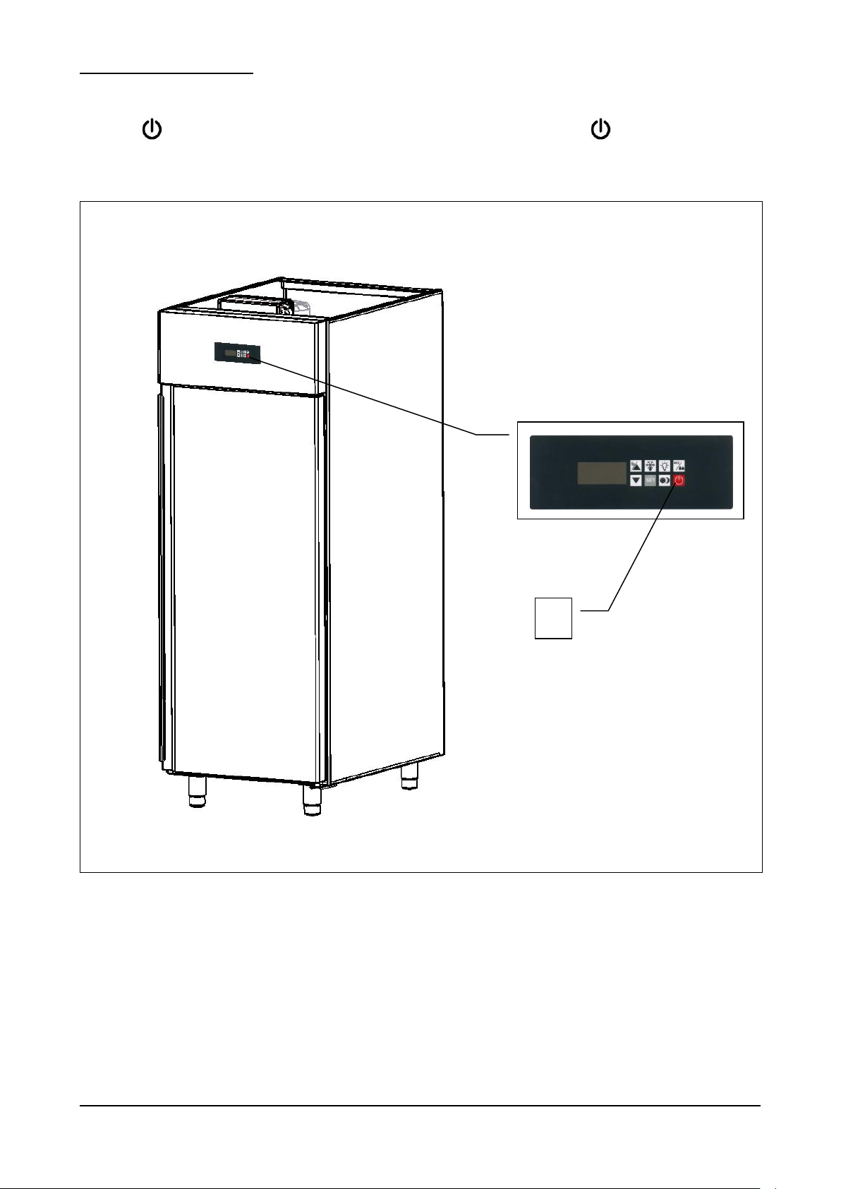
Fig. 1
La ringraziamo per aver scelto un nostro armadio EN serie “DELICE”, conservatore per preparati di pasticceria e
gelateria.
Leggere con molta attenzione il presente manuale, mettendolo a disposizione del personale che dovrà installare,
utilizzare ed eseguire la manutenzione dell’apparecchiatura.
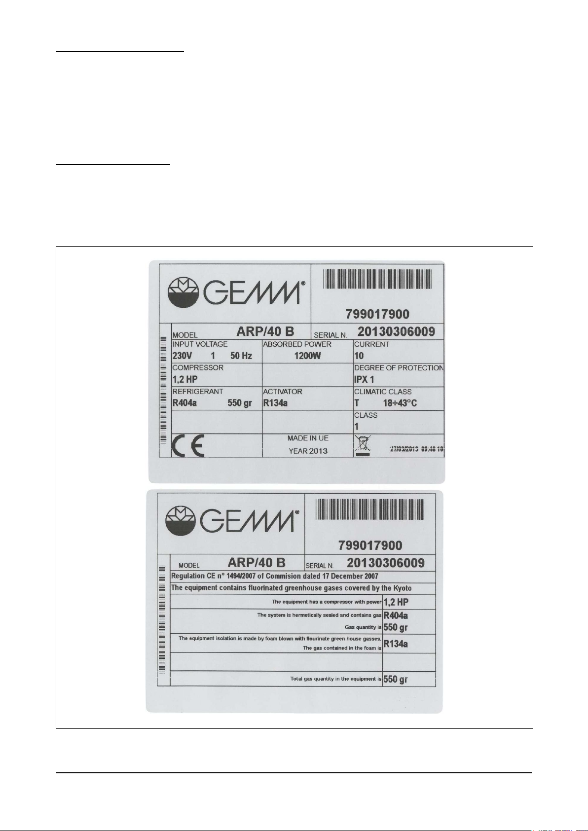
1.1 – DATI DI MARCATURA
In tutti gli armadi EN “Delice”, le targhette di identificazione della macchina (nella fig.1 sotto rappresentate) si trovano
applicate sul fianco dx della scocca, vicino allo spigolo inferiore - anteriore (verso la porta). Questa posizione vale in
entrambi i casi, che l’armadio sia ad 1 o 2 porte.
ARP_ARG Rev03 05-2013 pag. 6
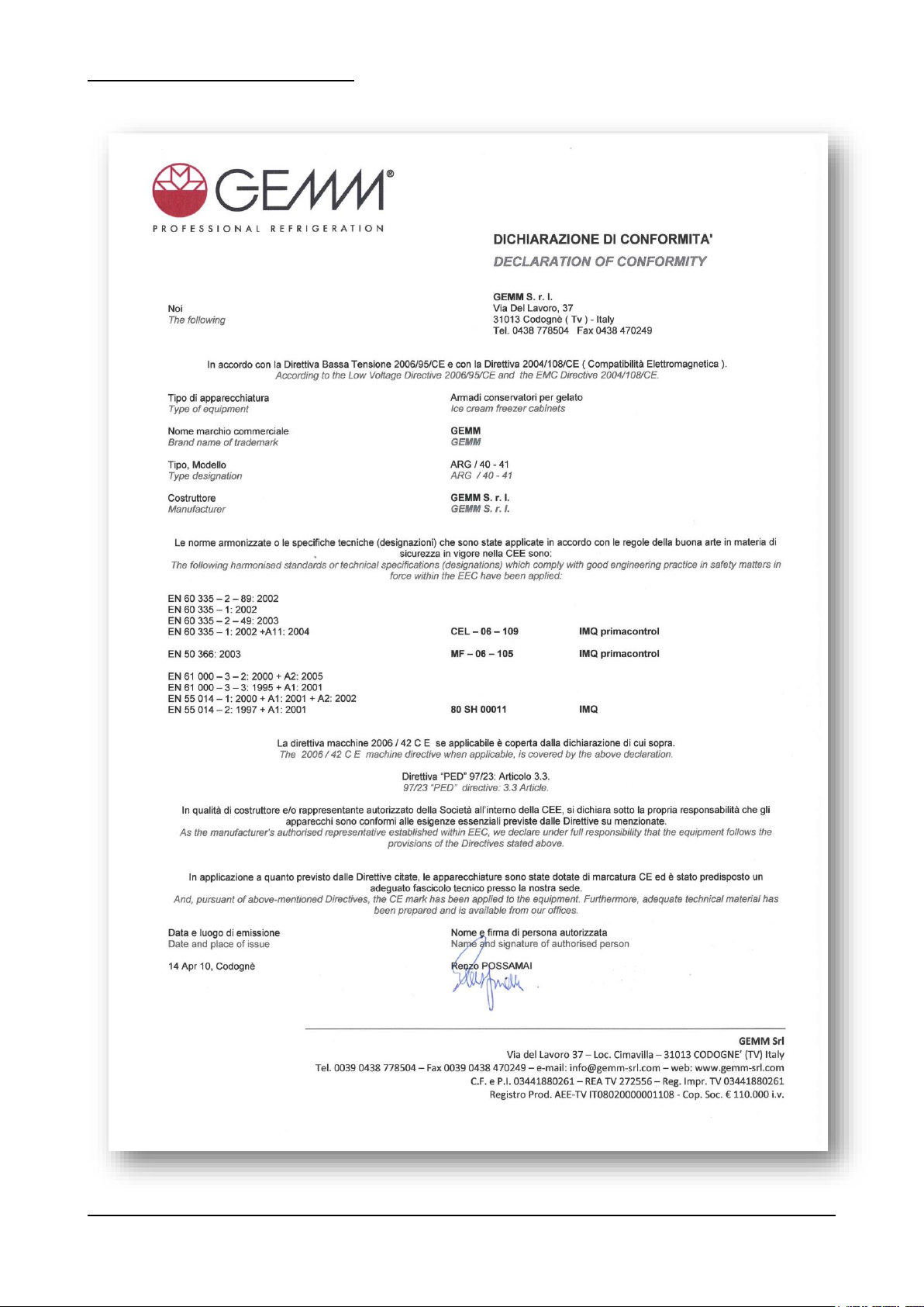
1.2 – DICHIARAZIONE DI CONFORMITA’
ARP_ARG Rev03 05-2013 pag. 7
1.3 – GARANZIA
Questo simbolo contraddistingue informazioni ed avvertenze il cui mancato rispetto può danneggiare
l’apparecchiatura o compromettere la sicurezza del personale.
Questo simbolo contraddistingue informazioni ed avvertenze di carattere elettrico il cui mancato rispetto
può danneggiare l’apparecchiatura o compromettere la sicurezza del personale.
La garanzia sui componenti dell’apparecchiatura, avente decorrenza dalla data riportata sulla relativa bolla di consegna,
è come da contratto di vendita.
Non sono compresi nella garanzia danni all’apparecchiatura causati da:
- trasporto e/o movimentazione;
- errori dell’operatore;
- mancata manutenzione prevista nel presente manuale;
- guasti e/o rotture non imputabili al malfunzionamento dell’apparecchiatura;
- operazioni di manutenzione svolte da personale non qualificato;
- uso improprio.
1.4 – ASSISTENZA
Per qualsiasi necessità inerente l’uso, la manutenzione o la richiesta di parti di ricambio, l’acquirente è pregato di
rivolgersi direttamente al costruttore, specificando i dati identificativi dell’apparecchiatura riportati sulla targhetta di
identificazione.
1.5 – UTILIZZO E CONSERVAZIONE DEL MANUALE
Il presente manuale ha lo scopo di fornire tutte le informazioni necessarie affinché, oltre ad un corretto utilizzo
dell’apparecchiatura, sia possibile gestire la stessa nel modo più autonomo e sicuro possibile.
Il manuale è suddiviso in capitoli, paragrafati e sotto paragrafati: la pagina dell’indice fornisce quindi un modo facile per
trovare qualunque aspetto di interesse.
Il materiale contenuto in questo documento viene fornito esclusivamente per scopi informativi ed è soggetto a modifiche
senza preavviso. Nonostante la massima attenzione riservata alla redazione del documento, la ditta costruttrice non è
responsabile per i danni derivanti da errori od omissioni e dall’utilizzo delle informazioni qui contenute.
Mantenere il presente manuale, e tutta la documentazione allegata, in buono stato, leggibile e completa di tutte le sue
parti; conservarla in prossimità dell’apparecchiatura, in un luogo accessibile e noto a tutti gli operatori.
1.5.1 – SIMBOLI UTILIZZATI NEL PRESENTE MANUALE
ARP_ARG Rev03 05-2013 pag. 8

1.6 – DESCRIZIONE DEL PERSONALE
Gli operatori non devono eseguire operazioni riservate ai manutentori o ai tecnici specializzati.
Il costruttore non risponde di danni derivati dalla mancata osservanza di questo divieto.
Il manuale in oggetto è rivolto sia all’operatore che ai tecnici abilitati all’installazione ed alla manutenzione
dell’apparecchiatura.
- Operatore addetto all’uso dell’apparecchiatura: Personale specializzato in grado di operare con
l’apparecchiatura in condizioni normali attraverso l’uso dei comandi preposti. Deve inoltre essere in grado di
effettuare operazioni semplici di manutenzione ordinaria (pulizia, carico prodotto), avviamento o ripristino
dell’apparecchiatura in seguito ad un’eventuale sosta forzata.
- Tecnico specializzato elettricista: Tecnico specializzato elettricista che ha seguito i corsi di qualifica da parte
del produttore che gli consentono qualsiasi intervento sull’apparecchiatura. Il tecnico specializzato deve essere
in grado di installare l’apparecchiatura e di condurla in condizioni normali; è abilitato a tutti gli interventi di natura
elettrica e meccanica di regolazione, di manutenzione e di riparazione. E’ in grado di operare in presenza di
tensione all’interno di armadi elettrici e scatole di derivazione.
- Tecnico specializzato mulettista: Tecnico specializzato addetto alla movimentazione di materiale all’interno
dell’azienda e munito di patente per l’utilizzo di muletti.
ARP_ARG Rev03 05-2013 pag. 9
2 – DESCRIZIONE DELLA MACCHINA
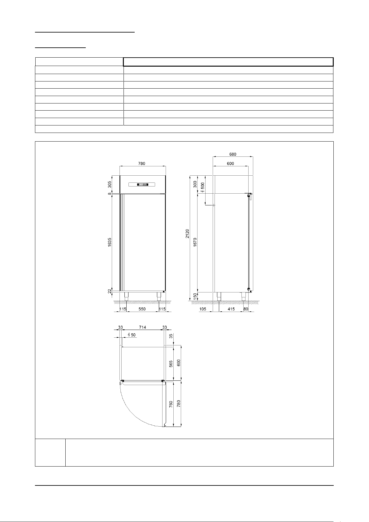
Modello
ARP-20 / ARP-20B
Dimensioni esterne
cm
78 x 68 x 212h
Peso max
kg
119 // 124
Capacità litri
lt
500
Temperatura interna cella
°C
-2 / +8 // -22 / -10
Gas e carica
R 404 a 320gr // 270gr
Potenza refrigerante
W
670 // 610
Potenza max assorbita
W
580 // 750
Tensione di alimentazione
Volt 1x230 ~ 50 Hz
Tab. 1/a
R
Alimentazione elettrica: cavo 3x1.5 mm2 completo di spina Schuko; L=4000 mm
Electricity supply: 3x1.5 mm2 wire complete with Schuko plug; L=4000 mm
Elektrischer Stromanschluss: Kabel 3x1,5 mm2 komplett mit Schukostecker; L=4000 mm
Alimentation électrique: câble 3x1.5 mm2 avec fiche Schuko; L=4000 mm
Fig. 2/a
2.1 – DATI TECNICI
ARP_ARG Rev03 05-2013 pag. 10
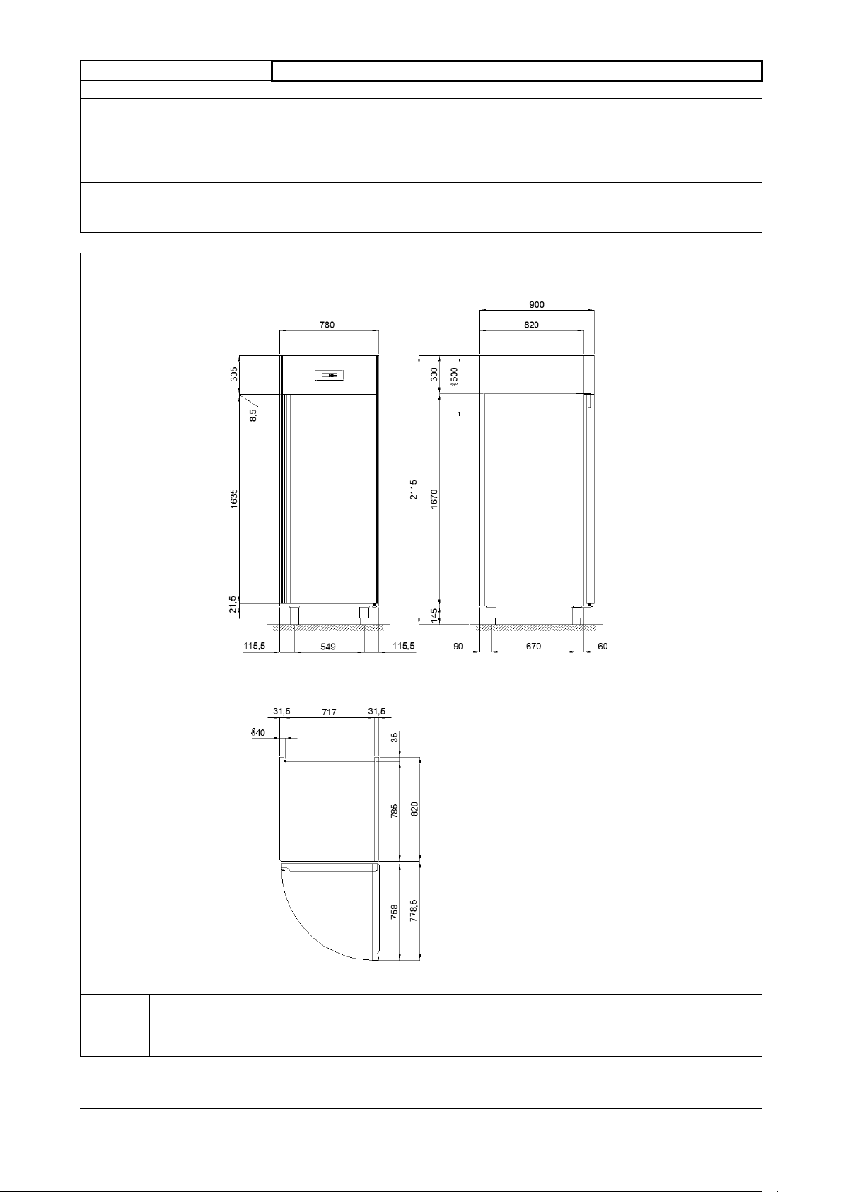
Modello
ARP-30 / ARP-30B
Dimensioni esterne
cm
78 x 90 x 212h
Peso max
kg
140 // 145
Capacità litri
nr
700
Temperatura interna cella
°C
-2 / +8 // -22 / -10
Gas e carica
R 404 a 320gr // 270gr
Potenza refrigerante
W
670 // 610
Potenza max assorbita
W
580 // 750
Tensione di alimentazione
Volt 1x230 ~ 50 Hz
Tab. 1/b
R
Alimentazione elettrica: cavo 3x1.5 mm2 completo di spina Schuko; L=4000 mm
Electricity supply: 3x1.5 mm2 wire complete with Schuko plug; L=4000 mm
Elektrischer Stromanschluss: Kabel 3x1,5 mm2 komplett mit Schukostecker; L=4000 mm
Alimentation électrique: câble 3x1.5 mm2 avec fiche Schuko; L=4000 mm
Fig. 2/b
ARP_ARG Rev03 05-2013 pag. 11
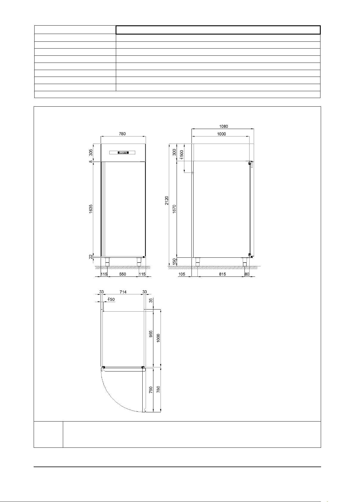
Modello
ARP-40 e ARP-41 (TN) / ARP-40B e ARP-41B e ARG-40 e ARG-41 (BT)
Dimensioni esterne
cm
78 x 108 x 212h
Peso max
kg
186 // 194
Capacità litri
nr
900
Temperatura interna cella
°C
-2 / +8 // -22 / -10 // -25 / -10
Gas e carica
R 404 a 580gr // 550gr
Potenza refrigerante
W
1060 // 860
Potenza max assorbita
W
900 // 990
Tensione di alimentazione
Volt 1x230 ~ 50 Hz
Tab. 1/c
R
Alimentazione elettrica: cavo 3x1.5 mm2 completo di spina Schuko; L=4000 mm
Electricity supply: 3x1.5 mm2 wire complete with Schuko plug; L=4000 mm
Elektrischer Stromanschluss: Kabel 3x1,5 mm2 komplett mit Schukostecker; L=4000 mm
Alimentation électrique: câble 3x1.5 mm2 avec fiche Schuko; L=4000 mm
Fig. 2/c
ARP_ARG Rev03 05-2013 pag. 12
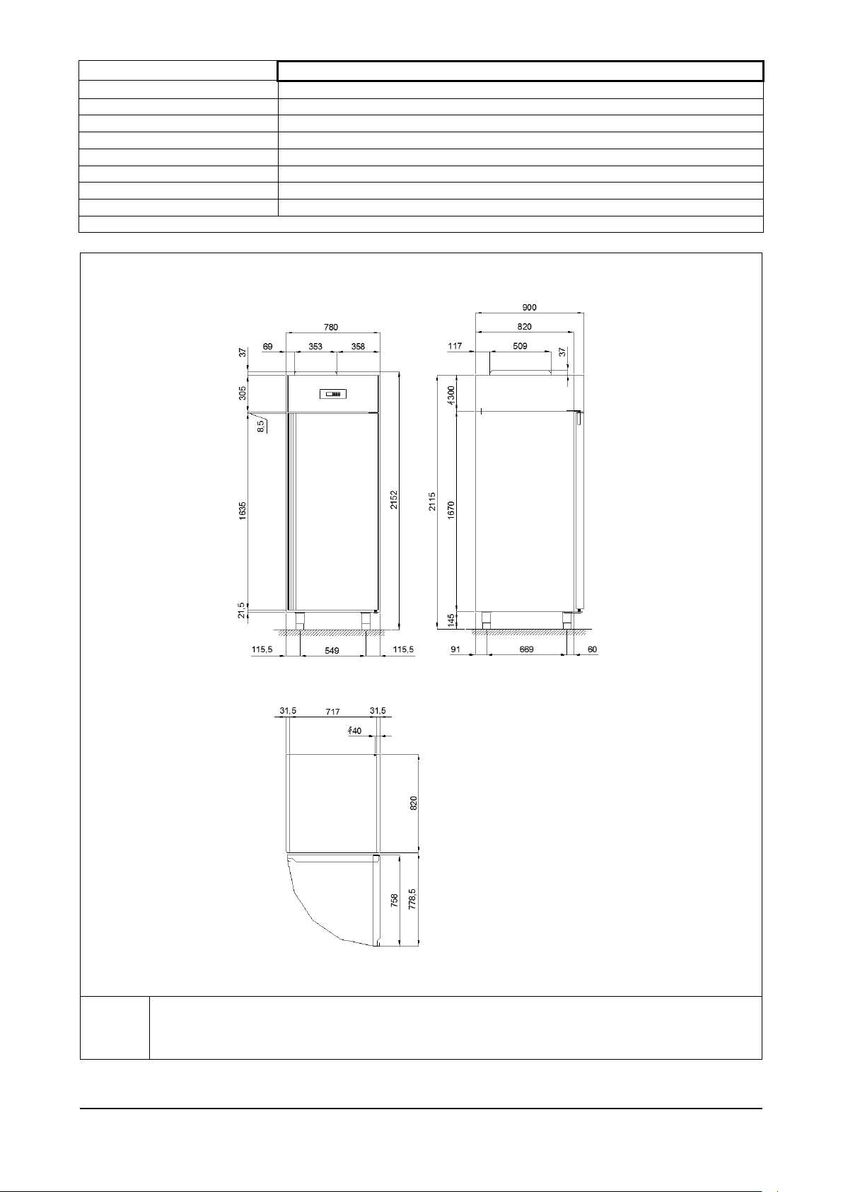
Modello
ARG-30
Dimensioni esterne
cm
78 x 90 x 212h
Peso max
kg
161
Capacità litri
nr
700
Temperatura interna cella
°C
-22 / -10
Gas e carica
R 404 a 400gr
Potenza refrigerante
W
720
Potenza max assorbita
W
740
Tensione di alimentazione
Volt 1x230 ~ 50 Hz
Tab. 1/d
R
Alimentazione elettrica: cavo 3x1.5 mm2 completo di spina Schuko; L=4000 mm
Electricity supply: 3x1.5 mm2 wire complete with Schuko plug; L=4000 mm
Elektrischer Stromanschluss: Kabel 3x1,5 mm2 komplett mit Schukostecker; L=4000 mm
Alimentation électrique: câble 3x1.5 mm2 avec fiche Schuko; L=4000 mm
Fig. 2/d
ARP_ARG Rev03 05-2013 pag. 13
2.2 – DESCRIZIONE DELL’ARMADIO REFRIGERATO EN serie “DELICE” ED USO PREVISTO
Fig. 3
Luogo di installazione
Cucine , laboratori , Ristoranti , sale drink , show-room , bar .
Umidità dell’aria relativa
< 80% con assenza di condensa
Classe climatica
“ST” + 18 °C ÷ + 38 °C
Tab. 2
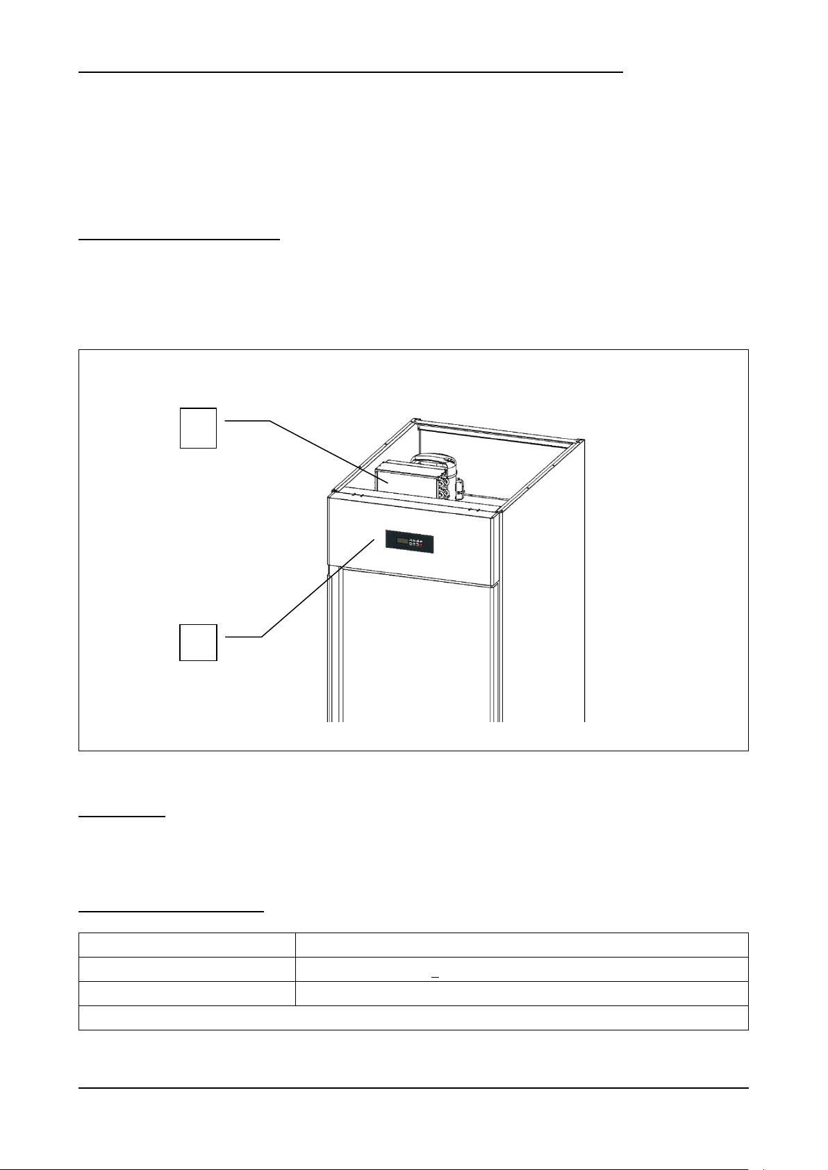
2
1
Gli armadi refrigerati EN della serie “DELICE” sono realizzati in base ai principi di essenzialità e affidabilità.
La struttura è monoscocca, realizzata sia internamente che esternamente in acciaio inox AISI 304 , con isolamento da
70 mm ottenuto mediante iniezione di resine poliuretaniche ad alta densità, esenti HCFC.
Il fondo interno cella è arrotondato per una facile pulizia, i piedini e la struttura reggigriglie sono realizzati in acciaio inox,
la porta è dotata di guarnizione magnetica ad incastro di facile sostituzione , pulizia , e riscaldata nelle versioni BT.
La refrigerazione è ventilata, con controllo tramite teletermostato digitale da retropannello, sbrinamento automatico
elettrico ed evaporazione automatica dell’acqua di condensa.
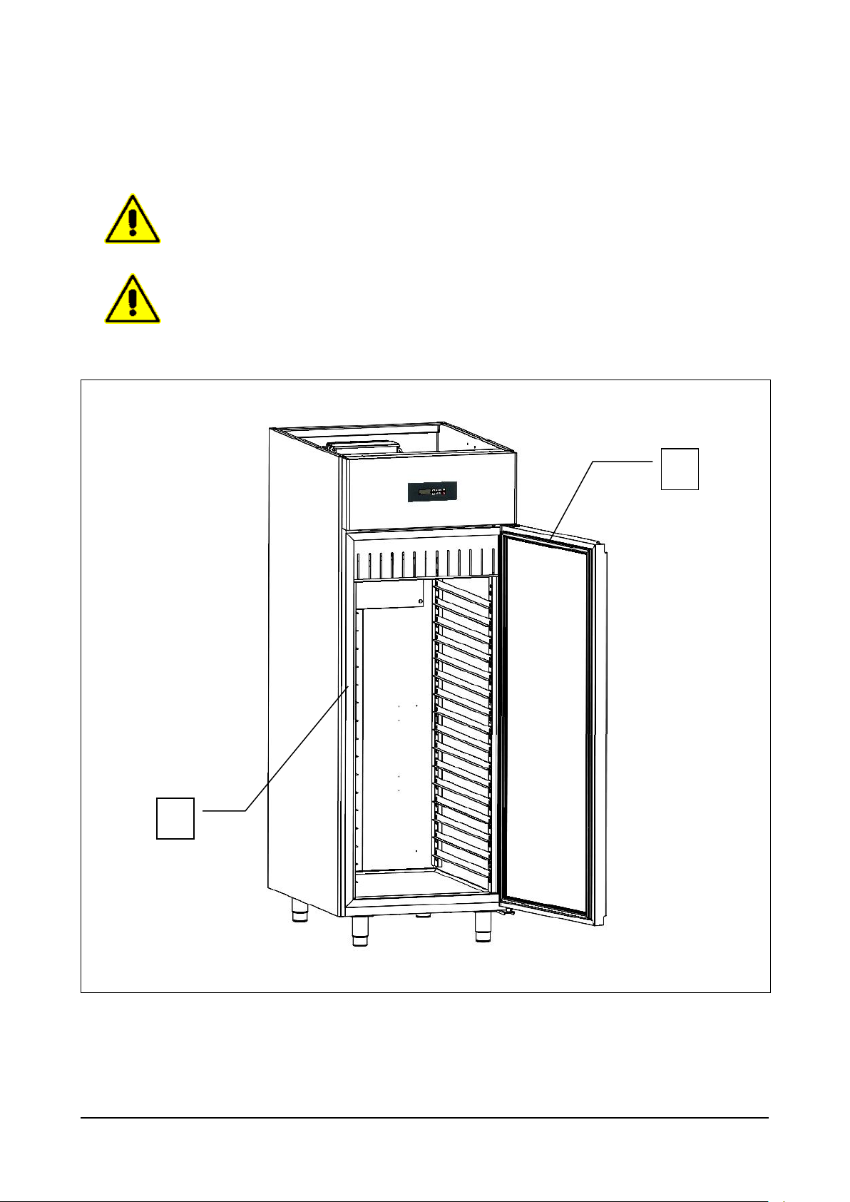
2.2.1 – COMPONENTI PRINCIPALI
L’apparecchiatura è composta dai seguenti componenti:
corpo apparecchiatura;
unità refrigerante monoblocco (rif. 1, fig. 3);
pannello di controllo (rif. 2, fig. 3)
2.3 – RUMORE
L’apparecchiatura è stata progettata e realizzata in modo da ridurre al massimo il livello di potenza acustica.
Nello specifico si dichiara un livello acustico inferiore ai 60 decibel .
2.4 – CONDIZIONI AMBIENTALI
ARP_ARG Rev03 05-2013 pag. 14
3. – SICUREZZA
IMPORTANTE: prima dell’utilizzo dell’apparecchiatura leggere attentamente il presente manuale d’uso e
seguire scrupolosamente le istruzioni tecniche di funzionamento e le indicazioni qui contenute.
L’operatore deve conoscere la posizione e le funzioni di tutti i dispositivi di controllo e le caratteristiche
dell’armadio refrigerato.
L’armadio refrigerato è conforme alle vigenti norme di sicurezza. L’uso improprio può comunque
provocare danni a persone o cose.
All’atto dell’installazione tutto il personale operativo deve essere opportunamente istruito sui rischi di
incidente, i dispositivi di sicurezza per l’operatore, le norme generali di prevenzione degli incidenti
previste dalle direttive internazionali e dalla legge vigente nel paese di utilizzo dell’apparecchiatura.
L’avvio e l’uso dell’apparecchiatura devono essere affidati esclusivamente a personale addestrato. Il
comportamento del personale operativo deve in ogni caso rispettare scrupolosamente le norme sulle
prevenzione degli incidenti vigenti nel paese di utilizzo dell’apparecchiatura.
Non rimuovere o alterare le targhe apposte dal costruttore sull’apparecchiatura.
L’armadio refrigerato non deve essere messo in funzione in caso di difetti al pannello di controllo o parti
danneggiate.
Non ostruire i condotti di aerazione superiori e/o interni dell’apparecchiatura; non riporre il prodotto a
ridosso delle griglie di ventilazione, dei condotti di aerazione, o direttamente sul fondo della cella.
Segnalare tempestivamente eventuali anomalie di funzionamento.
Usare solamente accessori raccomandati dal costruttore.
Non esporre l’apparecchiatura a pioggia o a getti d’acqua
Le operazioni di manutenzione ordinaria e straordinaria che prevedono l’apertura del quadro elettrico
oppure uno smontaggio anche parziale dell’armadio refrigerato, devono essere effettuate solo dopo aver
interrotto l’alimentazione dell’apparecchiatura.
3.1 – AVVERTENZE GENERALI
Il produttore è sollevato da qualunque responsabilità nei seguenti casi:
mancata effettuazione della manutenzione programmata;
modifiche e/o interventi non autorizzati:
utilizzo di ricambi non originali;
mancato o parziale rispetto di quanto riportato nel presente manuale;
uso improprio dell’apparecchiatura.
Qualunque manomissione o sostituzione non autorizzata di una o più parti o componenti dell’apparecchiatura,
l’utilizzo di accessori e materiale di consumo diversi dagli originali, possono rappresentare un rischio di
incidente e sollevano il costruttore da qualunque responsabilità civile o penale.
In caso di dubbio relativamente al funzionamento dell’apparecchiatura, non usarla e contattare il costruttore.
ARP_ARG Rev03 05-2013 pag. 15
3.2 – CONTROINDICAZIONI D’USO
Fig. 4
2
1
1
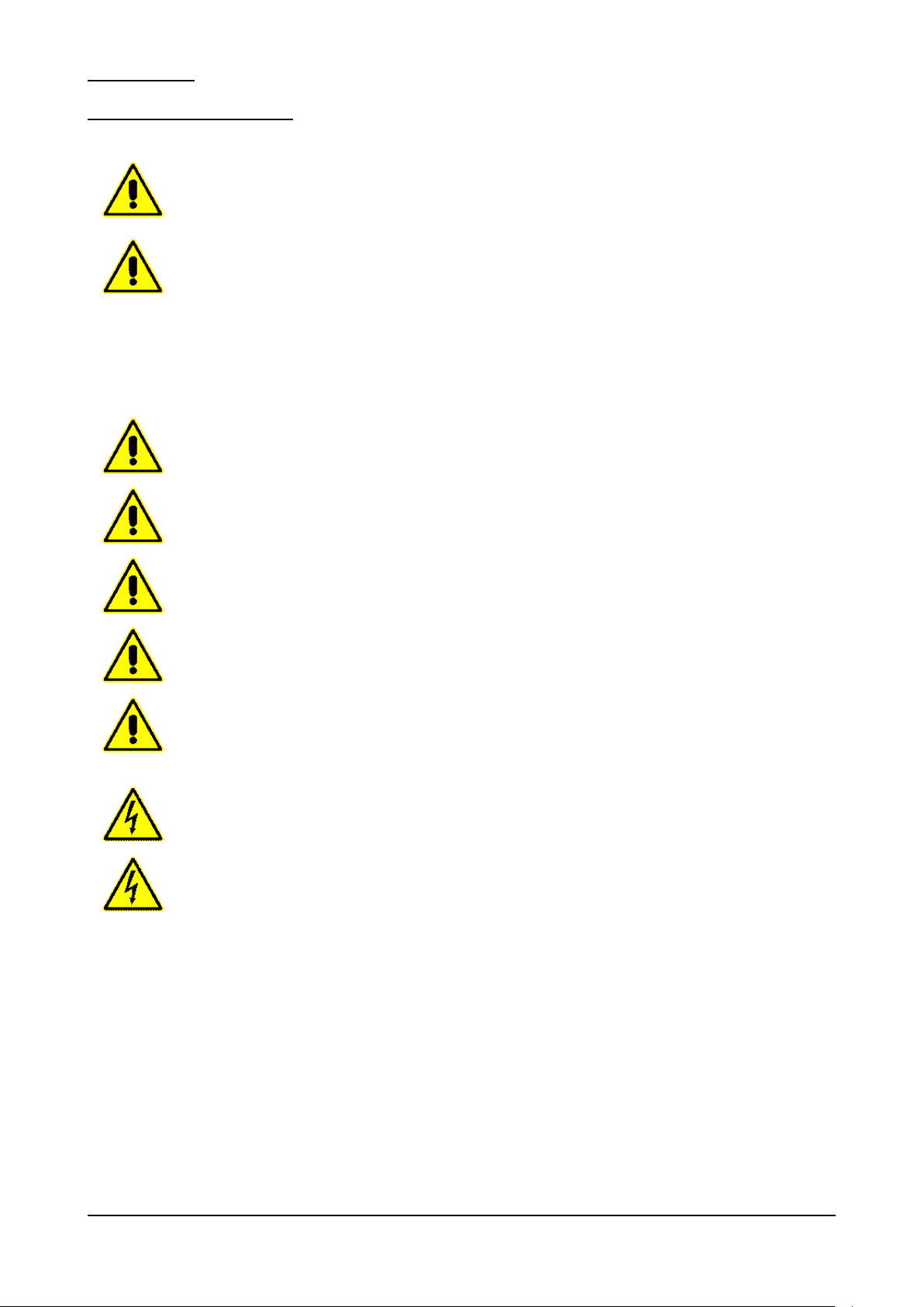
L’armadio refrigerato EN serie “DELICE” non deve essere utilizzato:
per utilizzi diversi da quelli riportati nel paragrafo 2.2 “Descrizione dell’armadio refrigerato ed uso previsto”;
con sistemi di sicurezza non funzionanti;
dopo un’installazione non eseguita correttamente;
da personale non addestrato;
con interventi di manutenzione non eseguiti o eseguiti in modo scorretto;
con utilizzo di ricambi non originali;
con cavo di alimentazione e/o presa elettrica danneggiati;
con condotti di aerazione (rif. 1, fig. 4) ostruiti;
con prodotti alimentari vari (cibi e bevande) posti a ridosso delle griglie di ventilazione interne (rif. 1, fig. 4), o
direttamente sul fondo della cella (rif. 2, fig. 4).
ARP_ARG Rev03 05-2013 pag. 16
3.3 – DISPOSITIVI DI PROTEZIONE
Fig. 5
2
1
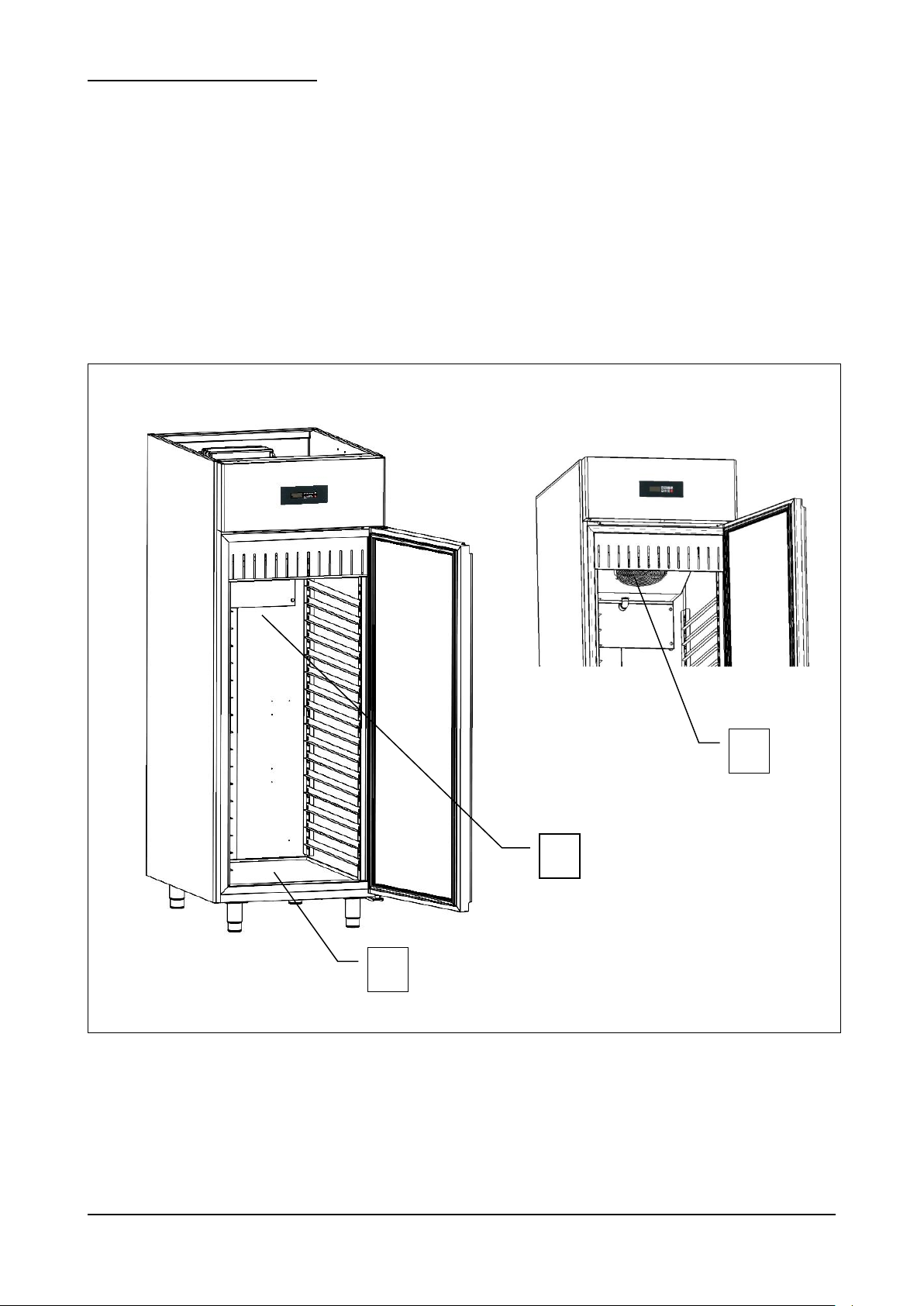
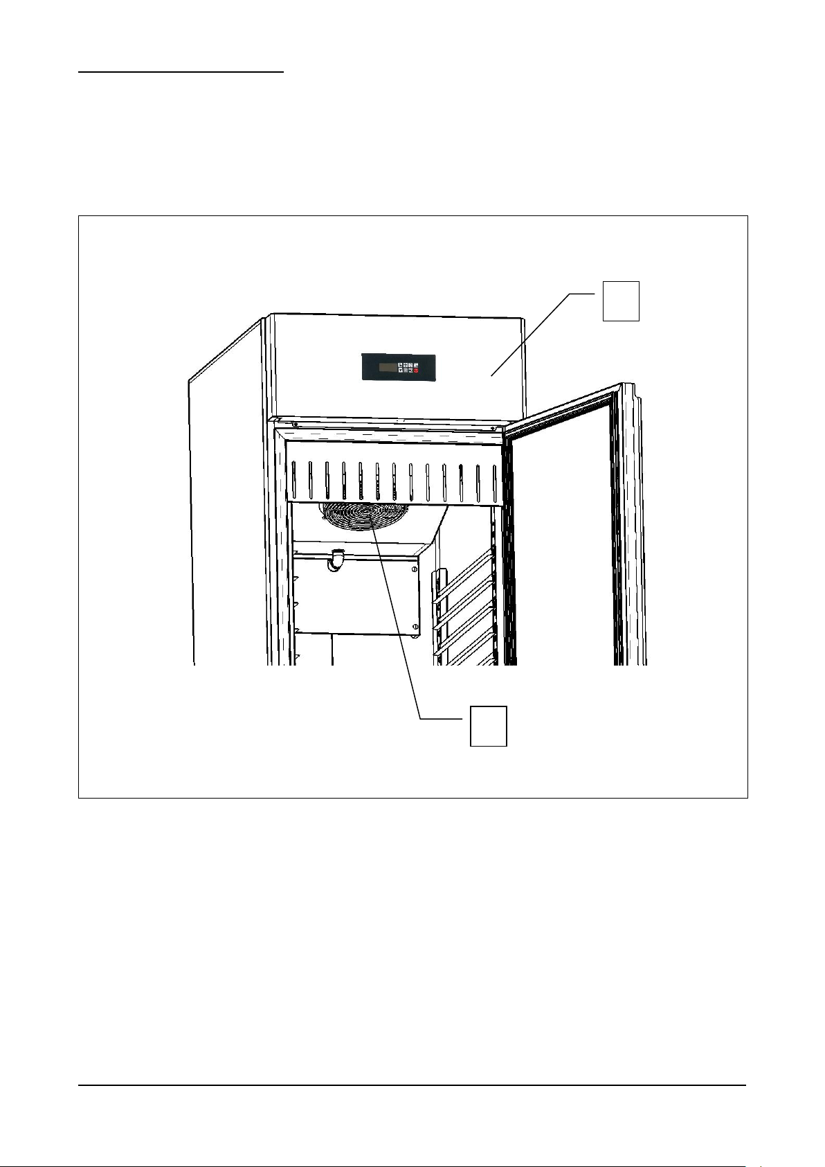
La protezione del personale esposto ai rischi, dovuti agli elementi mobili pericolosi, è garantita dalla presenza di
opportuni dispositivi presenti sull’apparecchiatura:
griglia interna a copertura dell’unità condensatrice (rif. 1, fig. 5);
pannello frontale a copertura della ventola di raffreddamento unità tampone (rif. 2, fig. 5).
ARP_ARG Rev03 05-2013 pag. 17
3.4 – FUNZIONI DI ARRESTO
Fig. 6
1
L' apparecchiatura nel suo complesso è controllata da un teletermostato digitale. La funzione di arresto è rappresentata
dal tasto (rif. 1 fig. 6). In qualsiasi stato si trovi la macchina , la pressione del tasto mette la scheda in OFF.
ARP_ARG Rev03 05-2013 pag. 18
4 – TRASPORTO E MOVIMENTAZIONE
L’apparecchiatura non deve essere assolutamente capovolta.
L’imballo deve essere ben posizionato sul pianale del mezzo di trasporto e bloccato attraverso
l’utilizzo di funi appropriate.
E’ necessario prestare la massima attenzione durante tutte le fasi di sollevamento e
posizionamento dell’armadio, in modo da evitare danni, anche gravi, a persone o cose. Il
costruttore non si assume alcuna responsabilità per il mancato rispetto delle indicazioni
riportate per il sollevamento e il trasporto dell’armadio.
Durante la fase di trasporto la temperatura ambientale non deve mai scendere al di sotto dei 4°C.
Prestare attenzione durante le fasi di sollevamento e movimentazione dell’armadio; esiste il
pericolo di lesioni anche mortali contro il carico in movimento.
Tutte le operazioni di movimentazione e sollevamento devono essere effettuate con la massima
cautela, controllando che tutto il personale sia rigorosamente a distanza di sicurezza, e che
nessuno sosti sotto carichi sospesi, fermi o in movimento.
Prima di iniziare l’operazione, controllare tutta l’area di movimentazione dell’apparecchiatura, in
modo da rilevare l’eventuale presenza di punti pericolosi.
Durante la fase di trasporto la temperatura ambientale non dove mai scendere al di sotto del 4°C.
4.1 – TRASPORTO DELL’ARMADIO REFRIGERATO
In funzione della tipologia e delle dimensioni e pesi sono stati utilizzati imballi adeguati a garantire l’integrità e la
conservazione durante il trasporto fino alla consegna all’acquirente.
L’armadio refrigerato deve essere posizionato e mantenuto in piedi su bancale avvolto dal proprio cartone per tutta la
durata del trasporto.
L’armadio refrigerato viene fornito al trasportatore pronto per lo spostamento.
Il materiale d’imballo, una volta disimballato l’armadio refrigerato, dovrà essere eliminato e/o riutilizzato secondo le
norme vigenti del Paese di destinazione dell’apparecchiatura.
4.2. – MOVIMENTAZIONE DELL’ARMADIO REFRIGERATO IMBALLATO
ARP_ARG Rev03 05-2013 pag. 19
PERSONALE AUTORIZZATO
Modello
ARP-20 / ARP-20B
ARP-30 / ARP-30B
ARP-40 / ARP-40B
ARG-30
Dimensioni
cm
78 x 68 x 212h
78 x 90 x 212h
78 x 108 x 212h
78 x 90 x 212h
Peso
Kg
119 / 124
140 / 145
186 / 194
161
Tab.3
L’impiego di attrezzature non adeguate può comportare incidenti al personale impiegato
nell’operazione e/o danni all’apparecchiatura.
Il costruttore non si assume alcuna responsabilità per l’uso improprio e non conforme di
apparecchi per il sollevamento, il trasporto e la movimentazione.
Tecnico specializzato mulettista.
Mezzi di protezione individuali:
- scarpe antinfortunistiche;
- guanti antinfortunistici.
Il personale addetto a tali operazioni non deve utilizzare anelli, orologi da polso, gioielli, capi di vestiario slacciati o sciolti,
quali ad esempio cravatte, indumenti strappati, sciarpe, giacche sbottonate o bluse con chiusure a lampo aperte ecc… In
generale il personale deve usare capi ad uso antinfortunistico.
4.2.1 – PESO E INGOMBRO DELL’ARMADIO REFRIGERATO
4.2.2 – MEZZI NECESSARI
- Per il sollevamento dell’apparecchiatura deve essere utilizzato un muletto con portata minima adeguata.
ARP_ARG Rev03 05-2013 pag. 20
5 – INSTALLAZIONE
Prestare la massima cautela nel maneggiare l’apparecchiatura, in modo da evitare danni alle cose o alle
persone.
L’apparecchiatura non deve essere messa in funzione in caso di difetti al pannello di controllo o parti
danneggiate.
Verificare che l’imballo non sia stato danneggiato durante il trasporto.
L’impiego di attrezzature non adeguate può comportare incidenti al personale impiegato
nell’operazione e/o danni all’apparecchiatura.
Il costruttore non si assume alcuna responsabilità per l’uso improprio e non conforme di
apparecchi per il sollevamento, il trasporto e la movimentazione.
PERSONALE AUTORIZZATO
Tecnico specializzato elettricista.
Mezzi di protezione individuali:
scarpe antinfortunistiche;
guanti antinfortunistici.
Il personale addetto a tali operazioni non deve utilizzare anelli, orologi da polso, gioielli, capi di vestiario slacciati o sciolti,
quali ad esempio cravatte, indumenti strappati, sciarpe, giacche sbottonate o bluse con chiusure a lampo aperte ecc… In
generale il personale deve usare capi ad uso antinfortunistico.
5.1 – PREDISPOSIZIONE ALL’INSTALLAZIONE
Per l’installazione occorre predisporre un’area di manovra adeguata alle dimensioni dell’apparecchiatura (vedi fig. 2) e
dei mezzi di sollevamento prescelti.
Il luogo di installazione dovrà essere predisposto di tutta l’impiantistica di collegamento necessaria alla messa in
funzione dell’apparecchiatura.
Il luogo scelto per l’installazione deve avere requisiti idonei a permettere l’utilizzazione dell’apparecchiatura in condizioni
di sicurezza. La zona deve essere tale da garantire una buona base di appoggio, con pavimentazione solida, livellata e
con finitura tale da garantire un’adeguata e sicura operatività del personale.
Il luogo d’installazione deve presentare un’illuminazione, naturale e/o artificiale, adeguata alle operazioni da svolgere (in
base alle norme specifiche).
5.2 – DISIMBALLAGGIO
5.2.1 – MEZZI NECESSARI
Per il sollevamento dell’apparecchiatura deve essere utilizzato un muletto o un’attrezzatura equivalente.
ARP_ARG Rev03 05-2013 pag. 21
5.2.2 – PROCEDURA DI DISIMBALLAGGIO
Tutte le operazioni di movimentazione e disimballaggio devono essere effettuate con la massima
cautela, controllando che tutto il personale sia rigorosamente a distanza di sicurezza, e che
nessuno sosti sotto carichi sospesi, fermi o in movimento.
DOPO LA FASE DI INSTALLAZIONE DELL’APPARECCHIATURA, ATTENDERE ALMENO DUE
ORE PRIMA DI PROCEDERE ALL’ACCENSIONE DI ESSA.
L’impiego di attrezzature non adeguate può comportare incidenti al personale impiegato
nell’operazione e/o danni all’apparecchiatura.
Il costruttore non si assume alcuna responsabilità per l’uso improprio e non conforme di
apparecchi per il sollevamento, il trasporto e la movimentazione.
Tutte le operazioni di movimentazione e disimballaggio devono essere effettuate con la massima
cautela, controllando che tutto il personale sia rigorosamente a distanza di sicurezza, e che
nessuno sosti sotto carichi sospesi, fermi o in movimento.
Per disimballare l’apparecchiatura è sufficiente togliere il cartone posto attorno ad essa. Procedere, successivamente, a
far scendere l’apparecchiatura dal bancale, sollevandola attraverso l’utilizzo di un apposito muletto; le forche del muletto
vanno poste sotto all’apparecchiatura.
5.3 – MOVIMENTAZIONE DELL’ARMADIO REFRIGERATO
5.3.1 – MEZZI NECESSARI
Vedi paragrafo 5.2.1.
5.3.2 – PROCEDURA DI MOVIMENTAZIONE DELL’ARMADIO DISIMBALLATO
Per movimentare l’armadio, procedere al sollevamento attraverso l’utilizzo di un apposito muletto; le forche del muletto
vanno poste sotto all’apparecchiatura.
5.4 – MONTAGGIO DELL’ARMADIO
Il cliente riceve l’armadio refrigerato EN serie “DELICE”, montato in tutte le sue parti.
ARP_ARG Rev03 05-2013 pag. 22
6 – MESSA IN OPERA
DOPO LA FASE DI INSTALLAZIONE DELL’APPARECCHIATURA, ATTENDERE ALMENO DUE
ORE PRIMA DI PROCEDERE ALL’ACCENSIONE DELLA STESSA.
Il collegamento elettrico deve essere effettuato da un tecnico specializzato elettricista.
Controllare che la tensione di alimentazione indicata sulla targhetta di identificazione
corrisponda a quella disponibile sulla rete elettrica del luogo di installazione.
L’impianto deve essere eseguito secondo le norme vigenti; le rete di alimentazione deve avere
un efficiente impianto di terra secondo le normative elettriche esistenti nel paese; questa
responsabilità è a carico del cliente.
Non provocare piegature strette sul cavo di alimentazione e non appoggiarvi sopra oggetti di
qualsiasi natura.
Nel caso in cui fosse necessario staccare la spina di alimentazione, assicurarsi prima che la
scheda , mediante il tasto , sia posizionata su OFF sul display.
Il costruttore declina ogni responsabilità per danni o incidenti causati dall’inosservanza di dette
norme.
Interventi di regolazione eseguiti da personale non autorizzato possono danneggiare
l’apparecchiatura ed esporre l’operatore a seri pericoli. Interventi di regolazione eseguiti da
personale non autorizzato sono considerati manomissioni dell’apparecchiatura e come tali ne
fanno decadere la garanzia e sollevano il costruttore da qualunque responsabilità.
6.1 – COLLEGAMENTI
6.1.1 – COLLEGAMENTO ELETTRICO
PROCEDURA DI COLLEGAMENTO ELETTRICO
L’apparecchiatura viene fornita dal costruttore completa di spina di alimentazione. E’ sufficiente collegare la spina di
alimentazione ad una presa di corrente dell’impianto del luogo di installazione; l’impianto deve essere eseguito secondo
le norme vigenti.
L’energia elettrica del luogo d’installazione deve avere i seguenti requisiti:
Tensione: 230 Vac
Frequenza: 50 Hz
6.2 – CONTROLLI PRELIMINARI
L’installatore elettricista dovrà istruire l’operatore sull’utilizzo corretto dell’armadio refrigerato e trasmettere le nozioni
basilari di manutenzione.
MODALITA’
Le operazioni di preparazione dell’armadio refrigerato per il primo avviamento, devono essere eseguite da un tecnico
specializzato, in presenza dell’operatore addetto all’uso dell’apparecchiatura che avrà così la possibilità di acquisire un
minimo di informazioni atte a svolgere successivamente l’attività di manutenzione ordinaria consentita e di pulizia.
Prima della messa in funzione dell’apparecchiatura, è necessario eseguire una serie di verifiche e controlli allo scopo di
prevenire errori od incidenti durante la fase di messa in funzione.
Verificare che l’apparecchiatura non abbia subito danni durante la fase di trasporto.
Verificare , con particolare cura, l’integrità del quadro elettrico, pulsantiera di comando, cavi elettrici e tubazioni.
Controllare l’esatto collegamento di tutte le fonti di energia esterne.
Controllare il corretto livellamento della macchina.
6.2.1 – REGOLAZIONI
ARP_ARG Rev03 05-2013 pag. 23
7 – USO
DOPO LA FASE DI INSTALLAZIONE DELL’APPARECCHIATURA, ATTENDERE ALMENO DUE
ORE PRIMA DI PROCEDERE ALL’ACCENSIONE DELLA STESSA.
Fig. 7
7.1 – USO PREVISTO
La serie “Delice” è sinonima di armadi refrigerati e conservatori per la pasticceria e gelateria professionale estremamente
semplici ed affidabili. Costruiti completamente in acciaio secondo adeguati standard qualitativi, sono dotati di isolamento
da 70mm ottenuto con iniezione di resine poliuretaniche esenti HCFC. Sono controllati da un teletermostato digitale da
retropannello di facile lettura e programmazione. La refrigerazione è ventilata, lo sbrinamento è automatico con
dispositivo per l’eliminazione automatica dell’acqua di condensa.
7.2 – USI NON PREVISTI
Non sono previsti per l’armadio refrigerato utilizzi diversi da quelli descritti al punto 7.1. In particolare l’armadio non è
un’apparecchiatura adatta al raffreddamento rapido di prodotti alimentari vari, cibi e/o bevande.
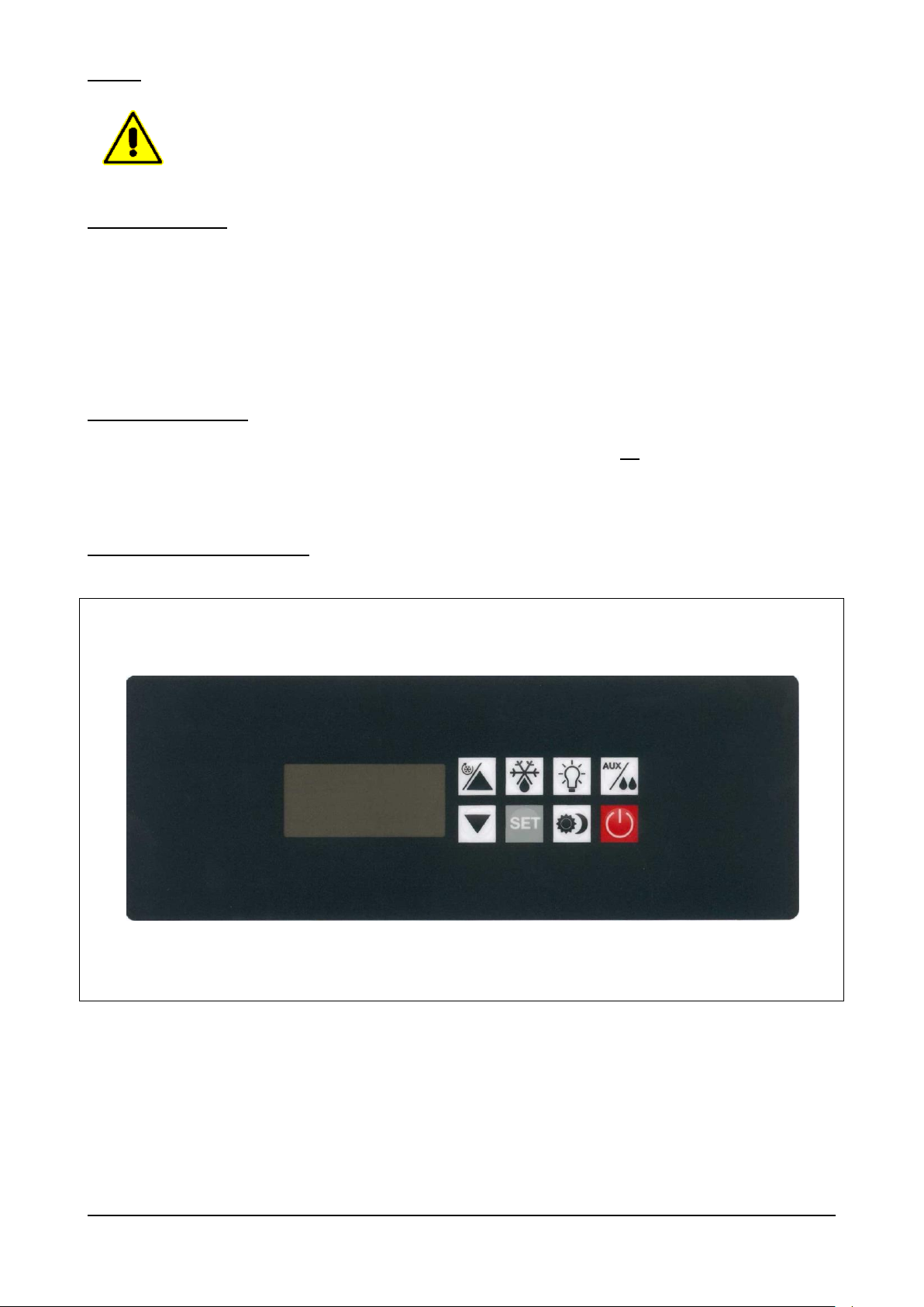
7.3 – PANNELLO DI CONTROLLO
ARP_ARG Rev03 05-2013 pag. 24
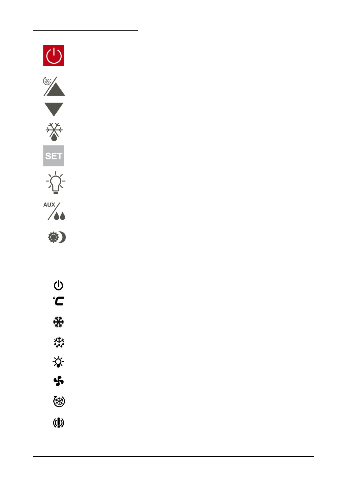
I tasti presenti sul controllore sono i seguenti:
TASTO 0/1, ON-OFF
Con macchina in OFF (0) la singola pressione permette di
passare allo stato di ACCESA (1).
Mentre la vetrina è accesa , dopo aver attivato la tastiera
premendo per 3sec qualsiasi tasto, la singola pressione mette la
scheda in OFF.
TASTI PIU’ E MENO
Permettono di incrementare o diminuire il valore che appare sul
display. A tastiera attiva, la pressione continua per 3sec del tasto
freccia SU permette di attivare il ciclo continuo a tempo.
TASTO DEFROST
Con la macchina ACCESA la pressione continua per 3sec
permette di effettuare lo sbrinamento.
TASTO SET
Con la macchina ACCESA, a tastiera attiva, la singola pressione
permette di visualizzare il set point, la pressione continua per 3
sec permette di modificare il set point.
TASTO LUCE
Con la macchina ACCESA, a tastiera attiva, la singola pressione
permette di accendere o spegnere la luce interno cella .
TASTO AUX / DOPPIA HR
Con la macchina ACCESA, a tastiera attiva, la singola pressione
permette di attivare , nella vers. TN , la funzione doppia umidità in
cella .
TASTO ENERGY SAVING
Con la macchina ACCESA, a tastiera attiva, la pressione continua
per 3sec. permette di attivare o disattivare la funzione "notturna"
di energy saving .
OFF
E’ accesa quando la macchina si trova nello stato di OFF ed è
spenta in tutti gli altri casi.
CELSIUS
Può essere accesa ed indicare l’unità di misura della temperatura.
COMPRESSORE
E’ accesa durante le fasi normali di refrigerazione, compressore
ON, spenta con compressore OFF. E’ lampeggiante durante la
fase di sgocciolamento del defrost.
DEFROST
E’ accesa durante una fase di DEFROST.
LUCE
E’ accesa solo quando sono accese le luci interno cella.
VENTOLE
E’ accesa solo quando sono in funzione le ventole interno cella
(Evaporatore).
CICLO CONTINUO
E’ accesa solo quando viene attivato il ciclo continuo (ciclo a
tempo).
ALLARMI
E’ accesa solo quando viene registrato, dalla centralina, un
allarme e/o un malfunzionamento dell’apparecchiatura.
Le icone presenti sul display del controllore sono:
ARP_ARG Rev03 05-2013 pag. 25
7.4 – PROCEDURE PER IL CONTROLLO
L' apparecchiatura nel suo complesso è controllata da un teletermostato digitale da retropannello.
Nel momento in cui la macchina viene alimentata elettricamente il display dell’apparecchiatura si illumina completamente
per un “lamp-test” di alcuni secondi al termine del quale si riporta nello stato in cui si trovava prima che l’alimentazione
fosse tolta. In particolare se era in corso un ciclo questo riprenderà dove è stato interrotto.
Con scheda in OFF il display è completamente spento ad eccezione dell’icona . Con la pressione del tasto il
display spegne l’icona e si porta in ACCESA visualizzando la temperatura presente in cella.
Utilizzando i comandi posti sul teletermostato ed aiutandosi con le indicazioni del display è possibile attivare le diverse
funzioni della macchina.
E’ possibile tacitare la segnalazione acustica, di qualsiasi origine essa sia, premendo un tasto qualsiasi.
In qualsiasi stato si trovi la macchina, la pressione del tasto mette la scheda in OFF.
7.5 – PROCEDURE PER L’UTILIZZO
Prima di utilizzare la macchina è opportuno eseguire un’accurata pulizia all’interno della cella.
E’ buona norma dopo l’installazione o dopo un lungo periodo di inutilizzo far lavorare l’apparecchiatura a vuoto fino al
raggiungimento della temperatura impostata.
Per ottenere una buona resa dell’armadio refrigerato si consiglia di sistemare il prodotto in modo da favorire la
circolazione dell’aria: non ostruire l’aspirazione del gruppo frigorifero, non sovrapporre prodotti e preparati, distribuire in
maniera ordinata il carico.
Per non avere forti rallentamenti nella resa del gruppo frigo, si consiglia di non sovraccaricare la macchina oltre le
quantità consentite, di non introdurre prodotti quali prodotti e/o preparati con una temperatura superiore a quella
dell’ambiente indicato di progetto e di evitare inutili aperture porta.
ARP_ARG Rev03 05-2013 pag. 26
7.6 – UTILIZZI
- Con il tasto , è possibile visualizzare il set-point e modificarlo se necessario.
con la pressione singola del tasto viene solo visualizzata la temperatura impostata, con la pressione
per 3sec dello stesso tasto questo valore, con le frecce su e giù, è anche modificabile.
- E’ possibile selezionare una fase di defrost manuale; con la pressione per 3sec del tasto se la temperatura
dell’evaporatore non è superiore ai +8°C, viene attivata una fase di defrost manuale. Questa fase termina o a
tempo trascorsi 30’ o a temperatura rilevata dalla sonda all’evaporatore (+8°C). Il defrost automatico, gestito dal
teletermostato, avviene ogni 6H sempre con una durata max di 30’ ed è segnalato a display dalla scritta dEF .
- Con la pressione singola dei tasti e è possibile visualizzare rispettivamente la temperatura
massima e la temperatura minima registrate dalla sonda interno cella. I valori visualizzati vengono preceduti
rispettivamente dalle scritte LO e HY . Nel momento della visualizzazione, con la pressione per 3sec del tasto
è possibile resettare questo valore memorizzato. Questa operazione è preceduta dalla scritta RST
(reset) .
7.6.1 – UTILIZZI PARTICOLARI
- Con la pressione per 3sec del tasto è possibile attivare la fase CICLO CONTINUO . Questa fase è
contraddistinta da una durata (1H) e una temperatura ( -2°C (TN) e -25°C (BT) ) valori impostati dal costruttore
nella centralina. Inoltre per differenziarsi da una normale fase frigorifera, il simbolo a display è acceso.
Una volta trascorso il tempo (1H) impostato, il simbolo si spegnerà e l’apparecchiatura riprenderà a funzionare
con il precedente set point impostato.
7.6.2 – ARRESTO PER LUNGHI PERIODI
Mettere la macchina in OFF , a tastiera attiva, premendo il tasto e scollegare la spina.
Procedere ad una approfondita pulizia della macchina (come da paragrafo 8.2) e assicurarsi di lasciare la porta aperta
al termine dell’operazione e per tutto il periodo di inattività.
ARP_ARG Rev03 05-2013 pag. 27
8 – MANUTENZIONE
Il costruttore deve essere contattato per qualunque anomalia non descritta nel presente manuale; il
costruttore deve essere contattato anche per qualsiasi dubbio riscontrato durante le operazioni di
manutenzione qui descritte. Interventi di manutenzione eseguiti da personale non autorizzato
possono danneggiare l’apparecchiatura ed esporre l’operatore a seri pericoli. Interventi di
manutenzione eseguiti da personale non autorizzato sono considerati manomissioni all’apparecchio
e come tali ne fanno decadere la garanzia e sollevano il costruttore da qualunque responsabilità.
Qualsiasi operazione di manutenzione ordinaria o straordinaria che preveda l’apertura del
quadro elettrico oppure uno smontaggio anche parziale della macchina deve essere
effettuata solo dopo che l’apparecchiatura è stata spenta, sul display, e che la spina è
stata scollegata.
Qualsiasi operazione di manutenzione effettuata sulla macchina con l’impianto elettrico sotto
tensione può provocare gravi incidenti, anche mortali, alle persone.
La disattivazione dei dispositivi di protezione deve essere effettuata solo da personale autorizzato, il
quale provvederà a garantire l’incolumità di persone e ad evitare qualsiasi danno alla macchina.
Dopo aver eseguito la manutenzione necessaria, i dispositivi di protezione devono essere riattivati
correttamente.
Durante le operazioni di manutenzione o riparazione, persone non autorizzate devono tenersi a
distanza dell’apparecchiatura.
Rispettate gli intervalli prescritti o indicati nel presente manuale per l’esecuzione di controlli.
Al termine delle operazioni di manutenzione o riparazione è possibile riavviare l’apparecchiatura solo
dopo che il tecnico specializzato si sia accertato che:
- i lavori siano stati effettuati completamente;
- i sistemi di sicurezza siano attivi;
- l’apparecchiatura funzioni perfettamente;
- nessuno stia operando sull’apparecchiatura.
Componente
Tipo di intervento
Tempificazione
Responsabilità
Modalità
Cella interna
Pulizia
Secondo necessità
Operatore addetto all’uso dell’apparecchiatura
Vedi par. 8.2.2
Parte esterna
Pulizia
Secondo necessità
Operatore addetto all’uso dell’apparecchiatura
Vedi par. 8.2.3
Condensatore
Pulizia
Ogni 60 giorni
Operatore addetto all’uso dell’apparecchiatura
Vedi par. 8.2.4
Tab. 4
8.1 – PRECAUZIONI PARTICOLARI
8.2 – MANUTENZIONE ORDINARIA
8.2.1 – TABELLA RIASSUNTIVA DELLE MANUTENZIONI ORIDNARIE (TAB. 4)
8.2.2 – PULIZIA CELLA INTERNA
Questa operazione deve essere effettuata secondo necessità.
STATO DELL’APPARECCHIATURA:
- pulsante di accensione/spegnimento in posizione OFF sul display;
- spina di alimentazione scollegata dalle rete elettrica.
PERSONALE AUTORIZZATO
Operatore addetto all’uso dell’apparecchiatura.
ARP_ARG Rev03 05-2013 pag. 28
MODALITA’
Per la pulizia dell’apparecchiatura utilizzare solo ed esclusivamente acqua e detergente neutro non
abrasivo. L’utilizzo di prodotti diversi può causare il danneggiamento delle superfici
dell’apparecchiatura e compromettere la qualità e la salubrità del prodotto trattato.
Non utilizzare spugne abrasive.
Non effettuare la pulizia attraverso l’utilizzo di panni che potrebbero rilasciare fibre e non utilizzare
getti d’acqua diretti nell’apparecchiatura.
Fig. 8
1
2
Pulire con estrema cura la parte interna della cella, la superficie di chiusura della porta (rif. 1 fig. 8) e la guarnizione (rif. 2
fig. 8), utilizzando una spugna imbevuta di detergente neutro, entrambi non abrasivi. Terminata la pulizia sciacquare,
attraverso l’utilizzo di una spugna pulita imbevuta d’acqua, e asciugare attraverso l’utilizzo di un panno pulito.
Una corretta pulizia interna dell’apparecchiatura, evita la formazione di cattivi odori che potrebbero danneggiare il
prodotto finale.
ARP_ARG Rev03 05-2013 pag. 29
8.2.3 – PULIZIA PARTE ESTERNA DELL’APPARECCHIATURA
Per la pulizia dell’apparecchiatura utilizzare solo ed esclusivamente acqua e detergente neutro non
abrasivo. L’utilizzo di prodotti diversi può causare il danneggiamento delle superfici
dell’apparecchiatura e compromettere la qualità e la salubrità del prodotto trattato.
Non utilizzare spugne abrasive.
Non effettuare la pulizia attraverso l’utilizzo di panni che potrebbero rilasciare fibre.
Questa operazione deve essere effettuata secondo necessità.
STATO DELL’APPARECCHIATURA:
- pulsante di accensione/spegnimento in posizione OFF sul display;
- spina di alimentazione scollegata dalle rete elettrica.
PERSONALE AUTORIZZATO
Operatore addetto all’uso dell’apparecchiatura.
MODALITA’
Pulire le superfici esterne dell’apparecchiatura (porta fianchi e pannellature in acciaio), utilizzando una spugna imbevuta
di detergente neutro, entrambi non abrasivi. Terminata la pulizia sciacquare, attraverso l’utilizzo di una spugna pulita
imbevuta d’acqua, e asciugare attraverso l’utilizzo di un panno pulito.
ARP_ARG Rev03 05-2013 pag. 30

8.2.4 – PULIZIA CONDENSATORE APPARECCHIATURA
Fig. 9
Il condensatore presenta bordi taglienti. Durante le sopracitate operazioni indossare sempre
guanti protettivi, occhiali e maschere di protezione delle vie respiratorie.
Per la pulizia non utilizzare getti d’acqua diretti nell’apparecchiatura.
1
Questa operazione deve essere effettuata ogni 60 gg.
STATO DELL’APPARECCHIATURA:
- pulsante di accensione/spegnimento in posizione OFF sul display;
- spina di alimentazione scollegata dalle rete elettrica.
PERSONALE AUTORIZZATO
Operatore addetto all’uso dell’apparecchiatura.
MODALITA’
Per un corretto ed efficiente funzionamento dell’apparecchiatura, è necessario che il condensatore ad aria (rif. 1 fig. 9)
sia mantenuto pulito per permettere la libera circolazione dell’aria. Questa operazione è da farsi ogni 60 gg. massimo.
Effettuare la pulizia con spazzole non metalliche in modo da rimuovere tutta la polvere e la lanugine dalle alette. Si
consiglia l’uso di un aspirapolvere per evitare di disperdere nell’ambiante la polvere. Qualora ci siano dei depositi
untuosi, eliminarli usando un pennello imbevuto d’alcool. NON RASCHIARE LE SUPERFICI CON CORPI APPUNTITI O
ABRASIVI.
ARP_ARG Rev03 05-2013 pag. 31

8.3 – MANUTENZIONE STRAORDINARIA
Nel caso in cui l’apparecchiatura necessitasse di interventi di manutenzione straordinaria, o nel caso in cui riportasse
delle anomalie di funzionamento non trattate nel presente manuale, contattare il costruttore.
8.4 – ANOMALIE DI FUNZIONAMENTO E GUASTI
E’ importante ricordare che in qualsiasi stato si trovi la macchina, la pressione del tasto mette la scheda in OFF.
Ogni anomalia di funzionamento è accompagnata dal suono intermittente di un buzzer e segnalata da una sigla sul
display. E’ possibile tacitare la segnalazione acustica, di qualsiasi origine essa sia, premendo un tasto qualsiasi.
8.4.1– ALLARMI
Le segnalazioni di allarme possibili sul display sono le seguenti:
- “ HA ” allarme ALTA temperatura interno cella. Questo allarme, successivo al tempo di ritardo, scatta durante il
normale ciclo frigorifero ma non ha alcun effetto. L’allarme sparisce nel momento in cui la temperatura interno
cella rientra nel set point. Viceversa, se l’allarme permane, far controllare l’apparecchiatura da un tecnico
specializzato.
- “ LA ” allarme BASSA temperatura interno cella. Questo allarme, successivo al tempo di ritardo, scatta durante
il normale ciclo frigorifero ma non ha alcun effetto. L’allarme sparisce nel momento in cui la temperatura interno
cella rientra nel set point. Viceversa, se l’allarme permane, far controllare l’apparecchiatura da un tecnico
specializzato.
- “ HA2 ” allarme ALTA temperatura condensatore. Questo allarme, successivo al tempo di ritardo, scatta
durante il normale ciclo frigorifero ma non ha alcun effetto. E' necessario controllare ed eventualmente
effettuare la pulizia del condensatore. Se l’allarme permane, far controllare l’apparecchiatura da un tecnico
specializzato.
- “ LA2 ” allarme BASSA temperatura condensatore. Questo allarme, successivo al tempo di ritardo, scatta
durante il normale ciclo frigorifero ma non ha alcun effetto. E' necessario far controllare l’apparecchiatura da un
tecnico specializzato.
- “ dA ” allarme PORTA aperta. Questo allarme, successivo al tempo di ritardo, scatta durante il normale ciclo
frigorifero ed ha l'effetto di spegnere il ventilatore interno cella. L'allarme sparisce nel momento in cui la porta
viene chiusa . Viceversa, se l’allarme permane, far controllare l’apparecchiatura da un tecnico specializzato.
8.4.2– GUASTI
I guasti riconosciuti dal controllore elettronico sono:
- “P1” errore sonda CELLA. L’errore scatta durante il normale ciclo frigorifero, alcuni secondi dopo il guasto della
sonda. Il ciclo non viene interrotto ed il compressore funziona in maniera alternata (ON/OFF) per garantire il
mantenimento della temperatura in cella. Se l’errore permane, prima di sostituire la sonda, verificare anche le
connessioni .
- “P2” errore sonda EVAPORATORE. L’errore scatta durante il normale ciclo frigorifero, alcuni secondi dopo il
guasto della sonda. L’errore non interrompe il ciclo frigorifero, il compressore funziona regolarmente, ma i
successivi cicli defrost verranno effettuati a tempo anziché per sosta a temperatura data dalla sonda stessa. Se
l’errore permane, prima di sostituire la sonda, verificare anche le connessioni .
- “P4” errore sonda CONDENSATORE. L’errore scatta durante il normale ciclo frigorifero, alcuni secondi dopo il
guasto della sonda. L’errore non interrompe il ciclo frigorifero ed il compressore funziona regolarmente. Se
l’errore permane, prima di sostituire la sonda, verificare anche le connessioni .
ARP_ARG Rev03 05-2013 pag. 32

9 – SMONTAGGIO
Per qualsiasi attività di smontaggio dell’apparecchiatura contattare l’installatore.
PRESTARE ATTENZIONE CHE L’APPARECCHIATURA CONTIENE DEL GAS REFRIGERANTE
IL CUI CONTROLLO E RECUPERO DOVRA’ ESSERE TRATTATO SECONDO QUANTO
PREVISTO DALLA NORMATIVE VIGENTI NEL PAESE DI SMALTIMENTO.
Per qualsiasi attività di smontaggio dell’apparecchiatura contattare l’installatore.
10 – SMANTELLAMENTO
10.1 – MODALITA’ DI SMANTELLAMENTO
STATO DELL’APPARECCHIATURA
- scheda elettronica posizione OFF sul display;
- spina di alimentazione scollegata della rete elettrica.
MODALITA’
L’apparecchiatura è costruita con materiali ferrosi, componenti elettronici e materie plastiche. Nel caso sia necessario
procedere alla rottamazione, separare i diversi componenti in base al materiale di cui sono costituiti, in modo da
semplificare lo smaltimento differenziato o un’eventuale riutilizzo delle parti. L’apparecchiatura deve essere smaltita in
modo differenziato dai rifiuti urbani.
Quando l’apparecchiatura è demolita non vi sono particolari istruzioni da eseguire. Affidare la rottamazione ad apposite
imprese di smaltimento o, nei casi previsti dalla legge, riconsegnarla al rivenditore (vedi anche “Informazione agli utenti
relativa allo smaltimento dei rifiuti nell’ambito dell’Unione Europea” di seguito riportata).
Per la rottamazione fare sempre riferimento alle leggi vigenti nel paese di utilizzo (vedi anche “Informazione agli utenti
relativa allo smaltimento dei rifiuti nell’ambito dell’Unione Europea” di seguito riportata).
INFORMAZIONE AGLI UTENTI RELATIVA ALLO SMALTIMENTO DEI RIFIUTI NELL’AMBITO DELL’UNIONE
EUROPEA
Il simbolo del cassonetto barrato riportato sull’apparecchiatura indica che il prodotto alla fine della propria vita utile deve
essere raccolto separatamente dagli altri rifiuti.
L’utente dovrà, pertanto, conferire l’apparecchiatura giunta a fine vita agli idonei centri di raccolta differenziata dei rifiuti
elettronici ed elettrotecnici, oppure riconsegnarla al rivenditore al momento dell’acquisto di una nuova apparecchiatura di
tipo equivalente in ragione di uno a uno.
L’adeguata raccolta differenziata per l’avvio successivo dell’apparecchiatura dismessa al riciclaggio, al trattamento e allo
smaltimento ambientale compatibile, contribuisce ad evitare possibili effetti negativi sull’ambiante e sulla salute e
favorisce il riciclo dei materiale di cui è composta l’apparecchiatura.
Lo smaltimento abusivo del prodotto da parte dell’utente comporta l’applicazione delle sanzioni previste dalle leggi
vigenti nel paese di smaltimento.
ARP_ARG Rev03 05-2013 pag. 33

11 – RICAMBI
11.1 – MODALITA’ DI RICHIESTA DEI RICAMBI
Per la richiesta di parti di ricambio contattare il rivenditore autorizzato o il costruttore.
12 – ALLEGATI
Seguono in allegato a corredo dell’apparecchiatura:
- Dichiarazione di conformità
- Schema elettrico
- Resoconto collaudo elettrico
- Valutazione vuoto, verifica perdite e carica gas impianto frigorifero.
ARP_ARG Rev03 05-2013 pag. 34

1 – GENERAL INFORMATION
Fig. 1
Thank you for having chosen one of our delicatessen EN display cabinets “DELICE” series, a refrigerated storage unit for
pastry, bakery and ice-cream laboratories.
Please carefully read the contents of this guide and make it available to whoever must install, use and maintain the
appliance.
1.1 – MARKING
The appliance identification plates (as shown in fig. 1 below) of all EN “Delice” cabinets are to be found on the outer right
side panel at the bottom front edge (near the door). This position remains the same whether the cabinet has 1 or 2 doors.
ARP_ARG Rev03 05-2013 pag. 35

1.2 – DECLARATION OF CONFORMITY
ARP_ARG Rev03 05-2013 pag. 36

1.3 – WARRANTY
This symbol indicates information and warnings which if not observed could damage the appliance or
compromise the safety of personnel.
This symbol indicates information and warnings regarding electrical devices which if not observed could
damage the appliance or compromise the safety of personnel.
The warranty covering the various parts of the appliance is valid from the date on the relative delivery note and is as
described in the sales agreement.
The warranty does not cover damage to the appliance caused by:
- transport and/or handling;
- operator errors;
- lack of the maintenance described in this manual;
- faults and/or breakages that cannot be traced to faulty operation of the appliance;
- maintenance operations carried out by unqualified personnel;
- improper use.
1.4 – AFTER-SALES SERVICE
Please contact the manufacturer directly for any needs regarding use, maintenance or ordering of spare parts, and
specify the identification of the appliance given on the ID plate.
1.5 – HOW TO USE AND KEEP THE MANUAL
The purpose of this manual is to provide all the information necessary to ensure proper use of the appliance in complete
safety and independence.
The manual is sub-divided into chapters with paragraphs and sub-paragraphs: the contents page is easily consulted to
find any aspect of interest.
The material in this document is provided exclusively for the purpose of information and may be altered without notice.
Although great attention is paid to drawing up the manual, the manufacturer is not responsible for damage deriving
from errors, omissions or the use made of the information herein.
Keep this manual and all the documentation in the appendices in good condition, legible and complete in all its parts;
keep it close to the equipment in an accessible place known to all operators.
1.5.1 – SYMBOLS USED IN THIS MANUAL
ARP_ARG Rev03 05-2013 pag. 37

1.6 – PERSONNEL
Operators must not carry out operations reserved for maintenance engineers or specialised
technicians.
The manufacturer accepts no responsibility for damage deriving from failure to observe this rule.
This manual is for the use of operators, authorized fitters and maintenance engineers.
- Appliance operator: specialised person who can operate the appliance in normal working conditions by using
the relevant controls. The operator must also be capable of carrying out simple routine maintenance (cleaning,
loading) and starting or resetting the appliance after a power failure.
- Specialised electrician: specialised electrician who has been trained by the manufacturer to work on the
appliance. The specialised electrician must be capable of installing the appliance and operating it in normal
conditions; s/he is qualified to carry out all electrical and mechanical adjustments, maintenance and repairs.
S/he is able to operate with live electrical control boxes and connector blocks.
- Qualified fork-lift operator: person qualified in handling materials on the company’s premises, holder of a
licence for the use of fork-lift trucks.
ARP_ARG Rev03 05-2013 pag. 38

2 – MACHINE DESCRIPTION
Model
ARP-20 / ARP-20B
External dimensions
cm
78 x 68 x 212h
Weight
kg
119 // 124
Capacity
lt
500
Chamber temperature
°C
-2 / +8 // -22 / -10
Gas
R 404 a 320gr // 270gr
Compressor power
W
670 // 610
Max. absorbed power
W
580 // 750
Input Voltage
Volt 1x230 ~ 50 Hz
Tab. 1/a
R
Alimentazione elettrica: cavo 3x1.5 mm2 completo di spina Schuko; L=4000 mm
Electricity supply: 3x1.5 mm2 wire complete with Schuko plug; L=4000 mm
Elektrischer Stromanschluss: Kabel 3x1,5 mm2 komplett mit Schukostecker; L=4000 mm
Alimentation électrique: câble 3x1.5 mm2 avec fiche Schuko; L=4000 mm
Fig. 2/a
2.1 – TECHNICAL DATA
ARP_ARG Rev03 05-2013 pag. 39

Model
ARP-30 / ARP-30B
External dimensions
cm
78 x 90 x 212h
Weight
kg
140 // 145
Capacity
nr
700
Chamber temperature
°C
-2 / +8 // -22 / -10
Gas
R 404 a 320gr // 270gr
Compressor power
W
670 // 610
Max. absorbed power
W
580 // 750
Input Voltage
Volt 1x230 ~ 50 Hz
Tab. 1/b
R
Alimentazione elettrica: cavo 3x1.5 mm2 completo di spina Schuko; L=4000 mm
Electricity supply: 3x1.5 mm2 wire complete with Schuko plug; L=4000 mm
Elektrischer Stromanschluss: Kabel 3x1,5 mm2 komplett mit Schukostecker; L=4000 mm
Alimentation électrique: câble 3x1.5 mm2 avec fiche Schuko; L=4000 mm
Fig. 2/b
ARP_ARG Rev03 05-2013 pag. 40

Model
ARP-40 e ARP-41 (TN) / ARP-40B e ARP-41B e ARG-40 e ARG-41 (BT)
External dimensions
cm
78 x 108 x 212h
Weight
kg
186 // 194
Capacity
nr
900
Chamber temperature
°C
-2 / +8 // -22 / -10 // -25 / -10
Gas
R 404 a 580gr // 550gr
Compressor power
W
1060 // 860
Max. absorbed power
W
900 // 990
Input Voltage
Volt 1x230 ~ 50 Hz
Tab. 1/c
R
Alimentazione elettrica: cavo 3x1.5 mm2 completo di spina Schuko; L=4000 mm
Electricity supply: 3x1.5 mm2 wire complete with Schuko plug; L=4000 mm
Elektrischer Stromanschluss: Kabel 3x1,5 mm2 komplett mit Schukostecker; L=4000 mm
Alimentation électrique: câble 3x1.5 mm2 avec fiche Schuko; L=4000 mm
Fig. 2/c
ARP_ARG Rev03 05-2013 pag. 41

Model
ARG-30
External dimensions
cm
78 x 90 x 212h
Weight
kg
161
Capacity
nr
700
Chamber temperature
°C
-22 / -10
Gas
R 404 a 400gr
Compressor power
W
720
Max. absorbed power
W
740
Input Voltage
Volt 1x230 ~ 50 Hz
Tab. 1/d
R
Alimentazione elettrica: cavo 3x1.5 mm2 completo di spina Schuko; L=4000 mm
Electricity supply: 3x1.5 mm2 wire complete with Schuko plug; L=4000 mm
Elektrischer Stromanschluss: Kabel 3x1,5 mm2 komplett mit Schukostecker; L=4000 mm
Alimentation électrique: câble 3x1.5 mm2 avec fiche Schuko; L=4000 mm
Fig. 2/d
ARP_ARG Rev03 05-2013 pag. 42

2.2 – DESCRIPTION OF THE EN REFRIGERATED CABINET “DELICE” SERIES AND INTENDED USE
Fig. 4
Installation site
Kitchens, restaurants, laboratories, showrooms, bars/pubs.
Relative humidity
< 80% without condensation
Climatic class
“ST” + 18 °C ÷ + 38 °C
Table 2
2
1
Essentiality and reliability are the key words that come to mind in describing the refrigerated cabinets in the EN “Delice”
range. The one-piece structure features AISI 304 stainless steel both inside and outside, with 70 mm thick insulating
core made by injecting HCFC-free high-density polyurethane resins. The cabinet interior is rounded at the bottom for
easy cleaning, the feet and rack support structure are made in stainless steel, while the door is fitted with an easily
replaceable slot-in magnetic seal, which is easy to clean and heated in the BT version.
Refrigeration is fan-assisted and controlled by rear panel digital thermostat with an electric auto-defrost feature as well as
automatic evaporation of condensation.
2.2.1 – MAIN COMPONENTS
The appliance comprises the following parts:
body;
self-contained refrigerating unit (ref. 1, fig. 3);
control panel (ref. 2, fig. 3)
2.3 – NOISE
The appliance is designed and built to keep its noise level as low as possible.
Nello specifico si dichiara un livello acustico inferiore ai 60 decibel .
2.4 – AMBIENT CONDITIONS
ARP_ARG Rev03 05-2013 pag. 43

3. – SAFETY
IMPORTANT: before using the appliance, carefully read through this user’s guide and then scrupulously
follow the technical operating instructions and other instructions given in it. The operator must know
where all the control devices are positioned and their functions, as well as the specifications of the
refrigerated cabinet.
The refrigerated cabinet complies with current safety laws and regulations. Misuse could, however,
cause injury to persons and damage to property.
At the time of installation all operatives must be suitably trained in accident hazards, operator safety
devices, general accident prevention regulations described in international directives and the current law
in the countries where the appliance is used. Start-up and use of the appliance must be exclusively in
the hands of trained personnel. The behaviour of operators must in any case scrupulously observe
accident prevention regulations in the country where the appliance is used.
Do not remove or tamper with the rating/identification plates fixed by the manufacturer on the appliance.
The refrigerated cabinet must not be used if the control panel malfunctions or if any parts are damaged.
Do not obstruct the front and/or rear air vents on the appliance; do not place food to be processed up
against the ventilation grilles or air ducts, or directly on the bottom of the chamber.
Promptly report any anomalies in operation.
Use only accessories recommended by the manufacturer.
Do not expose the appliance to rain or sprays of water.
Disconnect the appliance from the electricity supply before carrying out any routine or extraordinary
maintenance which involves opening the control panel or disassembling any part of the refrigerated
cabinet.
3.1 – GENERAL WARNINGS
The manufacturer has no responsibility in the following cases:
the maintenance plan is not carried out;
unauthorized alterations and/or operations:
spare parts used are not original;
failure to observe even part of the contents of this manual;
improper use of the appliance.
Any tampering with or unauthorized replacement of one or more appliance parts or components and use of
accessories and consumables different from the original ones can constitute a hazard and relieve the
manufacturer of any civil or penal responsibility.
If in doubt about operation of the appliance, refrain from using it and contact the manufacturer.
ARP_ARG Rev03 05-2013 pag. 44

3.2 – PRECAUTIONS FOR USE
Fig. 4
2
1
1
The refrigerated cabinet from the series EN “DELICE” range must not be used:
other than for the purpose described in section 2.2 “Description of the refrigerated cabinet and intended use”;
with safety systems not working;
after badly done installation;
by untrained personnel;
when maintenance has not been carried out, or has been carried out badly;
when non-original spare parts are used;
with damaged power lead and/or electrical socket;
with obstructed air ducts (ref. 1 fig. 4);
with any food products (food or drinks) placed close to the internal ventilation grilles (ref. 1, fig. 4) or directly on
the cabinet floor (ref. 2, fig. 4).
ARP_ARG Rev03 05-2013 pag. 45

3.3 – PROTECTIVE DEVICES
Fig. 5
2
1
Personnel exposed to risks due to hazardous moving elements are protected by the presence of appropriate devices
installed on the appliance:
internal grille covering the condensing unit (ref. 1, fig.5);
front panel covering the buffer unit cooling fan (ref. 2, fig. 5).
ARP_ARG Rev03 05-2013 pag. 46

3.4 – STOP FUNCTIONS
Fig. 6
1
The appliance as a whole is controlled by a digital thermostat. The stop function is represented by the button (ref.
1 fig. 6). Whatever the mode of operation of the appliance, press the button to put the electronic card (PCB) to the
OFF status.
ARP_ARG Rev03 05-2013 pag. 47

4 – TRANSPORTATION AND HANDLING
The appliance must never be overturned.
The packing must be well placed on the platform of the means of transport and secured by
appropriate ropes.
Take the utmost care when lifting and positioning the cabinet, so as to avoid serious damage to
persons or things. The manufacturer declines all responsibility if the indications for lifting and
transport the cabinet are not observed.
Ambient temperature must never drop below 4°C during transport.
Take care when lifting and handling the cabinet; there is the danger of even fatal injury with
loads being moved.
All handling and lifting operations must be carried out with great caution, making sure that all
personnel is strictly at a safety distance and that no-one stands under suspended loads, be they
still or in motion.
Before starting the operation, check the whole appliance handling area to identify any dangerous
points.
Ambient temperature must never drop below 4°C during transport.
4.1 – TRANSPORTATION OF THE REFRIGERATED CABINET
Suitable packaging for the type, size and weight of the appliance has been used to ensure it is not damaged during
transit and is delivered intact to the purchaser.
The refrigerated cabinet must be placed upright on a pallet wrapped in its own cardboard for the entire time it is being
transported.
The refrigerated cabinet is handed over to the carrier ready packed for handling,
Once the refrigerated cabinet has been unpacked, the packaging material must be disposed of or recycled in accordance
with the laws in force in the country where the appliance is being installed.
4.2 – HANDLING THE PACKAGED REFRIGERATED CABINET
ARP_ARG Rev03 05-2013 pag. 48

AUTHORIZED PERSONNEL
Model
ARP-20 / ARP-20B
ARP-30 / ARP-30B
ARP-40 / ARP-40B
ARG-30
Dimensions
cm
78 x 68 x 212h
78 x 90 x 212h
78 x 108 x 212h
78 x 90 x 212h
Weight
Kg
119 / 124
140 / 145
186 / 194
161
Table 3
The use of unsuitable equipment can cause accidents to those involved in the operation and/or
damage to the appliance.
The manufacturer declines all responsibility for improper non-compliant use of equipment for
lifting, transport and handling.
Specialised fork-lift truck operator.
Individual safety devices:
- safety shoes;
- safety gloves.
Personnel carrying out such operations must not wear rings, wrist watches, jewellery, loose or unfastened garments,
such as, for example, ties, torn garments, scarves, unbuttoned jackets or blouses with open zips, etc. In general,
personnel must wear safety apparel.
4.2.1 – WEIGHT AND DIMENSIONS
4.2.2 – MEANS REQUIRED
- To lift the appliance use a fork-lift truck of suitable minimum capacity.
ARP_ARG Rev03 05-2013 pag. 49

5 – INSTALLATION
Use the utmost care in handling the appliance, so as to avoid damage to persons or things.
Do not start the appliance if there are faults on the control panel or parts are damaged.
Check that the packing has not been damaged during transport.
The use of unsuitable equipment can cause accidents to those involved in the operation and/or
damage to the appliance.
The manufacturer declines all responsibility for improper non-compliant use of equipment for
lifting, transport and handling.
AUTHORIZED PERSONNEL
Specialised electrician.
Individual safety devices:
safety shoes;
safety gloves.
Personnel carrying out such operations must not wear rings, wrist watches, jewellery, loose or unfastened garments,
such as, for example, ties, torn garments, scarves, unbuttoned jackets or blouses with open zips, etc. In general,
personnel must wear safety apparel.
5.1 – PREPARATION FOR INSTALLATION
For installation prepare an area of manoeuvre suitable for the dimensions of the appliance (see fig. 2) and the chosen
lifting equipment.
The installation site must be prepared with all the connecting systems required for the appliance to work.
Choose an installation site with requisites that will allow the appliance to be used safely. The area must provide good
support, with a solid flat floor whose finish will ensure a suitable and safe working place for personnel.
Install the appliance in a place with natural and/or artificial light suitable for the operations to be carried out (in
compliance with specific regulations).
5.2 – UNPACKING
5.2.1 – MEANS REQUIRED
Use a fork-lift truck or equivalent equipment to lift the appliance.
ARP_ARG Rev03 05-2013 pag. 50

5.2.2 – UNPACKING PROCEDURE
All the handling and unpacking operations must be carried out with extreme care, making sure
that all personnel is strictly at a safety distance and that no-one stands under suspended loads,
be they still or in motion.
AFTER INSTALLING THE APPLIANCE, WAIT AT LEAST TWO HOURS BEFORE TURNING IT ON.
The use of unsuitable equipment can cause accidents to those involved in the operation and/or
damage to the appliance.
The manufacturer declines all responsibility for improper non-compliant use of equipment for
lifting, transport and handling.
All the handling and unpacking operations must be carried out with extreme care, making sure
that all personnel is strictly at a safety distance and that no-one stands under suspended loads,
be they still or in motion.
To unpack the appliance simply remove the cardboard. Then remove the appliance from the pallet using a fork lift truck,
ensuring that the forks are inserted under the appliance.
5.3 – HANDLING THE APPLIANCE
5.3.1 – MEANS REQUIRED
See paragraph 5.2.1.
5.3.2 – HANDLING THE UNPACKED APPLIANCE
To move the appliance on wheels, release the brakes on the wheels and push, taking care to block the brakes again
when the appliance is in its permanent position.
To move the appliance on feet, lift them with a suitable fork-lift truck; the forks should be placed under the appliance,
taking care not to damage the two water tray runners.
5.4 – APPLIANCE ASSEMBLY
The EN refrigerated cabinet “Delice” series is delivered to the customer assembled in all its parts.
ARP_ARG Rev03 05-2013 pag. 51

6 – SETTING UP
AFTER INSTALLING THE APPLIANCE, WAIT AT LEAST TWO HOURS BEFORE TURNING IT ON.
Electrical connection must be made by a specialised electrician.
Check that the power supply voltage given on the ID plate corresponds to that available at the
installation site.
Connections must be made to current regulations; the supply mains must have an efficient
earthing system compliant with electricity regulations in the country; this is a responsibility of
the customer.
Do not make tight bends on the power lead and do not place any object whatsoever on top of it.
If it is necessary to unplug the mains supply, first make sure the circuit board is on OFF on
the display.
The manufacture declines all responsibility for damage or accidents caused by failure to observe
such regulations.
Regulation carried out by unauthorized personnel may damage the appliance and expose the
operator to serious hazards. Regulation carried out by unauthorized personnel is considered
tampering with the appliance and as such null the warranty and relieve the manufacturer of any
responsibility.
6.1 – CONNECTIONS
6.1.1 – ELECTRICAL CONNECTION
ELECTRICAL CONNECTION PROCEDURE
The appliance is supplied by the manufacturer complete with power plug. Just connect the power plug to a socket at the
installation site; the system must be carried out to current regulations.
The electricity supply at the installation site must have the following requisites:
Voltage: 230 Vac
Frequency: 50 Hz
6.2 – PRELIMINARY CHECKS
The installer-electrician must instruct the operator on how to use the refrigerated cabinet correctly and explain the basic
maintenance to be carried out.
METHOD
A specialised technician must prepare the refrigerated cabinet for switching on for the first time, in the presence of the
operator who will use the appliance so that the operator can acquire a minimum working knowledge to help him carry out
allowed routine maintenance and cleaning.
Prior to switching on the appliance, a series of checks and controls must be carried out to prevent errors or accidents
during start up.
Check that the appliance has not been damaged during transport.
Check with special care for any damage to the electrical box, push button control panel, wiring and pipes.
Check that all external power sources have been connected properly.
Check that the machine is perfectly level.
6.2.1 – REGULATION
ARP_ARG Rev03 05-2013 pag. 52

7 – USE
AFTER THE APPLIANCE HAS BEEN INSTALLED, WAIT AT LEAST TWO HOURS BEFORE
SWITCHING ON.
Fig. 7
7.1 – USE FORSEEN
Essentiality and reliability are the key words that come to mind in describing the EN refrigerated cabinets in the “Delice”
range. Entirely made in stainless steel accordingly with qualitatively standard, “Delice” series have a 70 mm thick
insulating core made by injecting HCFC-free high-density polyurethane resins. The cabinet interior is rounded at the
bottom for easy cleaning, the feet and rack support structure are made in stainless steel, while the door is fitted with an
easily replaceable slot-in magnetic seal.
Refrigeration is fan-assisted and controlled by rear panel digital remote thermostat with an electric auto-defrost feature
as well as automatic evaporation of condensation.
7.2 – UNFORSEEN USE
Any use of the refrigerated cabinet other than those described in 7.1 is not recommended. In particular, the cabinet is not
an appliance designed for the fast cooling of food or drinks.
7.4 – CONTROL PANEL
ARP_ARG Rev03 05-2013 pag. 53

The following keys are present on the controller
0/1, ON-OFF KEY
When the appliance is OFF (0), press just once to pass to ON (1).
When the unit is on and after having activated the keypad by
pressing and holding any key for 3 sec, press just once to switch
OFF.
UP AND DOWN
KEYS
Used to increase or decrease the value that appears on the display.
With the keypad active, press and hold the UP arrow key for 3 sec
to activate the continuous timed cycle.
DEFROST KEY
With the appliance ON, press and hold for 3 sec to activate defrost.
SET KEY
With the appliance ON and keypad active, press just once to
display the set point; press and hold for 3 sec to change the set
point.
LIGHT KEY
With the appliance ON and keypad active, press just once to switch
the interior light on or off.
AUX / DOUBLE HR
With the appliance ON and keypad active, press just once to active
the double HR function inside the room (TN version) .
ENERGY SAVING
With the appliance ON, press and hold for 3 sec to activate “night”
function of Energy saving.
OFF
Only lit when the appliance is OFF, otherwise always off.
CELSIUS
May be lit to show the temperature unit of measurement.
COMPRESSOR
Lit during normal refrigerating stages with compressor ON; off with
compressor OFF. Blinking during defrosting (temperature drop).
DEFROST
Lit during DEFROST.
LIGHT
Only lit when the cabinet interior lights are on.
FAN
Only lit when the cabinet internal fans are operating (evaporator).
CONTINUOUS CYCLE
Only lit when the continuous cycle is activated (timed cycle).
ALARMS
Only lit when an appliance malfunction or alarm is recorded by the
controller.
The following icons are present on the controller display:
ARP_ARG Rev03 05-2013 pag. 54

7.4 – CONTROLS
As a whole the appliance is controlled by a rear panel digital thermostat.
As soon as the appliance is connected to the electricity supply, the display lights up completely for a lamp test lasting a
few seconds. At the end of the lamp test, the display goes automatically to how it was before the appliance was switched
off, for example if a cycle was in progress at that time, the cycle will restart from the point it was interrupted.
With the PCB OFF, the display is not lit except for the icon . Upon pressing key the icon goes out and the
display comes ON showing the temperature in the cabinet.
Use the commands on the thermostat, helped by the indications on the display, to activate the various appliance
functions.
If the buzzer sounds for any reason whatsoever, it may be muted by simply pressing any key.
Whatever the status of the appliance, after having activated the keypad, pressing the key puts the PCB to OFF.
7.5 – PREPARING FOR USE
Before using the appliance, the inside of the cabinet should be thoroughly cleaned.
When switching on after installation or if the appliance has not been used for a long time, it is a good rule to let it operate
empty until the set temperature has been reached.
To get the best performance from the refrigerated cabinet, arrange the stored products so that air can circulate properly:
do not obstruct the refrigerating unit intake, do not lay products and mixtures on top of each other and distribute the load
evenly.
Do not load the appliance with more than the allowed quantities, do not put in products and/or mixtures having a
temperature above the indicated design room temperature and avoid pointlessly opening the door otherwise the
efficiency of the refrigerating unit will be reduced.
ARP_ARG Rev03 05-2013 pag. 55

7.6 – USE
- Press the key to display the set-point and change it if necessary;
press the key just once to display the set temperature, which can be changed by pressing and holding
for 3 sec the same key and then using the up and down arrow keys.
- A manual defrost can be selected; press and hold for 3 sec the key and if the evaporator temperature is
no higher than +8°C, a manual defrost phase is activated. This phase ends either when the time of 30’ has
elapsed or when the temperature measured by the evaporator sensor is (+8°C). The automatic defrost,
managed by the thermostat, takes place once every 6H for a max. of 30’ during which time the readout dEF is
shown on the display.
- With the keypad active, press keys and just once to display the maximum and minimum temperature
respectively, which are recorded by the sensor inside the cabinet. The displayed values are preceded by the
readouts LO and HY respectively. To reset this stored value, press and hold for 3 sec the key at the
time it is displayed. On the display this reset is preceded by the readout RST (reset).
7.6.1 – SPECIAL USE
- With the keypad active, press and hold for 3 sec the key to activate the CONTINUOUS CYCLE phase.
This phase lasts (1H) at a temperature ( -2°C (TN) and -25°C (BT) ). These values are factory set in the
controller. Unlike the normal refrigerating phase, in this case the symbol on the display is lit. When the set
time (1H) has elapsed, the symbol will go out and the appliance will start once again to operate with the
previous set point.
7.6.2 – LONG IDLE PERIODS
Turn the machine OFF by pressing for three seconds, then unplug.
Clean the machine thoroughly (see paragraph 8.2) and make sure the door is left open at the end of the operation and
throughout the idle period.
ARP_ARG Rev03 05-2013 pag. 56

8 – MAINTENANCE
Contact the manufacturer for any anomalies not described in this manual; contact the manufacturer
also for any doubts during the maintenance operations described herein. Maintenance carried out
by unauthorized personnel may damage the appliance and expose the operator to serious hazards.
Maintenance carried out by unauthorized personnel is considered tampering with the appliance and
therefore nulls the warranty and relieves the manufacturer of any responsibility.
Any routine or extraordinary maintenance operation that requires the electric box to be
opened or the machine to be dismantled, even partially, must be carried out only after the
appliance has been switched off, on the display, and unplugged.
Any maintenance operations carried out on a live machine may cause people serious
accidents which may also be fatal.
The safety devices must be deactivated only by authorized personnel, who will guarantee safety for
people and avoid damage to the machine. The safety devices must be carefully activated again after
carrying out maintenance.
During maintenance or repairs unauthorized persons must keep a safe distance from the appliance.
Observe the intervals prescribed or indicated in this manual for making inspections.
At the end of maintenance or repairs the appliance can be started only after the specialist engineer
has made sure that:
- all the work has been fully carried out;
- the safety systems are active;
- the appliance is working perfectly;
- no-one is working on the appliance.
Component
Type of operation
Timing
Responsibility
Method
Chamber
Cleaning
When needed
Appliance operator
See para. 8.2.2
External part
Cleaning
When needed
Appliance operator
See para. 8.2.3
Condenser
Cleaning
Every 60 days
Appliance operator
See para. 8.2.4
Table 4
8.1 – SPECIAL PRECAUTIONS
8.2 – ROUTINE MAINTENANCE
8.2.1 – ROUTINE MAINTENANCE TABLE (TAB. 4)
8.2.2 –CLEANING THE CHAMBER
Carry out this operation whenever necessary.
APPLIANCE STATUS:
- ON/OFF button on OFF ( on the display);
- power supply plug disconnected from the mains.
AUTHORIZED PERSONNEL
Appliance operator.
ARP_ARG Rev03 05-2013 pag. 57

METHOD
Use exclusively water and non-abrasive neutral detergent for cleaning. The use of different
products could damage the surface of the appliance and compromise the quality and healthiness of
the product being processed.
Do not use abrasive sponges.
When cleaning do not use cloths that leave lint.
Do not use water jets to clean the appliance.
Fig. 8
1
2
Carefully clean the cabinet interior, the contact surfaces of where the door closes (ref. 1 fig. 8) and the gasket (ref. 2 fig.
8) using a sponge soaked with neutral detergent, neither of which must be abrasive. Rinse thoroughly using a clean
sponge soaked with water and then wipe dry using a clean cloth.
Proper cleaning of the appliance interior prevents the formation of unpleasant odours, which could impair the product to
be stored there.
ARP_ARG Rev03 05-2013 pag. 58

8.2.3 – CLEANING THE OUTSIDE OF THE APPLIANCE
Use exclusively water and non-abrasive neutral detergent for cleaning. The use of different
products could damage the surface of the appliance and compromise the quality and healthiness of
the product being processed.
Do not use abrasive sponges.
When cleaning do not use cloths that leave lint.
Carry out this operation whenever necessary.
APPLIANCE STATUS:
- ON/OFF button on OFF ( on the display);
- power supply plug disconnected from the mains.
AUTHORIZED PERSONNEL
Appliance operator.
METHOD
Clean the outer surface of the appliance (steel base and panelling), using a non-abrasive sponge soaked in neutral
detergent. Rinse with a sponge soaked in water and dry with a clean cloth.
ARP_ARG Rev03 05-2013 pag. 59

8.2.4 – CLEANING THE CONDENSER
Fig. 9
The condenser has sharp edges. When carrying out the operations mentioned above, wear
safety gloves, goggles and face masks.
Do not use direct water jets to clean the appliance.
1
Carry out this operation every 60 days.
APPLIANCE STATUS:
- ON/OFF button on OFF ( on the display);
- power supply plug disconnected from the mains.
AUTHORIZED PERSONNEL
Appliance operator.
METHOD
For trouble-free efficient appliance operation, the air-cooled condenser (ref. 1 fig. 9) must be kept clean so that air
circulates freely. Cleaning must be done once every 60 days at the most. Use non-metallic brushes to clean, ensuring
that all the dust and fluff is removed from the fins. We recommend using a vacuum cleaner so as to avoid dust being
dispersed into the environment. If there are greasy deposits, remove them using a small brush soaked in alcohol. DO
NOT SCRAPE THE SURFACES WITH SHARP POINTED OR ABRASIVE OBJECTS.
ARP_ARG Rev03 05-2013 pag. 60

8.3 – EXTRAORDINARY MAINTENANCE
If the appliance needs extraordinary maintenance, or if operating anomalies occur that are not described in this manual,
contact the manufacturer.
8.4 – OPERATING ANOMALIES AND FAULTS
It is important to remember that whatever machine status is, pressing the button turns it OFF.
When any operating anomaly occurs the buzzer sounds intermittently and abbreviation appears on the display. Whatever
the reason for the buzzer, it can be silenced by pressing any button.
8.4.1– ALARMS
The following alarms could appear on the display:
- “ HA ” HIGH cabinet internal temperature alarm. This alarm is triggered during the normal refrigerating cycle,
after the delay time, but has no direct effect. The alarm message disappears as soon as the cabinet internal
temperature falls to within the set point. If, however, the alarm persists, have the appliance checked by a
specialised technician.
- “ LA ” LOW cabinet internal temperature alarm. This alarm is triggered during the normal refrigerating cycle,
after the delay time, but has no direct effect. The alarm message disappears as soon as the cabinet internal
temperature falls to within the set point. If, however, the alarm persists, have the appliance checked by a
specialised technician.
- “HA2” HIGH condenser temperature alarm. This alarm is triggered during the normal refrigerating cycle, after
the delay time, but has no direct effect. It is necessary check and eventually clean the condenser. If , the alarm
persists, have the appliance checked by a specialised technician.
- “LA2” LOW condenser temperature alarm. This alarm is triggered during the normal refrigerating cycle, after
the delay time, but has no direct effect. It is necessary to have the appliance checked by a specialist technician.
- “dA” Open door alarm. This alarm is triggered during the normal refrigerating cycle, after the delay time, and it
switch off the fan inside the cabinet. The alarm disappear as soon as the door will be closed. If, however, the
alarm persists, have the appliance checked by a specialised technician.
8.4.2– TROUBLESHOOTING
The following malfunctions are acknowledged by the electronic controller:
- “P1” CABINET sensor error. The error is triggered during the normal refrigerating cycle just a few seconds after
the sensor starts to malfunction. The cycle is not stopped, but the compressor operates on an alternating basis
(ON/OFF) to ensure that cabinet temperature is maintained. If the error persists, before replacing the sensor,
first check the connections.
- “P2” EVAPORATOR sensor error. The error is triggered during the normal refrigerating cycle just a few
seconds after the sensor starts to malfunction. The refrigerating cycle is not stopped by the error and the
compressor operates regularly, but the subsequent defrost cycles will be carried out on a time basis rather than
according to the temperature given by the actual sensor. If the error persists, before replacing the sensor, first
check the connections.
- “P4” CONDENSER sensor error. The error is triggered during the normal refrigerating cycle just a few seconds
after the sensor starts to malfunction. The refrigerating cycle is not stopped by the error and the compressor
operates regularly. If the error persists, before replacing the sensor, first check the connections.
ARP_ARG Rev03 05-2013 pag. 61

9 – DISMANTLING
Contact the manufacturer to dismantle the appliance in any way.
TAKE CARE: THE APPLIANCE CONTAINS REFRIGERANT GAS THAT MUST BE
CONTROLLED AND RECOVERED ACCORDING TO THE REGULATIONS OF THE COUNTRY IN
WHICH DISPOSAL WILL TAKE PLACE.
Consult the fitter for any dismantling requirements.
10 – DISPOSAL
10.1 – DISPOSAL METHOD
APPLIANCE STATUS
- electronic circuit board in position “O” (OFF);
- power supply plug disconnected from the mains.
METHOD
The appliance is made of ferrous materials, electronic components and plastics. If it needs to be disposed of, separate
the various components according to the material of which they are made, to simplify separate waste collection or re-use
of the parts. The appliance must be disposed of separately from urban waste.
No special instructions apply to the dismantled appliance. Dispose of it through the special operators or return to the
dealer, if the law provides for this (also see “Information to users regarding waste disposal in the European Union”
below).
For disposal consult the laws applicable in the country where the appliance is used (also see “Information to users
regarding waste disposal in the European Union” below).
INFORMATION TO USERS REGARDING WASTE DISPOSAL IN THE EUROPEAN UNION
The symbol of a crossed waste bin on the appliance indicates that at the end of its working life the product must be
collected separately from other waste.
Therefore, at the end of the product’s working life the user must take it to a suitable centre for the collection of electronic
and electrical waste, or return it to a dealer when purchasing a new appliance of the same type.
Suitable separate waste collection of unwanted appliances and their forwarding to treatment, recovery and
environmentally friendly disposal makes it possible to avoid potential negative effects on the environment and human
health, and assists recycling and recovery of materials.
Unauthorized disposal of the product by the user is punished by the application of fines established by the countries in
which the appliance is disposed of.
ARP_ARG Rev03 05-2013 pag. 62

11 – SPARE PARTS
11.1 – ORDERING SPARE PARTS
Contact authorized dealer or the manufacturer to order spare parts.
12 – APPENDICES
The appliance comes with the following appendices:
- Declaration of conformity
- Electrical diagram
- Electrical approval report
- Assessment of vacuum, leakage and gas loading for cooling unit.
ARP_ARG Rev03 05-2013 pag. 63

1 – ALLGEMEINE INFORMATIONEN
Abb. 1
Wir danken Ihnen, dass Sie unseren Schränken der Serie “Delice” für Backwaren und Speiseeis gewählt haben.
Lesen Sie bitte aufmerksam dieses Handbuch und stellen Sie es dem Personal zur Verfügung, das das Gerät
installieren, benutzen und warten muss.
1.1 – GERÄTEKENNZEICHNUNG
Bei allen EN-Schränken der Serie “Delice” befinden sich die Typenschilder der Maschine (dargestellt in Abb. 1 unten) auf
der rechten Gehäuseseite in der Nähe der unteren – vorderen Ecke (zur Tür hin). Diese Position gilt in beiden Fällen,
d.h. bei Schränken mit 1 oder mit 2 Türen.
ARP_ARG Rev03 05-2013 pag. 64

1.2 – KONFORMITÄTSERKLÄRUNG
ARP_ARG Rev03 05-2013 pag. 65

1.3 – GARANTIE
Dieses Symbol kennzeichnet Informationen und Hinweise, deren Nichtbeachtung zu Schäden am Gerät
oder Personen führen kann.
Dieses Symbol kennzeichnet elektrische Informationen oder Hinweise, deren Nichtbeachtung zu
Schäden am Gerät oder an Personen führen kann.
Die Garantie auf die Gerätekomponenten gilt ab dem auf dem Lieferschein angegebenem Datum, gemäß den im
Verkaufsvertrag angegebenen Bestimmungen.
Ausgenommen von der Garantie sind Schäden am Gerät, die verursacht werden durch:
- Transport und/oder Handling;
- Fehler des Bedieners;
- Nicht laut den Angaben in diesem Handbuch durchgeführte Instandhaltung ;
- Defekte und/oder Schäden, die nicht auf Betriebsstörungen des Gerätes beruhen;
- Instandhaltungsarbeiten durch nicht qualifiziertes Personal;
- Unsachgemäßer Gebrauch.
1.4 – KUNDENDIENST
Für jede Art von Reparatur, Wartung oder Anforderung von Ersatzteilen wenden Sie sich bitte direkt an den Hersteller,
unter Angabe der auf dem Geräteschild angegebenen Maschinendaten.
1.5 – GEBRAUCH UND AUFBEWAHRUNG DES HANDBUCHS
Dieses Handbuch liefert alle erforderlichen Informationen für die sachgemäße, möglichst autonome und sichere
Bedienung des Gerätes.
Das Handbuch unterteilt sich in Kapitel, Paragraphen und Unterparagraphen: das Inhaltsverzeichnis liefert eine
Übersicht über die einzelnen Kapitel.
Der Inhalt dieser Bedienungsanleitungen dient ausschließlich zur Information und kann ohne Vorankündigung geändert
werden. Obwohl das Handbuch mit äußerster Sorgfalt erstellt wurde haftet der Hersteller nicht für Schäden auf
Grund von Fehlern oder Unterlassungen und dem Gebrauch der enthaltenen Informationen.
Bewahren Sie das Handbuch samt den Anlagen in gutem und leserlichen Zustand in der Nähe des Gerätes an einem
leicht zugänglichen und allen Bedienern bekanntem Ort auf.
1.5.1 – IN DIESEM HANDBUCH ENTHALTENE SYMBOLE
ARP_ARG Rev03 05-2013 pag. 66

1.6 – BESCHREIBUNG DES PERSONALS
Die Bediener dürfen keine Operationen durchführen, die dem Instandhaltungsdienst oder den
spezialisierten Technikern zustehen.
Der Hersteller haftet nicht für Schäden, die auf Grund der Nichtbeachtung dieses Verbots
entstehen.
Dieses Handbuch wendet sich an die für die Installation und Instandhaltung des Geräts zuständigen Techniker.
- Für die Bedienung des Geräts zuständiges Personal: spezialisiertes Personal, das in der Lage ist, das
Gerät unter normalen Bedingungen mit Hilfe der vorgesehenen Bedienungselemente zu bedienen. Es muss
ferner in der Lage sein, einfache Instandhaltungsarbeiten (Reinigung, Bestückung), Inbetriebnahme oder
Wiederaufnahme des Betriebs auf Grund eines eventuellen Notstopps, durchzuführen.
- Elektrofachmann: Ausgebildeter Elektriker, der die Schulungskurse vom Hersteller besucht hat, die ihm jede
Art von Eingriff am Gerät gestatten. Der Techniker muss in der Lage sein, das Gerät zu installieren, es unter
normalen Bedingungen zu bedienen, einfache Instandhaltungsarbeiten vornehmen, alle elektrischen und
mechanischen Einstellungen, Instandhaltungen und Reparaturen durchführen. Er ist in der Lage, unter
Vorhandensein von Spannung in den elektrischen Schränken und elektrischen Dosen zu arbeiten.
- Gabelstaplertechniker. Geschulter Techniker für das Handling von Material innerhalb eines Betriebes und
ausgestattet mit Führerschein für Gabelstapler.
ARP_ARG Rev03 05-2013 pag. 67

2 – BESCHREIBUNG DER MASCHINE
Modell
ARP-20 / ARP-20B
Außenabmessungen
cm
78 x 68 x 212h
Gewicht
kg
119 // 124
Kapazität
lt
500
Innentemperatur in der
Kühlzelle
°C
-2 / +8 // -22 / -10
Gas
R 404 a 320gr // 270gr
Kompressorleistung
W
670 // 610
Max. Stromaufnahme
W
580 // 750
Netzspannung
Volt 1x230 ~ 50 Hz
Tab. 1/a
R
Alimentazione elettrica: cavo 3x1.5 mm2 completo di spina Schuko; L=4000 mm
Electricity supply: 3x1.5 mm2 wire complete with Schuko plug; L=4000 mm
Elektrischer Stromanschluss: Kabel 3x1,5 mm2 komplett mit Schukostecker; L=4000 mm
Alimentation électrique: câble 3x1.5 mm2 avec fiche Schuko; L=4000 mm
Abb. 2/a
2.1 – TECHNISCHE DATEN
ARP_ARG Rev03 05-2013 pag. 68

Modell
ARP-30 / ARP-30B
Außenabmessungen
cm
78 x 90 x 212h
Gewicht
kg
140 // 145
Kapazität
nr
700
Innentemperatur in der
Kühlzelle
°C
-2 / +8 // -22 / -10
Gas
R 404 a 320gr // 270gr
Kompressorleistung
W
670 // 610
Max. Stromaufnahme
W
580 // 750
Netzspannung
Volt 1x230 ~ 50 Hz
Tab. 1/b
R
Alimentazione elettrica: cavo 3x1.5 mm2 completo di spina Schuko; L=4000 mm
Electricity supply: 3x1.5 mm2 wire complete with Schuko plug; L=4000 mm
Elektrischer Stromanschluss: Kabel 3x1,5 mm2 komplett mit Schukostecker; L=4000 mm
Alimentation électrique: câble 3x1.5 mm2 avec fiche Schuko; L=4000 mm
Abb. 2/b
ARP_ARG Rev03 05-2013 pag. 69

Modell
ARP-40 e ARP-41 (TN) / ARP-40B e ARP-41B e ARG-40 e ARG-41 (BT)
Außenabmessungen
cm
78 x 108 x 212h
Gewicht
kg
186 // 194
Kapazität
nr
900
Innentemperatur in der
Kühlzelle
°C
-2 / +8 // -22 / -10 // -25 / -10
Gas
R 404 a 580gr // 550gr
Kompressorleistung
W
1060 // 860
Max. Stromaufnahme
W
900 // 990
Netzspannung
Volt 1x230 ~ 50 Hz
Tab. 1/c
R
Alimentazione elettrica: cavo 3x1.5 mm2 completo di spina Schuko; L=4000 mm
Electricity supply: 3x1.5 mm2 wire complete with Schuko plug; L=4000 mm
Elektrischer Stromanschluss: Kabel 3x1,5 mm2 komplett mit Schukostecker; L=4000 mm
Alimentation électrique: câble 3x1.5 mm2 avec fiche Schuko; L=4000 mm
Abb. 2/c
ARP_ARG Rev03 05-2013 pag. 70

Modell
ARG-30
Außenabmessungen
cm
78 x 90 x 212h
Gewicht
kg
161
Kapazität
nr
700
Innentemperatur in der
Kühlzelle
°C
-22 / -10
Gas
R 404 a 400gr
Kompressorleistung
W
720
Max. Stromaufnahme
W
740
Netzspannung
Volt 1x230 ~ 50 Hz
Tab. 1/d
R
Alimentazione elettrica: cavo 3x1.5 mm2 completo di spina Schuko; L=4000 mm
Electricity supply: 3x1.5 mm2 wire complete with Schuko plug; L=4000 mm
Elektrischer Stromanschluss: Kabel 3x1,5 mm2 komplett mit Schukostecker; L=4000 mm
Alimentation électrique: câble 3x1.5 mm2 avec fiche Schuko; L=4000 mm
Abb. 2/d
ARP_ARG Rev03 05-2013 pag. 71

2.2 – BESCHREIBUNG DES KÜHLSCHRANKS SERIE “DELICE” UND VORGESEHENER GEBRAUCH
Abb. 3
Installationsort
Restaurants, Bäckereien, Konditoreien, Eisdielen und Küchen im Allgemeinen
Relative Luftfeuchtigkeit
< 80% ohne Kondens
Klimaklasse
“ST” + 18 °C ÷ + 38 °C
Tab. 2
2
1
Die Kühlschränke der Serie “DELICE” zeichnen sich aus durch Schlichtheit und Zuverlässigkeit. Die durchgehende
Schalenstruktur besteht innen und außen aus Edelstahl AISI 304 mit einer 70-mm-Isolierung, die über die Einspritzung
von hochdichten H-FCKW-freien Polyurethanharzen erreicht wird.
Der Innenboden der Zelle ist für eine leichte Reinigung abgerundet, die Füße und die Gitterrost-Haltestruktur bestehen
aus Edelstahl, die Tür ist mit einer leicht auswechselbaren Magnet-Steckdichtung ausgerüstet und bei den
Niedertemperaturausführungen erwärmt.
Die Umluftkühlung besitzt eine Rückwand-Telethermostatsteuerung, eine automatische elektrische Abtauung und eine
automatische Verdunstung des Kondenswassers.
2.2.1 – HAUPTKOMPONENTEN
Das Gerät besteht aus folgenden Komponenten:
Gerätegehäuse;
Monoblock-Kühleinheit (Ref. 1, Abb. 3)
Bedienungsfeld (Ref. 2, Abb. 3)
2.3 – GERÄUSCH
Das Gerät wurde so entwickelt und hergestellt, um den Geräuschpegel auf ein Minimum zu reduzieren.
Im Einzelnen wird ein Geräuschpegel unter 60 Dezibel erklärt.
2.4 – UMWELTBEDINGUNGEN
ARP_ARG Rev03 05-2013 pag. 72

3. – SICHERHEIT
WICHTIG: Vor der Benutzung des Geräts lesen Sie bitte aufmerksam diese Bedienungsanleitung und
befolgen bitte strikt die hier enthaltenen technischen Betriebsanleitungen und Angaben. Der Bediener
muss die Position und die Funktionen aller Kontrollvorrichtungen und die Eigenschaften des
Kühlschranks kennen.
Der Kühlschrank entspricht den geltenden Sicherheitsvorschriften. Eine unsachgemäße Benutzung
kann Personen- und Sachschäden verursachen.
Bei der Installation muss das gesamte Personal über die Risiken eines Unfalls, die
Sicherheitseinrichtungen, die allgemeinen Unfallverhütungsvorschriften gemäß de n internationalen
Richtlinien und dem im Land des Einsatzes des Geräts geltenden Gesetzen unterrichtet sein. Die
Inbetriebnahme und die Bedienung des Geräts darf ausschließlich von geschultem Personal
durchgeführt werden. Das für die Bedienung zuständige Personal hat sich strengstens an die
Unfallverhütungsvorschriften des Landes halten, in dem das Gerät benutzt wird.
Die vom Hersteller auf dem Gerät angebrachten Schilder nicht entfernen oder verändern.
Der Kühlschrank darf im Falle von Defekten am Bedienfeld oder beschädigten Teilen nicht in Betrieb
genommen werden.
Die vorderen und/oder hinteren Luftkanäle des Geräts dürfen nicht verstopft werden; das zu kühlende
Produkt nicht auf die Luftgitter der Belüftungskanäle oder direkt auf den Boden der Kühlzelle legen.
Eventuelle Betriebsstörungen sind rechtzeitig zu melden.
Nur vom Hersteller empfohlenes Zubehör verwenden.
Das Gerät nicht dem Regen oder Wasserstrahlen aussetzen.
Die gewöhnlichen und außergewöhnlichen Wartungsarbeiten, die das Öffnen der Schalttafel oder eine
auch nur teilweise Zerlegung des Kühlschranks vorsehen, dürfen nur nach Unterbrechung der
Stromversorgung des Geräts durchgeführt werden.
3.1 – ALLGEMEINE HINWEISE
Der Hersteller ist in folgenden Fällen der Haftung enthoben:
Fehlende Durchführung der programmierten Instandhaltungsarbeiten;
Unzulässige Änderungen und/oder Eingriffe:
Verwendung von nicht originalen Ersatzteilen;
Nicht Befolgung der in diesem Handbuch angegebenen Anweisungen;
Unsachgemäßer Gebrauch des Geräts.
Unzulässige Eingriffe oder unzulässiges Auswechseln von Teilen oder Komponenten des Geräts, die
Verwendung von nicht originalem Zubehör und Verbrauchsmaterial kann zu Unfällen führen und entheben den
Hersteller jeder zivil- oder strafrechtlichen Haftung.
Im Falle von Zweifel bezüglich der Betriebsweise des Geräts vor dem Gebrauch den Hersteller kontaktieren.
ARP_ARG Rev03 05-2013 pag. 73

3.2 – GEGENANZEIGEN FÜR DIE BENUTZUNG
Abb. 4
2 1 1
Die EN-Kühlschränke der Serie “DELICE” dürfen nicht benutzt werden:
für Benutzungen, die von den in Abschnitt 2.2 “Beschreibung des Kühlschranks und vorgesehene Benutzung”
aufgeführten abweichen;
mit nicht funktionierenden Sicherheitssystemen;
nach einer nicht richtig durchgeführten Installation;
von ungeschultem Personal;
bei nicht oder nicht richtig durchgeführten Instandhaltungsarbeiten;
bei der Verwendung von nicht originalen Ersatzteilen;
bei beschädigtem Netzkabel und/oder beschädigter elektrischer Steckdose;
bei verstopften Luftleitungen (Ref. 1, Abb. 4);
mit unterschiedlichen Lebensmittelprodukten (Speisen und Präparaten), die dicht an den internen
Lüftungsgittern (Ref. 1, Abb. 4) oder direkt auf dem Innenraumboden (Ref. 2, Abb. 4) stehen.
ARP_ARG Rev03 05-2013 pag. 74

3.3 – SCHUTZVORRICHTUNGEN
Abb. 5
2
1
Der Schutz des Personals, das aufgrund der gefährlichen beweglichen Elemente Risiken ausgesetzt ist, wird vom
Vorhandensein geeigneter Sicherheitsvorrichtungen auf der Maschine garantiert:
Innengitter zur Abdeckung der Kondensatoreinheit (Ref. 1, Abb. 5);
Frontpaneel zur Abdeckung des Laufrads für die Kühlung der Puffereinheit (Ref. 2, Abb. 5).
ARP_ARG Rev03 05-2013 pag. 75

3.4 – STOPPFUNKTIONEN
Abb. 6
1
Das Gerät wird in seiner Gesamtheit von einem digitalen Telethermostat kontrolliert. Die Taste (Ref. 1 Abb. 6)
dient der Stoppfunktion. Das Drücken der Taste in einem beliebigen Maschinenstatus stellt die Karte auf OFF.
ARP_ARG Rev03 05-2013 pag. 76

4 – TRANSPORT UND VERSTELLEN
Das Gerät darf auf keinen Fall auf dem Kopf gestellt werden.
Das verpackte Gerät muss sicher auf dem Boden des LKW positioniert und mit Hilfe von
geeigneten Drahtseilen befestigt werden.
Während des Hebens und Positionierens des Kühlschranks vorsichtig vorgehen, um Personenoder Sachschäden, auch schwerwiegende, zu verhindern. Der Hersteller übernimmt keine
Haftung für Schäden, die auf Grund der Nichtbeachtung der angegebenen Vorschriften für das
Heben und den Transport des Geräts entstehen.
Während des Transports darf die Raumtemperatur nicht unter 4°C liegen.
Während der Anhebe- und Verstellphasen des Kühlschranks Vorsicht walten lassen; es besteht
die Gefahr auch tödlicher Verletzungen durch die in Bewegung befindliche Last.
Beim Handling und Heben des Geräts ist höchste Vorsicht geboten; das Personal muss sich in
einem angemessenen Sicherheitsabstand vom Gerät und nicht unter der hängenden Last
aufhalten.
Vor dem Beginn der Operationen das gesamte Areal kontrollieren, in dem das Handling
stattfindet, um eventuelle Gefahrenstellen ausfindig zu machen,
Während des Transports darf die Raumtemperatur nicht unter 4°C liegen.
4.1 – TRANSPORT DES KÜHLSCHRANKS
Abhängig vom Typ Art sowie den Abmessungen und Gewichten wurden Verpackungen benutzt, die dazu geeignet sind,
die Unversehrtheit und den Schutz während des Transports bis zur Anlieferung beim Käufer zu garantieren.
Der Kühlschrank muss während des gesamten Transports umhüllt von seinem Karton auf einer Palette aufrecht
positioniert und gehalten werden.
Der Kühlschrank wird fertig für das Verstellen vom Transportunternehmen angeliefert.
Das Verpackungsmaterial muss nach dem Auspacken des Kühlschranks gemäß den im Bestimmungsland des Geräts
geltenden Vorschriften entsorgt und/oder wiederbenutzt werden.
4.2. – VERSTELLEN DES VERPACKTEN KÜHLSCHRANKS
ARP_ARG Rev03 05-2013 pag. 77

ZUGELASSENES PERSONAL
Modell
ARP-20 / ARP-20B
ARP-30 / ARP-30B
ARP-40 / ARP-40B
ARG-30
Abmessungen
cm
78 x 68 x 212h
78 x 90 x 212h
78 x 108 x 212h
78 x 90 x 212h
Gewicht
Kg
119 / 124
140 / 145
186 / 194
161
Tab.3
Der Einsatz von ungeeigneten Einrichtungen kann zu Schäden an dem für das Handling
zuständige Personal und/oder Schäden am Gerät führen.
Der Hersteller lehnt jede Haftung auf Grund von unsachgemäßem und nicht Zweck bestimmtem
Gebrauch von Geräten für das Heben, den Transport und das Handling ab.
Gabelstaplertechniker
Persönliche Schutzvorrichtungen:
- Schutzschuhe;
- Schutzhandschuhe.
Das für diese Operationen zuständige Personal darf keine Ringe, Armbanduhren, Schmuck, offene oder lose
Kleidungsstücke, wie zum Beispiel Krawatten, zerrissene Kleidung, Schals, offene Jacken oder Blusen mit offenen
Reißverschlüssen, usw. Tragen. Das Personal muss Schutzkleidung tragen.
4.2.1 – GEWICHT UND ABMESSUNGEN DES KÜHLSCHRANKS
4.2.2 – ERFORDERLICHE MITTEL
- Zum Heben des Gerätes muss ein Hubstapler mit geeigneter Mindesttragfähigkeit verwendet werden.
ARP_ARG Rev03 05-2013 pag. 78

5 – INSTALLATION
Beim Handling des Geräts vorsichtig vorgehen, um Sach- oder Personenschäden zu vermeiden.
Das Gerät darf bei Fehlern am Bedienungsfeld oder beschädigten Teilen nicht in Betrieb gesetzt
werden.
Überprüfen, ob die Verpackung während des Transports nicht beschädigt wurde.
NACH DER INSTALLATION DES GERÄTS MINDESTENS ZWEI STUNDEN VOR DESSEN
INBETRIEBNAHME ABWARTEN.
ZUGELASSENES PERSONAL
Elektrofachmann
Persönliche Schutzeinrichtungen:
Schutzschuhe;
Schutzhandschuhe
Das für diese Operationen zuständige Personal darf keine Ringe, Armbanduhren, Schmuck, offene oder lose
Kleidungsstücke, wie zum Beispiel Krawatten, zerrissene Kleidung, Schals, offene Jacken oder Blusen mit offenen
Reißverschlüssen, usw. Tragen. Das Personal muss Schutzkleidung tragen.
5.1 – VORBEREITUNG ZUR INSTALLATION
Für die Installation ist ein Areal mit passender Größe für das Handling des Geräts (siehe Abb.2) und der gewählten
Hebevorrichtungen erforderlich.
Der Installationsort muss mit den entsprechenden Anschlüssen für die Inbetriebnahme des Geräts ausgestattet sein.
Der für die Installation gewählte Ort muss die für den sicheren Betrieb des Geräts erforderlichen Anforderungen erfüllen.
Der Aufstellungsort muss eine robusten, ebenen Boden aufweisen und so ausgeführt sein, dass sicheres Arbeiten für
das Personal gewährleistet ist.
Der Installationsort muss mit einer für die Arbeit geeigneten natürlichen und/oder künstlichen Beleuchtung versehen sein
(in Übereinstimmung mit den spezifischen Normen).
5.2 – AUSPACKEN
Für das Auspacken des Geräts einfach den Karton entfernen. Anschließend das Gerät von der Palette holen, wofür es
mit einem dafür geeigneten Stapler anzuheben ist. Die Gabeln des Staplers sind unter dem Gerät zu positionieren.
ARP_ARG Rev03 05-2013 pag. 79

5.3 – HANDLING DES KÜHLSCHRANKS
Der Einsatz von ungeeigneten Einrichtungen kann zu Schäden an dem für das Handling
zuständige Personal und/oder Schäden am Gerät führen.
Der Hersteller lehnt jede Haftung auf Grund von unsachgemäßem und nicht Zweck bestimmtem
Gebrauch von Geräten für das Heben, den Transport und das Handling ab.
Beim Handling und Heben des Geräts ist höchste Vorsicht geboten; das Personal muss sich in
einem angemessenen Sicherheitsabstand vom Gerät und nicht unter der schwebenden Last, im
Ruhezustand oder in Bewegung, aufhalten.
5.3.1 – ERFORDERLICHE MITTEL
Siehe Paragraph 5.2.1.
5.3.2 – HANDLING DES AUSGEPACKTEN KÜHLSCHRANKS
Zum Handling das Gerät diese einfach schieben; dabei die Bremsen auf den Rädern freigeben und darauf achten, dass
sie nach der Aufstellung des Geräts am endgültigen Ort wieder blockiert werden.
Zum Handling das Gerät mit Füßen, diese mit Hilfe eines geeigneten Gabelstaplers anheben; die Gabeln des
Hubstaplers unter das Gerät schieben und darauf achten, dass die Führungen der Kondenssammelschale nicht
beschädigt werden.
5.4 – MONTAGE DES KÜHLSCHRANKS
Der Kunde erhält den komplett montierten EN-Kühlschränke der Serie “DELICE”.
ARP_ARG Rev03 05-2013 pag. 80

6 – INBETRIEBNAHME
NACH DER INSTALLATION DES GERÄTS MINDESTENS ZWEI STUNDEN WARTEN, BEVOR ES IN
BETRIEB GENOMMEN WIRD.
Der Elektroanschluss muss von einem Elektrofachmann vorgenommen werden.
Sicherstellen, dass die auf dem Typenschild angegebene Netzspannung der am Installationsort
verfügbaren entspricht.
Die Anlage muss den geltenden Normen entsprechen; Der Netzanschluss muss gemäß den
elektrischen Normen im Lande geerdet sein; die Haftung geht zu Lasten des Kunden.
Das Netzkabel nicht knicken und keine Gegenstände darauf legen.
Falls der Stecker herausgezogen werden soll, vorher sicherstellen, dass das Kartenmodul auf
dem Display auf OFF positioniert ist.
Der Hersteller haftet nicht für Schäden oder Unfälle auf Grund der Nichtbeachtung dieser
Vorschriften.
Von nicht qualifiziertem Personal durchgeführte Einstellungen können das Gerät beschädigen
und den Bediener ernsthaften Gefahren aussetzen. Von nicht zugelassenem Personal
durchgeführte Einstellungen werden als Verletzung des Gerätes betrachtet, bewirken den Verfall
der Garantie und der Hersteller wird jeder Verantwortung enthoben.
6.1 – ANSCHLÜSSE
6.1.1 – ELEKTROANSCHLUSS
ELEKTRISCHER ANSCHLUSS
Das Gerät wird vom Hersteller komplett mit Stecker geliefert. Einfach den Stecker in eine Steckdose der Anlage am
Installationsort stecken; die Anlage muss den gelten Normen entsprechen.
Die elektrische Stromversorgung am Installationsort muss folgende Forderungen erfüllen:
Spannung: 230 Vac
Frequenz: 50 Hz
6.2 – VORKONTROLLEN
Der Installationselektriker muss den Bediener in die richtige Benutzung des Kühlschranks einweisen und die
Grundkenntnisse zur Wartung weitergeben.
VORGEHENSWEISE
Die Arbeitsschritte für die Vorbereitung des Kühlschranks für die Erstinbetriebnahme müssen von einem Fachtechniker
im Beisein des mit der Benutzung des Geräts beauftragten Bedieners ausgeführt werden, der so die Möglichkeit hat, ein
Minimum an Informationen für die anschließende Durchführung der erlaubten gewöhnlichen Wartung und Reinigung zu
erhalten. Vor der Inbetriebnahme des Geräts muss eine Reihe von Prüfungen und Kontrollen mit dem Zweck
durchgeführt werden, Fehler oder Unfälle während der Phase der Inbetriebnahme zu verhindern.
Sicherstellen, dass das Gerät während des Transports nicht beschädigt wurde.
Die Schalttafel, das Bedienungsfeld, die elektrischen Kabel und Rohrleitungen besonders sorgfältig überprüfen.
Den Anschluss an alle externen Energiequellen überprüfen.
Überprüfen, ob das Gerät ausgerichtet ist.
6.2.1 – EINSTELLUNGEN
ARP_ARG Rev03 05-2013 pag. 81

7 – GEBRAUCH
NACH DER PHASE DER INSTALLATION DES GERÄTS MINDESTENS ZWEI STUNDEN WARTEN,
BEVOR ES EINGESCHALTET WIRD.
Abb. 7
7.1 – VORGESEHENE BENUTZUNG
Die EN-Kühlschränke der Serie “DELICE” zeichnen sich aus durch Schlichtheit und Zuverlässigkeit. Die durchgehende
Schalenstruktur besteht innen und außen aus Edelstahl AISI 304 mit einer 70-mm-Isolierung, die über die Einspritzung
von hochdichten H-FCKW-freien Polyurethanharzen erreicht wird.
Die Umluftkühlung besitzt eine Digitalthermostatsteuerung, eine automatische elektrische Abtauung und eine
automatische Verdunstung des Kondenswassers.
7.2 – NICHT VORGESEHENE BENUTZUNG
Für den Kühlschrank sind keine anderen Benutzungen als die unter Punkt 7.1 beschriebenen vorgesehen. Insbesondere
ist der Kühlschrank kein Gerät, das sich für die Schnellkühlung verschiedener Lebensmittelprodukte, Speisen und/oder
Getränke eignet.
7.3 – BEDIENFELD
ARP_ARG Rev03 05-2013 pag. 82

Folgende Tasten sind auf dem Bedienfeld vorhanden:
TASTE 0/1, ON-OFF
Steht die Maschine auf OFF (0), erlaubt das einmalige Drücken
den Übergang auf den Status EINGESCHALTET (1).
Ist die Vitrine eingeschaltet, kann die Karte nach Aktivierung der
Tastatur über das Drücken einer beliebigen Taste für 3 Sekunden
durch einmaliges Drücken auf OFF gestellt werden.
TASTE MEHR UND
WENIGER
Erlauben die Erhöhung oder Verminderung des Wertes, der im
Display steht. Bei aktiver Tastatur kann durch das durchgehende
Drücken der Taste Pfeil nach OBEN für 3 Sekunden der
zeitgesteuerte Dauerzyklus aktiviert werden.
DEFROST-TASTE
Bei EINGESCHALTETER Maschine kann durch das
durchgehende Drücken für 3 Sekunden die Abtauung
durchgeführt werden.
SET-TASTE
Bei EINGESCHALTETER MASCHINE erlaubt das einmalige
Drücken bei aktiver Tastatur die Anzeige des Set-Points. Wird die
Taste durchgehend für 3 Sekunden gedrückt, kann der Set-Point
geändert werden.
LICHT-TASTE
Bei EINGESCHALTETER Maschine erlaubt das einmalige
Drücken bei aktiver Tastatur das Ein- oder Ausschalten der
Innenbeleuchtung.
AUX-TASTE /
FEUCHTIGKEIT
HOCH/NIEDRIG
Bei EINGESCHALTETER Maschine erlaubt das einmalige Drücken
bei aktiver Tastatur bei der Normaltemperaturausführung das
Aktivieren der Doppelfunktion Feuchtigkeit im Innenraum
ENERGY SAVING-TASTE
Bei EINGESCHALTETER Maschine kann durch das
durchgehende Drücken für 3 Sekunden, bei aktiver Tastatur, das
Ein- oder Ausschalten der Nacht-Funktion aktiviert oder deaktiviert
werden.
OFF
Sie ist eingeschaltet, wenn sich die Maschine im OFF-Status
befindet und ist in allen anderen Fällen ausgeschaltet.
CELSIUS
Sie kann eingeschaltet werden und die Maßeinheit der
Temperatur anzeigen.
KOMPRESSOR
Sie ist eingeschaltet während der normalen Kühlungszeiten bei
Kompressor ON, ausgeschaltet bei Kompressor OFF. Sie blinkt
während der Defrost-Abtauphase.
DEFROST
Sie ist eingeschaltet während der DEFROST-Phase.
LICHT
Sie ist nur eingeschaltet, wenn die Innenbeleuchtung
eingeschaltet ist.
GEBLÄSE
Sie ist nur eingeschaltet, wenn die Innengebläse eingeschaltet
sind (Verdampfer).
DAUERZYKLUS
Sie ist nur eingeschaltet, wenn der Dauerzyklus (zeitgesteuerter
Zyklus) eingeschaltet wird.
ALARM
Sie ist nur eingeschaltet, wenn vom Steuergerät ein Alarm
und/oder eine Betriebsstörung des Geräts erfasst wird.
Im Display des Bedienfelds sind folgende Ikonen vorhanden:
ARP_ARG Rev03 05-2013 pag. 83

7.4 – VERFAHREN FÜR DIE KONTROLLE
Das Gerät in seiner Gesamtheit wird von einem digitalen Rückwand-Telethermostat gesteuert.
Wird die Maschine mit Strom versorgt, leuchtet das Display des Geräts vollständig auf für einen “Lamp-Test”, der einige
Sekunden dauert, und geht an dessen Ende in den Status über, in dem sie sich befand, bevor die Stromversorgung
unterbrochen wurde. Wenn ein Zyklus lief, wird dieser ab da wieder aufgenommen, wo er unterbrochen wurde.
Mit Karte auf OFF ist das Display mit Ausnahme der Ikone vollständig ausgeschaltet. Wird die Taste gedrückt,
schaltet das Display die Ikone aus und stellt sich auf EINGESCHALTET, wobei die im Innenraum herrschende
Temperatur angezeigt wird.
Über die Steuerungen auf dem Telethermostat und mithilfe der Angaben im Display können die verschiedenen
Maschinenfunktionen aktiviert werden.
Es ist möglich, die akustischen Signale unabhängig von der Herkunft über das Drücken einer beliebigen Taste
auszuschalten.
Egal, in welchem Status sich die Maschine befindet, setzt das Drücken der Taste die Karte auf OFF.
7.5 – VERFAHREN FÜR DIE BENUTZUNG
Vor der Benutzung der Maschine sollte der Innenraum sorgfältig gereinigt werden.
Nach der Installation oder nach einem langen Zeitraum der Nichtbenutzung sollte das Gerät bis zur Erreichung der
eingestellten Temperatur leer arbeiten.
Um die gute Leistung des Kühlschranks zu garantieren, wird empfohlen, das Produkt so anzuordnen, dass die
Luftzirkulation begünstigt wird: Nicht die Ansaugung der Kühleinheit verstellen, Speisen und Präparaten nicht
übereinanderlegen, die Ladung geordnet verteilen.
Um starke Verzögerungen bei der Leistung der Kühleinheit zu vermeiden, wird empfohlen, die Maschine nicht über die
erlaubten Mengen hinaus zu überladen, keine Produkte wie Speisen und/oder Präparaten mit einer Temperatur
einzustellen, die über der angegebenen Planungsraumtemperatur liegt und das unnötige Öffnen der Tür zu vermeiden.
7.6 – BENUTZUNG
- Über die Taste kann der Set-Point angezeigt und, wenn notwendig, geändert werden.
Wird die Taste einmal gedrückt, wird die eingestellte Temperatur nur angezeigt. Wird dieselbe Taste
für 3 Sekunden gedrückt, kann dieser Wert mit den Pfeilen nach oben und unten auch geändert werden.
- Es kann eine manuelle Defrost-Phase ausgewählt werden. Wird die Taste für 3 Sekunden gedrückt, wird
eine manuelle Defrost-Phase aktiviert, wenn die Temperatur des Verdampfers nicht über +8°C liegt. Diese
Phase endet entweder nach Ablauf der Zeit von 20’ oder nach Temperaturerfassung durch den Fühler am
Verdampfer (+8/+5°C TN/BT). Die automatische Abtauung, die vom Telethermostat gesteuert wird, erfolgt alle
8 Stunden immer für eine Dauer von max. 20’ und wird im Display vom Schriftzug dEF angezeigt.
- Durch das einmalige Drücken der Tasten und kann die vom Fühler im Innenraum erfasste
Höchst- bzw. Mindesttemperatur angezeigt werden. Vor den angezeigten Werten steht der Schriftzug LO bzw.
HY. Im Moment der Anzeige kann dieser gespeicherte Wert durch das Drücken der Taste für 3
Sekunden rückgesetzt werden. Diesem Arbeitsgang geht der Schriftzug RST (Reset) voraus.
ARP_ARG Rev03 05-2013 pag. 84

7.6.1 – BESONDERE BENUTZUNG
- Durch das Drücken der Taste für 3 Sekunden kann die Phase des DAUERZYKLUS aktiviert werden.
Diese Phase hat eine Dauer (1 Stunde) und eine Temperatur (-2°C (TN) und -25°C (BT) ), wobei diese Werte
vom Hersteller im Steuergerät eingestellt wurden. Darüber hinaus ist im Display das Symbol
eingeschaltet, um sich von einer normalen Kühlphase zu unterscheiden. Nach Ablauf der eingestellten Zeit (1
Stunde) schaltet sich das Symbol aus und das Gerät nimmt den Betrieb mit dem zuvor eingestellten Set-Point
wieder auf.
7.6.2 – AUSSCHALTEN FÜR LANGE ZEITRÄUME
Die Maschine bei aktiver Tastatur auf OFF stellen, indem die Taste gedrückt wird und den Stecker herausziehen.
Die Maschine gründlich reinigen (wie nach Abschnitt 8.2) und sicherstellen, dass die Tür am Ende der Arbeiten und für
den gesamten Zeitraum der Nichtbenutzung geöffnet bleibt.
ARP_ARG Rev03 05-2013 pag. 85

8 – INSTANDHALTUNG
Im Falle von nicht in diesem Handbuch beschriebenen Anomalien ist der Hersteller zu kontaktieren;
der Hersteller ist auch im Falle von Unklarheiten hinsichtlich der in diesem Handbuch beschriebenen
Instandhaltungsarbeiten zu kontaktieren. Von unqualifiziertem Personal durchgeführte
Instandhaltungsarbeiten können das Gerät beschädigen und den Bediener ernsthaften Gefahren
aussetzen. Von nicht qualifiziertem Personal durchgeführte Instandhaltungsarbeiten werden als
Beschädigung des Gerätes betrachtet; sie bewirken den Verfall der Garantie und entheben den
Hersteller jeder Verantwortung.
Alle ordentlichen und außerordentlichen Instandhaltungsarbeiten, bei denen die elektrische
Schalttafel geöffnet oder das Gerät zerlegt werden muss, dürfen nur bei ausgeschaltetem
Gerät und herausgezogenem Netzstecker durchgeführt werden.
Instandhaltungsarbeiten an dem unter Strom stehenden Gerät können zu schweren Unfällen,
auch tödlichen, führen.
Die Deaktivierung der Schutzeinrichtungen darf nur von zugelassenem Personal vorgenommen
werden, das für die Sicherheit der Personen sorgen muss und Schäden am Gerät zu verhindern
hat. Nach der Durchführung der erforderlichen Wartungsarbeiten sind die Schutzvorrichtungen
wieder ordnungsgemäß zu aktivieren.
Nicht autorisiertes Personal darf sich während der Instandhaltungsarbeiten oder Reparaturen nicht in
unmittelbarer Nähe des Gerätes aufhalten.
Die in diesem Handbuch angegebenen oder vorgeschriebenen Zeitabstände für die Durchführung
von Kontrollen sind einzuhalten.
Nach Instandhaltungsarbeiten oder Reparaturen darf das Gerät erst wieder in Betrieb genommen
werden, nachdem der Techniker folgendes sichergestellt hat:
- dass die Arbeiten vollständig durchgeführt wurden;
- dass die Sicherheitsvorrichtungen aktiviert sind;
- dass das Gerät einwandfrei funktioniert;
- dass niemand am Gerät arbeitet.
Komponente
Art des Eingriffs
Häufigkeit
Zuständigkeit
Modalität
Innenzelle
Reinigung
wenn
erforderlich
Für den Betrieb des Geräts
Zuständiger
Siehe Kap.
8.2.2
Außenseite
Reinigung
wenn
erforderlich
Für den Betrieb des Geräts
Zuständiger
Siehe Kap.
8.2.3
Kondensator
Reinigung
alle 60 Tage
Für den Betrieb des Geräts
Zuständiger
Siehe Kap.8.2.4
Tab. 5
8.1 – BESONDERE VORKEHRUNGEN
8.2 – ORDENTLICHE INSTANDHALTUNG
8.2.1 – ZUSAMMENFASSENDE TABELLE DER ORDENTLICHEN INSTANDHALTUNGSARBEITEN (TAB. 5)
8.2.2 – REINIGUNG DES INNENRAUMS
Diese Operation wird bei Bedarf durchgeführt.
GERÄTESTATUS:
- Ein/Aus Schalter auf Position OFF ( auf dem Display);
- Herausgezogener Netzstecker.
AUTORISIERTES PERSONAL
Zuständiger für den Betrieb des Geräts.
ARP_ARG Rev03 05-2013 pag. 86

Für die Reinigung des Gerätes ausschließlich Wasser und neutrale, nicht kratzende
Reinigungsmittel verwenden. Die Verwendung von anderen Produkten kann Schäden an der
Oberfläche verursachen und die Qualität und Bekömmlichkeit des behandelten Produkts
beeinträchtigen.
Keine kratzenden Schwämme benutzen.
Für die Reinigung keine Tücher benutzen, die Fasern verlieren könnten und keine in das Gerät
gerichteten Wasserstrahle einsetzen.
Abb. 8
1
2
VORGEHENSWEISE
Mit extremer Sorgfalt den Innenraum, die Verschlussoberfläche der Tür (Ref. 1 Abb. 8) und die Dichtung (Ref. 2 Abb. 8)
mit einem mit neutralem Reinigungsmittel getränkten Schwamm reinigen, wobei es sich weder beim Schwamm noch
beim Reinigungsmittel um Scheuerprodukte handeln darf. Nach der Reinigung mit einem wassergetränkten, sauberen
Schwamm abwaschen und mit einem sauberen Tuch abtrocknen.
Eine ordnungsgemäße Reinigung des Geräteinneren vermeidet die Bildung von schlechten Gerüchen, die das
Endprodukt beschädigen könnten.
ARP_ARG Rev03 05-2013 pag. 87

8.2.3 – REINIGUNG DER AUSSENSEITE DES GERÄTS
Für die Reinigung des Gerätes ausschließlich Wasser und neutrale, nicht kratzende
Reinigungsmittel verwenden. Die Verwendung von anderen Produkten kann Schäden an der
Oberfläche verursachen und die Qualität und Bekömmlichkeit des behandelten Produkts
beeinträchtigen.
Keine kratzenden Schwämme benutzen.
Zur Reinigung keine Tücher verwenden, die Fasern zurücklassen könnten
Diese Operation muss durchgeführt werden, wenn erforderlich.
GERÄTESTATUS:
- Ein/Aus Schalter auf Position OFF ( auf dem Display);
- Herausgezogener Netzstecker.
AUTORISIERTES PERSONAL
Zuständiger für den Betrieb des Geräts.
VORGEHENSWEISE
Die Außenseite des Gerätes (Tür, Oberseite und Täfelung aus Stahl) sorgfältig mit einem Schwamm und neutralem
Reinigungsmittel, beide nicht kratzend, sorgfältig reinigen. Nach dem Reinigen mit einem sauberen mit Wasser
getränkten Schwamm spülen und mit einem sauberen Tuch trocknen.
ARP_ARG Rev03 05-2013 pag. 88

8.2.4 – REINIGUNG DES GERÄTEKONDENSATORS
Abb. 9
Der Kondensator hat scharfe Kanten. Während der Reinigung Schutzhandschuhe, Schutzbrillen und
Schutzmasken tragen.
Zur Reinigung keinen Wasserstrahl benutzen.
1
Diese Operation muss alle 60 Tage durchgeführt werden.
GERÄTESTATUS:
- Ein/Aus Schalter auf Position OFF ( auf dem Display);
- Herausgezogener Netzstecker.
AUTORISIERTES PERSONAL
Zuständiger für den Betrieb des Geräts.
VORGEHENSWEISE
Für den ordnungsgemäßen und leistungsstarken Betrieb des Geräts muss der luftgekühlte Kondensator (Ref. 1 Abb. 9)
sauber gehalten werden, um die freie Luftzirkulation zu erlauben. Diese Arbeit ist spätestens alle 60 Tage
durchzuführen. Die Reinigung mit nicht metallischen Bürsten so vornehmen, dass der ganze Staub und alle Flusen von
den Rippen entfernt werden. Es wird empfohlen, einen Staubsauger zu benutzen, um zu vermeiden, dass sich der Staub
im Raum ausbreitet. Sollten sich fettige Ablagerungen gebildet haben, so sind diese mit einem alkoholgetränkten Pinsel
zu entfernen. DIE OBERFLÄCHEN NICHT MIT SPITZEN ODER SCHEUERNDEN GEGENSTÄNDEN ABSCHABEN.
8.3 – AUSSERORDENTLICHE WARTUNG
Falls das Gerät außerordentliche Instandhaltungsarbeiten erfordert oder Betriebsstörungen vorliegen, den Hersteller
kontaktieren.
ARP_ARG Rev03 05-2013 pag. 89

8.4 – BETRIEBSSTÖRUNGEN UND DEFEKTE
Für jede Art von Demontage des Gerätes den Installateur kontaktieren.
Es ist daran zu denken, dass, egal, in welchem Status sich die Maschine befindet, das Drücken der Taste die Karte
auf OFF setzt.
Jede Betriebsstörung wird von einem intermittierenden Summton begleitet und von einem Kürzel im Display angezeigt.
Es ist möglich, das akustische Signal unabhängig von der Herkunft über das Drücken einer beliebigen Taste
auszuschalten.
8.4.1– ALARM
Folgende Alarmanzeigen können im Display erscheinen:
- “ HA ” Alarm HOHE Temperatur im Innenraum. Dieser Alarm wird nach der Verzögerungszeit während des
normalen Kühlzyklus ausgelöst, hat aber keine Auswirkungen. Der Alarm verschwindet, wenn die
Innenraumtemperatur wieder im Set-Point-Bereich liegt. Sollte der Alarm bestehen bleiben, muss das Gerät von
einem Fachtechniker kontrolliert werden.
- “ LA ” Alarm NIEDRIGE Temperatur im Innenraum. Dieser Alarm wird nach der Verzögerungszeit während des
normalen Kühlzyklus ausgelöst, hat aber keine Auswirkungen. Der Alarm verschwindet, wenn die
Innenraumtemperatur wieder im Set-Point-Bereich liegt. Sollte der Alarm bestehen bleiben, muss das Gerät von
einem Fachtechniker kontrolliert werden.
- “ HA2 ” Alarm HOHE Kondensatortemperatur. Dieser Alarm wird nach der Verzögerungszeit während des normalen
Kühlzyklus ausgelöst, hat aber keine Auswirkungen. Der Kondensator muss kontrolliert und ggf. gereinigt werden.
Sollte der Alarm bestehen bleiben, muss das Gerät von einem Fachtechniker kontrolliert werden.
- “ LA2 ” Alarm NIEDRIGE Kondensatortemperatur Dieser Alarm wird nach der Verzögerungszeit während des
normalen Kühlzyklus ausgelöst, hat aber keine Auswirkungen. Das Gerät muss von einem Fachtechniker kontrolliert
werden.
- “ dA ” Alarm TÜR offen. Dieser Alarm wird nach der Verzögerungszeit während des normalen Kühlzyklus ausgelöst
und sorgt für die Ausschaltung des Ventilators im Innenraum. Der Alarm verschwindet, wenn die Tür geschlossen
wird. Sollte der Alarm aber bestehen bleiben, muss das Gerät von einem Fachtechniker kontrolliert werden.
8.4.2– BETRIEBSSTÖRUNGEN
Folgende Betriebsstörungen werden von der Steuerung erkannt:
- “P1” Fehler Fühler INNENRAUM. Der Fehler wird erfasst während des normalen Kühlzyklus einige Sekunden
nachdem der Fühler eine Funktionsstörung aufweist. Der Zyklus wird nicht unterbrochen und der Kompressor läuft im
Alternativbetrieb (ON/OFF) weiter, um die Erhaltung der Innenraumtemperatur zu garantieren. Der Fehler
verschwindet einige Sekunden nachdem der Fühler wieder normal funktioniert. Wenn der Fehler bestehen bleibt, sind
vor dem Austausch des Fühlers auch die Anschlüsse zu überprüfen.
- “P2” Fehler Fühler VERDAMPFER. Der Fehler wird erfasst während des normalen Kühlzyklus einige Sekunden
nachdem der Fühler eine Funktionsstörung aufweist. Der Fehler unterbricht nicht den Kühlzyklus und der Kompressor
funktioniert ordnungsgemäß, aber die nachfolgenden Abtauzyklen werden auf Zeitbasis und nicht aufgrund der vom
Fühler gegebenen Temperatur durchgeführt. Der Fehler verschwindet einige Sekunden nachdem der Fühler wieder
normal funktioniert. Wenn der Fehler bestehen bleibt, sind vor dem Austausch des Fühlers auch die Anschlüsse zu
überprüfen.
- “P4” Fehler Fühler KONDENSATOR. Der Fehler wird erfasst während des normalen Kühlzyklus einige Sekunden
nachdem der Fühler eine Funktionsstörung aufweist. Der Fehler unterbricht nicht den Kühlzyklus und der Kompressor
funktioniert ordnungsgemäß. Wenn der Fehler bestehen bleibt, sind vor dem Austausch des Fühlers auch die
Anschlüsse zu überprüfen.
9 – DEMONTAGE
ARP_ARG Rev03 05-2013 pag. 90

10 – ABRÜSTUNG
DAS GERÄT ENTHÄLT KÜHLMITTEL, DESSEN KONTROLLE UND RECYCLING IN
ÜBEREINSTIMMUNG MIT DEN GELTENDEN GESETZEN DES JEWEILIGEN LANDES, IN DEM
DAS GERÄT ENTSORGT WIRD, ZU ERFOLGEN HAT.
Für die Demontage des Gerätes den Installateur kontaktieren.
10.1 – ABRÜSTUNGSMODALITÄT
GERÄTESTATUS:
- Ein/Aus Schalter auf Position OFF ( auf dem Display);
- Herausgezogener Netzstecker.
MODALITÄT
Das Gerät ist aus eisenhaltigem Material, elektronischen Komponenten und Kunststoff hergestellt. Bei der Verschrottung
die verschiedenen Komponenten je nach Material trennen, um die getrennte Entsorgung oder die eventuelle
Wiederverwertung der Teile zu vereinfachen. Das Gerät muss getrennt, anders als Stadtmüll entsorgt werden.
Bei der Demolierung des Gerätes sind keine besonderen Anweisungen zu befolgen. Die Verschrottung den dafür
zuständigen Stellen überlassen oder, falls vom Gesetz vorgeschrieben, dem Händler übergeben (siehe auch die
nachfolgend angeführten “Informationen für den Benutzer hinsichtlich der Entsorgung von Abfällen im Rahmen der
Europäischen Union”.
Die Verschrottung richtet sich nach den geltenden Gesetzen im jeweiligen Land (siehe auch “Informationen für den
Benutzer hinsichtlich der Entsorgung von Abfällen im Rahmen der Europäischen Union”).
INFORMATIONEN FÜR DEN BENUTZER HINSICHTLICH DER ENTSORGUNG VON ABFÄLLEN IM RAHMEN DER
EUROPÄISCHEN UNION
Das Symbol des durchgestrichenen Müllcontainers auf dem Gerät zeigt an, dass das Produkt getrennt von den anderen
Abfällen entsorgt werden muss.
Der Benutzer muss daher das Gerät den zuständigen Stellen für die getrennte Entsorgung von elektronischen und
elektrotechnischen Abfällen aushändigen oder es dem Händler beim Kauf eines neuen Gerätes derselben Art im
Verhältnis eins zu eins zurückerstatten.
Die getrennte Abfallsammlung des für das anschließende Recycling, die Behandlung und umweltfreundliche Entsorgung
bestimmten Gerätes trägt dazu bei, negative Auswirkungen auf die Umwelt und Gesundheit zu verhindern und fördert die
Wiederverwertung des Materials, aus dem das Gerät besteht.
Die gesetzeswidrige Entsorgung des Produkts durch den Benutzer wird mit den vom Gesetz vorgesehenen Sanktionen
im Entsorgungsland bestraft.
11 – ERSATZTEILE
11.1 – BESTELLUNG VON ERSATZTEILEN
Zur Bestellung von Ersatzteilen den Hersteller oder den zuständigen Händler kontaktieren.
12 – ANLAGEN
Es werden folgende Anlagen beigelegt:
- Konformitätserklärung
- Elektrischer Schaltplan
- Elektrischer Prüfbericht
- Vakuumkontrolle, Kontrolle der Leckstellen und der Kühlmittelladung der Anlage
ARP_ARG Rev03 05-2013 pag. 91

1 – INFOS GENERALES
Fig. 1
Nous vous remercions d’avoir choisi notre armoire EN de la série “Delice” pour la conservation de produits de pâtisserie
et glacerie.
Ce manuel doit être lu avec la plus grande attention et mis à disposition du personnel qui devra installer, utiliser et
effectuer la maintenance de l’appareil.
1.1 – ÉTIQUETAGE
Sur toutes les armoires EN “Delice”, les plaques d’identification (représentées sur la fig.1 ci-dessous) sont situées sur le
côté droit de la coque près de l’angle inférieur avant (vers la porte). Cette position est la même qu’il s’agisse d’une
armoire à une ou deux portes.
ARP_ARG Rev03 05-2013 pag. 92

1.2 – DÉCLARATION DE CONFORMITÉ
ARP_ARG Rev03 05-2013 pag. 93

1.3 – GARANTIE
Ce symbole indique qu’il s’agit d’informations et de précautions qui, si elles ne sont pas respectées,
pourraient engendrer des dégâts à l’appareil et/ou compromettre la sécurité du personnel.
Ce symbole indique qu’il s’agit d’informations et de précautions à prendre dans le domaine électrique
qui, si elles ne sont pas respectées, pourraient engendrer des dégâts à l’appareil et/ou compromettre la
sécurité du personnel.
Les composants de l’appareil sont garantis à partir de la date indiquée dans la note d’envoi conformément au contrat de
vente.
La garantie ne couvre pas les dommages imputables à :
- transport et/ou manutention;
- erreur de l’utilisateur;
- un maintenance faite en dehors des normes conseillées dans ce mode d’emploi;
- des défaillances et/ou des ruptures non imputables au mauvais fonctionnement de l’appareil,
- une maintenance confiée à du personnel non qualifié;
- un usage impropre.
1.4 – ASSISTANCE
Pour toute nécessité concernant l’usage, la maintenance ou la commande de pièces de rechange, veuillez vous
adresser directement au constructeur en lui fournissant les coordonnées de l’appareil (celles de la plaquette
d’identification).
1.5 – CONSULTER ET CONSERVER LE MODE D’EMPLOI
Notre mode d’emploi a pour but de fournir toutes les informations nécessaires pour vous permettre d’exploiter
pleinement l’appareil, mais aussi d’en garantir une gestion autant que possible sécurisée.
Le mode d’emploi est divisé en chapitres contenant des paragraphes et des sous-paragraphes. La table des matières
vous permettra de trouver rapidement le point vous intéressant.
Les données fournies dans le mode d’emploi sont fournies à titre d’information et peuvent être modifiées à tout moment
sans préavis. Bien que nous vigilions très particulièrement à la rédaction du texte, nous ne pourrions en aucun cas
être retenus comme responsables pour les dommages dus à erreurs, omissions ou utilisation des informations
qu’il contient.
Nous conseillons de conserver soigneusement le manuel et toute la documentation annexée en bon état pour qu’il soit
lisible et complet en tous points et de le ranger à proximité de l’appareil, dans un lieu facilement accessible et connu de
tous les utilisateurs.
1.5.1 – SYMBOLES UTILISÉS DANS LE MODE D’EMPLOI
ARP_ARG Rev03 05-2013 pag. 94

1.6 – PERSONNEL INTÉRESSÉ
Les utilisateurs ne pourront pas faire de manœuvres strictement réservées aux ouvriers
préposés à l’entretien ou aux techniciens spécialisés.
Le constructeur ne répond pas de dommages imputables au non-respect de cet avertissement.
Notre manuel s’adresse à l’utilisateur et aux techniciens agréés à installer et entretenir l’appareil.
- Opérateur préposé à l’usage de l’appareil : Il s’agit de personnel spécialisé en mesure d’utiliser l’appareil
dans des conditions d’exercice normales en utilisant les commandes à hoc. Il sera en outre capable de faire de
simples gestes d’entretien (nettoyer, charger le produit), faire démarrer ou remettre en marche l’appareil après
un éventuel arrêt forcé.
- Electricien spécialisé : il s’agit d’un technicien spécialisé qui, après avoir suivi des cours de formation en
entreprise, peut intervenir en toute circonstances sur l’appareil. Il sera également en mesure d’installer
l’appareil et de le diriger dans des conditions d’exercice normales ; il est en mesure de se charger de tous les
réglages électriques et mécaniques, d’entretenir et de réparer l’appareil. Il est également en mesure d’intervenir
quand l’armoire électrique et les shuntages sont sous tension
- Technicien spécialiste en chariots élévateurs : il est préposé à la maintenance dans l’entreprise et est
détenteur d’un permis pour conduire les chariots élévateurs.
ARP_ARG Rev03 05-2013 pag. 95

2 – DESCRIPTION DE LA MACHINE
Modèle
ARP-20 / ARP-20B
Dimensions externes
cm
78 x 68 x 212h
Poids
kg
119 // 124
Contenance
lt
500
Température interne cellule
°C
-2 / +8 // -22 / -10
Gaz
R 404 a 320gr // 270gr
Puissance compresseur
W
670 // 610
Puissance max absorbée
W
580 // 750
Voltage
Volt 1x230 ~ 50 Hz
Tab. 1/a
R
Alimentazione elettrica: cavo 3x1.5 mm2 completo di spina Schuko; L=4000 mm
Electricity supply: 3x1.5 mm2 wire complete with Schuko plug; L=4000 mm
Elektrischer Stromanschluss: Kabel 3x1,5 mm2 komplett mit Schukostecker; L=4000 mm
Alimentation électrique: câble 3x1.5 mm2 avec fiche Schuko; L=4000 mm
Fig. 2/a
2.1 – CARACTERISTIQUES TECHNIQUES
ARP_ARG Rev03 05-2013 pag. 96

Modèle
ARP-30 / ARP-30B
Dimensions externes
cm
78 x 90 x 212h
Poids
kg
140 // 145
Contenance
nr
700
Température interne
cellule
°C
-2 / +8 // -22 / -10
Gaz
R 404 a 320gr // 270gr
Puissance compresseur
W
670 // 610
Puissance max absorbée
W
580 // 750
Voltage
Volt 1x230 ~ 50 Hz
Tab. 1/b
R
Alimentazione elettrica: cavo 3x1.5 mm2 completo di spina Schuko; L=4000 mm
Electricity supply: 3x1.5 mm2 wire complete with Schuko plug; L=4000 mm
Elektrischer Stromanschluss: Kabel 3x1,5 mm2 komplett mit Schukostecker; L=4000 mm
Alimentation électrique: câble 3x1.5 mm2 avec fiche Schuko; L=4000 mm
Fig. 2/b
ARP_ARG Rev03 05-2013 pag. 97

Modèle
ARP-40 e ARP-41 (TN) / ARP-40B e ARP-41B e ARG-40 e ARG-41 (BT)
Dimensions externes
cm
78 x 108 x 212h
Poids
kg
186 // 194
Contenance
nr
900
Température interne cellule
°C
-2 / +8 // -22 / -10 // -25 / -10
Gaz
R 404 a 580gr // 550gr
Puissance compresseur
W
1060 // 860
Puissance max absorbée
W
900 // 990
Voltage
Volt 1x230 ~ 50 Hz
Tab. 1/c
R
Alimentazione elettrica: cavo 3x1.5 mm2 completo di spina Schuko; L=4000 mm
Electricity supply: 3x1.5 mm2 wire complete with Schuko plug; L=4000 mm
Elektrischer Stromanschluss: Kabel 3x1,5 mm2 komplett mit Schukostecker; L=4000 mm
Alimentation électrique: câble 3x1.5 mm2 avec fiche Schuko; L=4000 mm
Fig. 2/c
ARP_ARG Rev03 05-2013 pag. 98

Modèle
ARG-30
Dimensions externes
cm
78 x 90 x 212h
Poids
kg
161
Contenance
nr
700
Température interne cellule
°C
-22 / -10
Gaz
R 404 a 400gr
Puissance compresseur
W
720
Puissance max absorbée
W
740
Voltage
Volt 1x230 ~ 50 Hz
Tab. 1/d
R
Alimentazione elettrica: cavo 3x1.5 mm2 completo di spina Schuko; L=4000 mm
Electricity supply: 3x1.5 mm2 wire complete with Schuko plug; L=4000 mm
Elektrischer Stromanschluss: Kabel 3x1,5 mm2 komplett mit Schukostecker; L=4000 mm
Alimentation électrique: câble 3x1.5 mm2 avec fiche Schuko; L=4000 mm
Fig. 2/d
ARP_ARG Rev03 05-2013 pag. 99

2.2 – DESCRIPTION DE L'ARMOIRE RÉFRIGÉRÉE "DELICE" ET UTILISATION PREVUE
Fig. 3
Lieu d’installation
Restaurants, boulangeries, pâtisseries, glaceries et cuisines
Humidité relative de l’air
< 80% sans condensation
Classe climatique
“ST” + 18 °C ÷ + 38 °C
Tab. 2
2
1
Les armoires réfrigérées de la série “DELICE” ont été projetées et réalisées selon des principes de simplicité et de
fiabilité. Elles sont dotées d’une structure monocoque réalisée soit extérieurement qu’intérieurement en acier inox AISI
304, pourvues d’une isolation de 70 mm obtenue par injection de résines polyuréthannes à haute densité, exemptes de
HCFC. Le fond interne de la cellule est arrondi pour en faciliter le nettoyage. Les pieds et la structure de support des
grilles sont réalisés en acier inox. La porte est pourvue d’un joint magnétique à encastrer, facile à remplacer et nettoyer.
Pour la version BT, la joint est chauffé. La réfrigération est ventilée et contrôlée par téléthermostat digital de type
"panneau arrière". L’armoire a le dégivrage automatique électrique et l’évaporation automatique de l’eau de
condensation.
2.2.1 – ÉLÉMENTS PRINCIPAUX
L’appareil se compose des éléments suivants :
Corps de l’appareil;
Unité réfrigérante monobloc (réf. 1, fig. 3);
Panneau de commande (réf. 2, fig. 3)
2.3 – BRUIT
L’appareil a été conçu et réalisé de manière à réduire autant que possible les nuisances sonores.
Un niveau acoustique inférieur à 60 décibels est déclaré pour cet appareil .
2.4 – CONDITIONS ENVIRONNEMENTALES
ARP_ARG Rev03 05-2013 pag. 100
 Loading...