


SERVICING
Commissioning
Gas conversion
Maintenance
Operating faults
Options
Parts lists
T
E
C
H
N
I
C
A
L
THI 10-50 C
THI 10-35 SEP
I
N
S
T
R
U
C
T
I
High technology heating
O
N
S
T30.36295.02

CONTENT
I - COMMISSIONING ................................................................................................................................. 4
1 - PROTECTION OF THE INSTALLATION............................................................................................... 4
1.1 - Bionibal ...................................................................................................................................... 4
1.2 - Bionibagel .................................................................................................................................. 4
1.3 - Products equivalent to Bionibal or Bionibagel ........................................................................... 4
2 - FILLING THE INSTALLATION WITH WATER ...................................................................................... 5
3 - GAS SUPPLY ........................................................................................................................................ 5
4 - FLOW RATE OF THE SEP VERSION .................................................................................................. 5
5 - SETTING THE MAXIMUM POWER IN HEATING MODE..................................................................... 5
6 - VERIFICATIONS PRIOR TO COMMISSIONING .................................................................................. 6
7 - USER INFORMATION........................................................................................................................... 6
8 - COMMISSIONING ................................................................................................................................. 6
9 - FLAME SETTING .................................................................................................................................. 8
10 - COMBUSTION PRODUCT CHECKING................................................................................................ 8
11 - ASSEMBLING THE COVER.................................................................................................................. 8
II - GAS CONVERSION .............................................................................................................................. 9
1 - GAS CONVERSION (THI 10-50 C ONLY) ............................................................................................ 9
1.1 - Conversion from Natural Gas to Propane ................................................................................. 9
1.2 - Conversion from Propane to Natural gas .................................................................................. 9
2 - GAS/CO2/CO/NOX FLOW CONTROL AND SERVICE PRESSURE CONTROL ............................... 10
2.1 - Surveillance procedure ............................................................................................................ 11
2.2 - Setting table ............................................................................................................................. 12
III - MAINTENANCE .................................................................................................................................. 13
1 - SERVICING THE FAN AND THE BURNER........................................................................................ 13
2 - SERVICING THE HEAT EXCHANGER OF THE BOILER SHELL...................................................... 14
3 - CHECKING ACCESSORIES ............................................................................................................... 14
4 - EXPANSION VESSEL PRE-INFLATION PRESSURE CHECK .......................................................... 15
5 - COMBUSTION PRODUCT CONDUITS (FLUE) ................................................................................. 15
6 - DRAINING ........................................................................................................................................... 15
7 - SENSOR RESISTANCES ................................................................................................................... 16
8 - PRESSURE SENSOR......................................................................................................................... 16
IV - OPERATING FAULTS ........................................................................................................................ 17
1 - OPERATING FAULTS LIST ................................................................................................................ 17
2 - MAINTENANCE................................................................................................................................... 19
2.1 - Maintenance alarm .................................................................................................................. 19
2.2 - Maintenance code ................................................................................................................... 19
2.3 - Coding of maintenance alarms ................................................................................................ 19
2.4 - General activation of maintenance alarms .............................................................................. 19
2.5 - Activation of the individual maintenance alarm ....................................................................... 20
2.6 - Acknowledgement of maintenance alarms .............................................................................. 20
2.7 - Resetting the maintenance alarms .......................................................................................... 20
- 2 -

CONTENT
V - OPTIONS ............................................................................................................................................. 21
1 - SET-UP TAKING ROOM TEMPERATURE INTO ACCOUNT (REG 73) ............................................ 21
2 - CLIP-IN LPB KIT (REG 130)............................................................................................................... 21
3 - SECONDARY CIRCUIT CLIP-IN KIT ................................................................................................. 21
4 - DOUBLE CIRCUIT KIT (REG 125) - (THI 10-35 SEP) ........................................................................ 22
5 - DOUBLE CIRCUIT KIT (REG 146) - (THI 10-50 C)............................................................................. 22
6 - PROGRAMMABLE RELAY CLIP-IN KIT (REG 127)........................................................................... 22
7 - PROGRAMMABLE RELAY CLIP-IN KIT (WITHOUT SENSOR) (REG 134) ...................................... 23
8 - CONTROL UNIT ZHTI 46 (REG 129).................................................................................................. 23
9 - CONTROL UNIT ZHTI 47 (REG 128).................................................................................................. 23
10 - SOLAR HEATING CONTROL KIT (REG 152) .................................................................................... 24
11 - DHW SENSOR KIT.............................................................................................................................. 24
12 - SELECTOR VALVE KIT FOR CONNECTING THI..C/BS ................................................................... 24
13 - TIMER KIT ........................................................................................................................................... 25
14 - BS TYPE DOMESTIC HOT WATER PRODUCTION SYSTEM .......................................................... 25
15 - BIONIBAL/BIONIBAGEL...................................................................................................................... 26
16 - CONDENSATE LIFT PUMP ................................................................................................................ 26
VI - PARTS LISTS ...................................................................................................................................... 27
- 3 -

I - COMMISSIONING
1 - PROTECTION OF THE INSTALLATION
Note : Our technical personnel, who will visit when the boiler has been installed to arrange for its final
commissioning and calibration, do not perform the role of inspector and/or approval officer for
the system. Its compliance with standards and instructions remains the exclusive responsibility
of the installation company.
Geminox insists the use of the following heating system water conditioning products:
- BIONIBAL corrosion inhibitor (or equivalent products),
- BIONIBAGEL antifreeze and corrosion inhibitor (or equivalent products).
!
BIONIBAL
1.1 - Bionibal 1.2 - Bionibagel
is a biocide, traceable corrosion inhibitor
specially designed to protect multi-metal heating circuits.
Through its efficient means of acting against all types of corrosion and all types of bacteria, BIONIBAL:
- Prevents the formation of rust and metallic slud-
ge,
- Prevents the formation of algae and bacteria
sludge,
- Also suitable for under-floor heating systems,
- Prevents hydrogen build up,
- Contains an internal marker so that doses can be
easily controlled.
BIONIBAL DOSAGE:
- Without under-floor heating: or connection using
reinforced polyethylene type pipes:
1% (0.5 l of BIONIBAL for 50 l of water).
- With under-floor heating or radiators connected in
reinforced polyethylene type pipes:
2% (1 l of BIONIBAL for 50 l of water).
BIONIBAGEL
BAL.
Antifreeze, with glycol monopropylene base, corrosion inhibitor, biocide, traceable.
In addition to the characteristics of BIONIBAL, it protects the installation from frost for residences that
are not inhabited all the year round or that are in the
coldest regions.
BIONIBAGEL DOSAGE:
The number of litres of BIONIBAGEL to put in the
circuit depends on the volume of your installation
and the extreme temperature of your region.
Protection
limit
temperature
- 5°C 7 15 22 30
- 10°C 12 25 37 50
- 15°C 17 35 50 70
- 20°C 20 40 60 80
- 30°C 22 45 67 90
1.3 - Products equivalent to Bionibal or
is the antifreeze version of BIONI-
Installation capacity (litres)
50 100 150 200
Bionibagel
Scrupulously
plementation of the manufacturer's products.
refer to the recommended use and im-
Important warning
Bionibal or Bionibagel must only be put in a clean installation that has been checked. It is therefore imperative to fill the entire system one or more times with clean water as required. In
!
some cases, the system may need washing by a suitable product:
Example:
- In a new installation: To detect any leaks and eliminate any traces of welding, weld solder
or other residues.
- On an old installation: To eliminate any trace of sludge and other products in the radiators,
under-floor heating system and the boiler.
Bionibal or Bionibagel will not clean dirt or corrosion left behind from the installation, it is not
sufficient to believe that adding our chemicals will clean the system. The system should be
clean and then our chemicals will keep it clean.
- 4 -

2 - FILLING THE INSTALLATION WITH WATER
THi 10-50 heat input depending on PHzMax setting (parameter 541 QAA73)
10
15
20
25
30
35
40
45
50
10 20 30 40 50 60 70
PHzMax %
Heat input kW
THRi10-50 PHz ,,
COMMISSIONING
- The installation will have to be rinsed before the
boiler is filled with water.
- To ensure proper boiler bleeding during the installation’s filling stage:
• Filling the DHW tank for the THI 10-50 C mo-
dels + DHW production system:
. Fill the tank with water by using the safety
control box of the installation, taking care to
open a hot water tap,
. After filling, check that the tank access flap
is tightened correctly.
• Filling the installation :
. Open the heating flow/return isolation val-
ves,
3 - GAS SUPPLY
- Open the gas cock (item. 2, fig. 43 to fig. 45 page 41 to page 42- chapter IV - INSTALLATION
- SERVICING MANUAL).
- Carefully bleed the gas piping. If the installation is
new, the bleed evacuates the air that is contained
in the piping so that the boiler has an adequate
fuel.
The presence of air in the gas prevents the ignition of the burner and leads to safety shut-down
by the flame monitoring unit.
. Open the cold water inlet valve,
. Fill the installation slowly (to make degas-
sing easier) by using the valve of the filling
system,
. check the leaktightness of the circuit,
. Bleed the entire installation, particularly the
radiators. Continue to fill the system until a
pressure of approximately 1.5 bar is rea-
ched,
To read the pressure:
1) Switch on the boiler
2) Press the info key twice
3) The value of the pressure is shown on the display
. turn off the filling valve.
This is the case both with a natural gas and a
LPG new installation. With a LPG installation the
storage tank must also be bled properly before
commissioning.
The external discharge of the gas
bleed must be carried out with all ne-
!
cessary safety measures.
- Check the tightness of the connectors and the airtightness of the gas circuit using a foaming product or a water column pressure gauge.
4 - FLOW RATE OF THE SEP VERSION
THI 10-35 SEP is equipped with a flow limiter to pro- vide 16 l/min at 2.5 bars.
5 - SETTING THE MAXIMUM POWER IN HEATING MODE
The maximum power of the boiler in heating mode
can be limited. This operation requires modification
of the PHz parameter in the boiler's LMU management unit.
Access to the PHz parameter is possible via the
QAA 73 ambient temperature sensor (line 541).
The PHz value should be selected by following the
diagram below. Adapting the boiler's maximum heating power to the maximum power of the installation
helps avoid heavy loads during reheating phases
and thus reduces the maximum sound output of the
boiler.
Fig. 1
- 5 -

6 - VERIFICATIONS PRIOR TO COMMISSIONING
COMMISSIONING
- Ensure that the installation has been issued with
a certificate of conformity granted by an approved
organisation (according to the installation standards),
- Check that the boiler is adequately adapted to the
gas used and that there are no gas leaks.
- Check that the boiler is filled with water and under
pressure (1.5 bar) and there are no leaks,
Never let the pressure drop below 1
bar.
!
- Check that the electrical connections of the boiler
are correct: 230 V, 50 Hz, earth connection compliant, polarities correct,
7 - USER INFORMATION
The heating engineer must inform the user about
the unit’s operating mode. In particular the user
must be informed about the function and the opera-
- Check that the combustion products outlet is correctly assembled, that there are no leaks and no
obstruction,
- Check that the heating system ventilations are
not obstructed,
- Check that the condensate siphons of the flues
are filled with water,
- Check that the condensate outlet is connected
properly and there are no leaks.
- Check the system is totally cleaned and had been
cleaned and flushed in accordance with BS 7593.
Failure to do this may invalidate the warranty.
tion of the safety systems and the need for regular
servicing by a qualified person.
8 - COMMISSIONING
- Check that all the water stop valves and the gas
cock are open,
- Activate the boiler’s external electrical circuitbreaker,
- Press button (14) to ON (Button illuminated).
Fig. 2
13
11
14
0
13
• The following references will appear one after
the other on the boiler control panel display
(13),
°C
bar
10
Reset
Info
j
When starting up the boiler, the LMU management
unit recognises all the accessories connected (sensors, mixing valve, pumps, etc.) and automatically
checks the values and settings according to the type
of installation.
If a problem occurs, the LED “alarm signal” (11) is
on (red):
• Press RESET (10) to reset the boiler,
• If the alarm persists, consult the list of operating faults in chapter IV - OPERATING
FAULTS - page 17 - SERVICING MANUAL.
0
1
8
-
I
H
T
For this example, this means that it is the version 3.00 of the LMU management unit and
version 1.01 of the control interface.
- 6 -

COMMISSIONING
Display Description Consequences according to type of installation
4
auto
Function
FUN-01-0
auto
Function
FUN-02-0
auto
Function
FUN-03-0
auto
Function
FUN-04-0
“Function” key (1) gives access to 3 operating
modes by pressing:
1
- auto mode: LED (4) on
- winter mode: LED (5) on
- summer mode: LED (4) and (5) off
5
LED (5) on / LED (4) off: Winter mode
The boiler provides heating and domestic hot
water
LED (4 and 5) off: Summer mode
The boiler provides domestic hot water only
LED (4 and 5) on: Auto winter mode
The boiler provides heating and domestic hot
water
- Basic boiler model (without outside sensor and room
sensor)
• Auto mode is inaccessible
. The heating and hot water temperatures are set
manually by using the boiler potentiometers.
- Boiler with outside sensor only
• Auto mode is not activated,
. Heating operates continually except if there is a
request for hot water,
. The hot water temperature is set manually on the
boiler potentiometer.
- Boiler with outside sensor and room sensor
• The heating and hot water temperatures are set via
the room sensor QAA73.
- Basic boiler model (without outside sensor and room
sensor)
• Auto mode is inaccessible
. The hot water temperature is set manually by
using the boiler potentiometers.
- Boiler with outside sensor only
• Auto mode is not activated,
. The hot water temperature is set manually on the
boiler potentiometer.
- Boiler with outside sensor and room sensor
• The hot water temperature Is set via the room sensor
QAA73.
Auto mode is active:
- Boiler with outside sensor only
• The heating starts up automatically and only when
the average outside temperature computed by the
LMU is below 19°C.
• The hot water temperature is set manually on the boi-
ler potentiometer.
- Boiler with outside sensor and room sensor
• The heating starts up automatically and only when
the average outside temperature computed by the
LMU is below 19°C.
• The heating and hot water temperatures are set via
the room sensor QAA73.
- 7 -

COMMISSIONING
Display Description Consequences according to type of installation
LED (4) on / LED (5) off: Auto summer mode
The boiler provides domestic hot water only
auto
Function
FUN-05-0
Auto mode is active:
- Boiler with outside sensor only
• The heating stops automatically and only when the
average outside temperature computed by the LMU
is below 19°C.
• The hot water temperature is set manually on the boi-
ler potentiometer.
- Boiler with outside sensor and room sensor
• The heating stops automatically and only when the
average outside temperature computed by the LMU
is below 19°C.
• The hot water temperatures are set via the room sen-
sor QAA73.
9 - FLAME SETTING
- After switching the boiler on:
- Check the flame control by disconnecting the ionizing electrode:
10- COMBUSTION PRODUCT CHECKING
The boiler is preset in the factory to operate with natural gas H (G20).
If the gas type is changes at the first commissioning,
check the combustion products according to the
11 - ASSEMBLING THE COVER
After the commissioning and performing all the
checks, put back the front panel of the boiler.
- fit the front panel (G) to the frame of the boiler and
support it with the two latch (F),
- connect the terminal of the earth wire (O) positioned in the boiler to the tab on the front panel (G),
- shut the front panel using the two latch (F) on the
top of the boiler,
- lock the 4 latches (F) using the 4 screws (E).
- The boiler goes into safety mode after two ignition
attempts (display and
)
procedure described in section 2 - page 4 chapter IV - OPERATING FAULTS - page 17 SERVICING MANUAL.
Fig. 3
E
F
E
F
O
G
THI-131-0
G
- 8 -

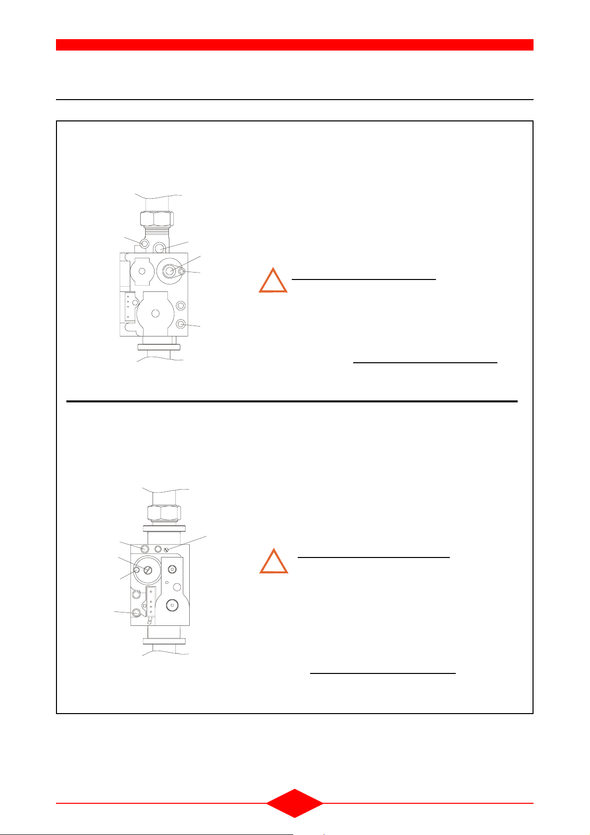
II - GAS CONVERSION
Check that the boiler is properly adapted to the gas
used, otherwise change the gas.
1 - GAS CONVERSION (THI 10-50 C ONLY)
This operation must be carried out by a
qualified person equipped with a cali-
!
brated combustion analyser.
Prior to any servicing cut the electrical and gas supplies.
The boiler is preset in the factory for natural gas H
Fig. 4
PL
K
Pi
2
V
Po
1
9
8
5
10
(G20) 20 mbar.
When changing the gas, the "gas setting" label that
is in the gas conversion set must be fixed on the inside of the boiler so as to indicate the new setting.
Check the gas circuit for leak tightness after each intervention on the boiler.
1) Gas unit
4
67
3
2) Gas pipe
3) Flange Burner/fan
4) Burner
5) Air/Gas servo-control
6) Brass air reducer
7) Fan
THI-36-0
8) Flat seal
9) Gas reducer
10) Gas reducer o-ring
1.1 - Conversion from Natural Gas to Propane
- Conversion to propane (G31) requires the gas
conversion set (ref : V07.31651)
- Refer to the installation instructions of the gas
conversion set
1.2 - Conversion from Propane to Natural gas
Air inlet of burner :
- Gently separate the fan (7) from the burner (4) at
the level of the flange (3),
- Take off the air reducer (6) into the air inlet sleeve
of the burner,
- Gently refit the fan (7) together with its joint to the
burner flange (3).
Gas valve outlet:
- Remove the nut securing the gas tube (2) to the
gas valve (1),
- Take off the propane gas reducer (9) and o-ring
(10) at the outlet of the gas valve (1),
- Fit the gas tube/gas valve assembly and check
that the flat joint (8) is fitted correctly,
- Check that between the gas tube (2) and gas valve (1) is gas-tight (burner on) by using a foaming
product,
- Check the CO2/CO rate (refer setting table
section 2.2 - page 12 - chapter II - GAS CONVERSION - SERVICING MANUAL).
- 9 -
GAS CONVERSION
1
2- GAS/CO2/CO/NOX FLOW CONTROL AND SERVICE PRESSURE CONTROL
Fig. 5 Pi = Network gas pressure
Natural gas H (G20) : 20 mbar,
GAS VALVE
SIEMENS/LANDIS
ref : VGU87A0236
Propane (G31) : 37 mbar.
P
= Outlet gas pressure to the burner.
o
PL = Air pressure control (fan/gas valve)
V = Adjust the slope of the characteristic of the air/gas ratio only
when the burner is at high rate. This setting is carried out in
the factory for natural gas type H (G20). This means that the
Po
V
K
PL
pressure Po can be changed to obtain the required gas flow
(section 2.2 - page 12 - chapter II - GAS CONVERSION SERVICING MANUAL).
Screw to increase the gas flow
!
K = Adjust the parallel shift of the characteristic of the air/gas ratio
only when the burner is at low rate. This screw is pre-set in
ZEM-54-0
Pi
the factory. Its setting must not be normally modified even for
changing gas. If however an adjustment is required, it may be
carried out with a low scale pressure gauge 0-10 mmCE, and
a CO2, CO analyser. Screw to increase the gas flow
.
P_OUT
P_IN
GAS VALVE
SIT
ref : 848 SIGMA
2
PL
P_IN =Network gas pressure
Natural gas H (G20) : 20 mbar,
Propane (G31) : 37 mbar.
P_OUT = Outlet gas pressure to the burner.
PL = Air pressure control (fan/gas valve)
1 = Adjust the slope of the characteristic of the air/gas ratio only
when the burner is at high rate. This setting is carried out in
the factory for natural gas type H (G20). This means that the
pressure "P_OUT" can be changed to obtain the required gas
flow . (section 2.2 - page 12 - chapter II - GAS CONVERSION - SERVICING MANUAL).
Screw to descrease the gas flow
!
2 = Adjust the parallel shift of the characteristic of the air/gas ratio
only when the burner is at low rate. This screw is pre-set in
the factory. Its setting must not be normally modified even for
changing gas. If however an adjustment is required, it may be
carried out with a low scale pressure gauge 0-10 mmCE, and
a CO2, CO analyser
To modify the setting, if it is required, take off the protection
screw, and screw to increase the gas flow
justments are realized, reset the protection screw.
. When the ad-
- 10 -

GAS CONVERSION
Fig. 6
23
THI-126-0
23
chimney flue:
B
23
- Combustion control is carried out after making a
hole on the combustion product outlet system ex-
ternal and directly at the boiler outlet (with the boiler unit assembled). This opening must be closed
again after checking.
• the burner switches to the minimum rate,
-Check the CO
/CO ratio (see setting table
2
section 2.2 - page 12 - chapter II - GAS CONVERSION - SERVICING MANUAL),
- If necessary:
• adjust screw K or 2 (fig. 5 - page 10 - SERVICING MANUAL) (tightening and untightening
increases and decreases gas flow).
Before starting the minimum rate setting (V or 1 and K or 2 screws), wait for
!
a stable CO
/CO analyser read-out.
2
Repeat switching from the minimum
THI-130-0
rate to the maximum rate several times
to ensure that the setting has been
done properly.
- to return to normal operation, press on the sweep
key (rep. 6) for 3 seconds then release it.
Note:
- Remember to reposition the d.h.w. potentiometer
(3) to its initial value to return to the required
d.h.w. setting.
C
- C33 balanced flue:
13
- Combustion control is carried out through the
opening (23) provided for this purpose after the
cap is removed. This opening must be closed
again after checking.
2.1 - Surveillance procedure
- To commission the burner:
• Activate the regulator shut-down function - ser-
vice key (6) (section 3.11 - page 19 chapter III - OPERATION - INSTALLATION
MANUAL) :
. the code flashes on the dis-
play screen (13),
- Gradually position the d.h.w. potentiometer (3) to
the maximum on the right:
• the burner switches to max. rate,
- Gradually move the V or 1 adjustment screw of
the gas unit (fig. 5 - page 10 - SERVICING MANUAL) to obtain a stable flame.
-Check the CO
/CO ratio (see setting table
2
section 2.2 - page 12 - chapter II - GAS CONVERSION - SERVICING MANUAL),
- Set the d.h.w. potentiometer (3) to the maximum
on the left:
- 11 -

GAS CONVERSION
2.2 - Setting table
Models THI 10-50 THI 10-35 SEP
Burner type X07.36237
Heat output 30/50 °C
60/80 °C
Heat input kW 10,0/50,0 10,0/35,0 10,0/50,0
∅ Gas reducer Nat. gas H
Propane
∅ Air reducer Nat. gas H
Propane
Gas flow (15 °C 1013 mbar)
Gas pressure P
Air pressure servo-system (PL) Pa 40/630
CO
Emission Nat. gas H
2
CO Emission Nat. gas H
/ P_OUT (Gas unit to burner)
o
Nat. gas H
Propane
Propane
Propane
kW
kW
mm
mm
mm
mm
3
m
/h
kg/h
mbar 0,25/2,4
%
%
ppm
ppm
10,7/52,6
9,7/48,7
Heating Heating D.H.W
-
6,40
-
31
1,06/5,29
0,78/3,88
8,0-8,5/9,0-9,5
10,0-10,5/10,5-11,0
0/20
0/40
1,06/3,70
10,7/36,0
9,7/33,1
-
-
-
-
1,06/5,29
-
8,0-8,5/9,0-9,5
-
0/20
-
-
- Combustion product evacuation outlet back pressure: 0 mmCE.
- P
/ P_OUT = Gas pressure at the gas valve re-
o
gulator outlet.
- PL = Servo-system air pressure (Fan/gas unit).
- The Po
/ P_OUT and PL values may be more or
less high according to whether back pressure is
greater or smaller.
- 12 -
III - MAINTENANCE
The annual inspection of the boiler and of the combustion product outlet is compulsory and validates
the warranty. It must be carried out by a qualified
person.
Spare parts must be ordered by using the references listed in chapter VI - PARTS LISTS - page 27 SERVICING MANUAL, and specifying the type and
serial number of each part.
Before any servicing, cut the power
supply. Close the gas inlet of the boiler
!
and the isolation valves if required.
If the boiler is removed, provide a port
at the end of the gas piping.
1 - SERVICING THE FAN AND THE BURNER
Fig. 7
23
9
Remove the front panel (item G) from
the boiler and disconnect the earth wire
!
(item O).
O
B
7
4
5
G
8
A
Check the state of the ventilator and the burner and
clean them if necessary (following their service instructions).
4
THI-97-0
6
10
1
7
- 13 -

MAINTENANCE
Disassembling the burner/fan unit:
- Disconnect the electrical connections of the burner/fan unit:
• remove the 2 terminals of the cables connect-
ing the ignition electrode (item. 3) to the ignition transformer (rep. A,
• removal the terminal of the cable connecting
the ionization electrode (item. 2) to the X2-05
terminal of the control panel,
• removal at the fan (item. 7):
. of the connector of the power cable from the
fan,
. of the connector of the PWM signal from the
fan,
- disconnect the air/gas control (item B) from the
gas valve
Disassembling the fan:
- Unscrew the four screws (1) fixing the fan (7) to
the burner’s air sleeve (6),
- Clean the fan (item. 7) using a domestic vacuum
cleaner by placing the suction device over the air
inlet and outlet successively.
Cleaning the burner:
- Unscrew the four screws fixing (5) the burner (4)
to the boiler shell (8),
- Disassemble the nut (9),
- Clean the burner (4) using a domestic vacuum
cleaner by placing the suction device over the air
inlet and the gas inlet successively,
- Check the ignition electrodes (3) and the ionisation electrodes (2).
Fig. 8
3
39
2.25
ZEM-31-0-5-25
2
40
20
≈
When reassembly the burner/fan unit:
- Replace the seal at the nut (item. 9) and check
the airtightness of the gas,
- when refitting the fan on the burner :
• check the correct positioning of the fan/burner
gasket (item. 10),
• check the airtightness of the gasket and repla-
ce it if necessary.
- check airtightness at the burner and boiler shell
levels,
2 - SERVICING THE HEAT EXCHANGER OF THE BOILER SHELL
- The heat exchanger must be cleaned once the
burner has been disassembled (section 1 page 13 - chapter III - MAINTENANCE - SERVICING MANUAL).
- Sprinkle the heat exchanger with water. The water is evacuated through the condensate evacuation siphon,
- when reassembling the burner onto the boiler
shell check the correct positioning of the gasket.
3 - CHECKING ACCESSORIES
- Check that the safety and control devices (3 bar
safety valve, air bleed, safety control box, etc.)
are operating properly.
- Clean the condensate drain siphon and then fill it
with water.
- Also check that neither the installation nor the
boiler present any water or fuel leaks (leaks may
produce a risk for safety and shorten the lifespan).
- When it is frequently necessary to add water to
maintain pressure in the installation, even though
no leaks have been discovered, perform an expansion vessel check (section 4 - page 15 chapter III - MAINTENANCE - SERVICING MANUAL).
- 14 -

4 - EXPANSION VESSEL PRE-INFLATION PRESSURE CHECK
MAINTENANCE
- Drop the pressure in the heating installation by
opening the drain cock or the safety valve (pressure gauge reading under 0.5 bar).
- Check the pressure in the expansion vessel and
Fig. 9
if necessary bring it back up to pressure, or replace it if the membrane is punctured (water present
in the inflating valve).
- To optimise the efficiency of the vessel:
• adjust its pre-inflation pressure in line with the
installation. It must correspond to the static height of the installation (H) expressed in bars
Water inlet
(height between the highest point of the installation and the expansion vessel, with 10 metres = 1 bar),
• adjust the filling pressure of the installation to a
value of over 0.2 bar above the pre-inflation
Inflating
valve
5 - COMBUSTION PRODUCT CONDUITS (FLUE)
- Check the combustion product evacuation conduit and the air inlet conduit at least once a year
(airtightness of the parts that may be disassembled - conduits not obstructed).
pressure of the vessel (after totally bleeding
the air from the installation).
H
Membrane
Max vessel
volume
Dilated water
volume
Pressure rises
as the air is
compressed
AM4-06-3
6 - DRAINING
- Cut the power supply,
- turn off the gas cock,
- turn off the heating flow/return valves (if they are
fitted),
- connect the drain valve (18) to the sewage system,
- open the drain valve.
Ensure that the air bleed (16) is open, as
soon as the pressure gauge indicates a
!
zero pressure to allow air to enter the
boiler shell.
Fig. 10
16
18
THI-98-0
- 15 -

7 - SENSOR RESISTANCES
0
0 0.5 1 1.5 2 2.5 3 3.5 4 4.5 5
0
0.5
1
1.5
2
2.5
3
3.5
4
4.5
5
Input pressure (bar)
100-74-0
Output voltage (Volt)
MAINTENANCE
The resistance of the sensors must be measured
after they have been disconnected from the control
panel.
Resistance values of the sensors
Heating outlet sensor
Temperature
0.00 °C 32624
10.00 °C 19897
15.00 °C 15711
20.00 °C 12493
25.00 °C 10000
30.00 °C 8056
40.00 °C 5324
50.00 °C 3599
60.00 °C 2483
70.00 °C 1748
Boiler return sensor
Flue gas sensor
Resistance values of the sensors
Heating outlet sensor
Temperature
Boiler return sensor
Flue gas sensor
80.00 °C 1252
90.00 °C 912
Resistance values of the sensors
Temperature Outside sensor
-20.00 °C 7578
-15.00 °C 5861
-10.00 °C 4574
-5.00 °C 3600
0.00 °C 2857
5.00 °C 2284
10.00 °C 1840
15.00 °C 1492
20.00 °C 1218
8 - PRESSURE SENSOR
The output voltage on the water pressure sensor is measured between the terminals GND (-) and OUT.
Fig. 11
OUT
GND (-)
IN (+)
100-75-
- 16 -

IV - OPERATING FAULTS
1 - OPERATING FAULTS LIST
Display A0 Description Solution
Outside sensor fault Check that the sensor is correctly fitted and
connected
Boiler sensor 1 fault Check that the sensor is correctly fitted and
connected
Flue gas detector fault Check that the sensor is correctly fitted and
connected
Flow sensor 2 fault Check that the sensor is correctly fitted and
connected
Return sensor 1 fault Check that the sensor is correctly fitted and
connected
Domestic hot water sensor 1 fault Check that the sensor is correctly fitted and
connected
Room device 1 faulty Check the boiler connections
Room device 1 error or radio clock error Check compatibility of the room device or
clock
Water pressure sensor fault Check the connections of the pressure
sensor
Short-circuit on LPB or no voltage Check the wiring
Two identical addresses on the LPB Check the addressing
Loss of data in the EEPROM Change the LMU
Component fault in the LMU Change the LMU
Two master clocks (only one normally),
programming problem
Maintenance alarm Check the maintenance code value, QAA 73
STB (boiler overheating safety) activated Check that shunt X3-01 is present and
Response of the safety thermostat Check whether the installation water flow is
Check parameter 96 of the QAA73 (only one
device can have the message “QAA73”)
setting 726 (section 2 -page 19 - chapter IV OPERATING FAULTS - SERVICING
MANUAL)
whether the installation water flow is sufficient
(circulating pump, isolation valve, etc.)
sufficient (circulating pump, isolation valve,
etc.)
Flue gas alarm displayed (problem of the
flue gas temperature being too high)
Water pressure too high Check and adjust the pressure level if
Water pressure too low Check and adjust the pressure level if
- 17 -
Check whether the boiler is not on thermal
overload or that the exchanger is not clogged
necessary with P < 4 bar
necessary with P > 0.4 bar

OPERATING FAULTS
Display A0 Description Solution
Flame failure while the boiler is operating Check and adjust the gas valve, check the
ionisation electrode and the connections,
possible live-neutral inversion of the
transformer supply
Poor air supply Check the ventilator and the air inlet
Maximum flue gas temperature exceeded Check whether the boiler is not on thermal
overload or that the exchanger is not clogged
Safety device activated Check that shunt X10-03 is present and that
the wires are properly connected
No flame formed after the safety time
period
Segment number or unauthorised
addressing on LPB or LMU
Incompatibility between the LMU and LPB Check the addressing consistency
New LMU configuration Check the b0 internal code
LMU setting error Check the b0 internal code
The boiler is blocked Press Reset to clear the message
Violation of the plausibility criteria (STB
related criteria)
The minimum speed threshold of the fan
is not reached
The maximum speed threshold of the fan
is exceeded
Check that the gas reaches the boiler (Pi),
check the condition of the gas valve, if there
is a major adjustment fault on the gas valve,
check the condition of the transformer,
cables, ignition electrode, ionisation current
value
Check the addressing consistency
Check the value of the criteria related to the
boiler overheating security
Check the wiring of the fan and LMU, ensure
that the fan is turning correctly
Check the mains supply and the fan cable
connections
The service function is active -
The regulator shut-down function is active -
The boiler is in setting mode This appears after one or more settings are
Modem function is active -
"Controlled screed drying" function is
active
Note :
- The last 5 working faults are accessible through
the QAA 73, from LMU version 3.00, lines 728 /
loaded either by the QAA73 or by the PC
TOOL. This means that a reset is necessary
to validate the new setting(s) and for the
boiler to return to normal operating.
-
729 / 730 / 731 / 732. The last saved fault code is
displayed at line 728.
- 18 -

2 - MAINTENANCE
Maintenance alarms can be automatically triggered,
indicating that maintenance jobs are due. The following reasons for maintenance alarms can be delivered:
- Interval of burner hours run since last regular service visit exceeded.
- Interval of the number of startups since last regular service visit exceeded.
- Number of months since last regular service visit
exceeded.
The alarm displayed is always the maintenance
alarm that occurred first.
There is no storage for the maintenance alarms since all pending alarms can be checked at any time
via the counter readings or the relevant parameters.
2.1 - Maintenance alarm
If a maintenance alarm occurs, an error code "105
maintenance" appears on the dipslay of the boiler
and / or room unit.
This code does not give precise information on
maintenance but is only a general maintenance note.
OPERATING FAULTS
2.3 - Coding of maintenance alarms
Internal
Maintenance
alarm
Maintenance
code
– 0 –
105 1 560
105 2 561
105 3 562
error
code
b0
Meaning
No maintenance
alarm
Burner hours run
Startups
Months-service
2.4 - General activation of maintenance alarms
Parameter "WartungsEinstellungen" (QAA 73 setting : 630) permits or suppresses the generation of
maintenance alarms.
The subdivision of parameter "WartungsEinstellungen" by bit is shown in the following table :
These maintenance alarms are a priority lower than
that of the error codes to ensure the error codes prevail.
The maintenance alarm is sent until the enduser has
acknowledged the message or the heating engineer
has rectified the fault.
2.2 - Maintenance code
The maintenance alarm does not provide detailed
information about the reason for the fault. Details
can be displayed using parameter "WartungsCode"
(QAA 73 setting : 726).
Le maintenance code can also be viewed on the display of the boiler (b0).
Bit0
Bit1
1 = general activation of maintenance alarms
1 = single reset of hours run maintenance alarm
Bit2 1 = single reset of startup maintenance alarm
Bit3
alarm
single reset of months- service maintenance
1 =
Bit6 1 = total reset for all maintenance alarms
- 19 -

OPERATING FAULTS
2.5 - Activation of the individual maintenance alarm
Every cause can be individually activated or deactivated by entering the associated limits.
- Burner hours run :
Burner hours run maintenance is activated by
setting parameter "BetrStdWartGrenz" (QAA 73
setting : 625) to a value other than "0".
This value represents the target number of hours
run. When this limit is reached, a maintenance
alarm will be delivered (interval since last service
visit).
- Number of startups:
Startup maintenance is activated by setting parameter "InbetrSetzWartGrenze" (QAA 73 setting :
626) to a value other than "0".
This value represents the target number of star-
tups. When this limit is reached, a maintenance
alarm will be delivered (interval since last service
visit).
- Months (service):
Service maintenance is activated by setting parameter "MonatWartGrenze" (QAA 73 setting :
627) to a value other than "0".
This value represents the target number of
months. When this limit is reached, a maintenance alarm will be delivered (interval since last service unit).
Note :
- The month counter is only active when the device
is connected to power.
2.6 - Acknowledgement of maintenance alarms
The acknowledgement sets the internal error code
"b0" and the fault statut message to "0", but the
maintenance code still gives the precise reason for
the maintenance alarm.
2.6.1 - Acknowledgement via QAA 73
For the parameter "WartungsQuittierung" (QAA 73
setting : 629) (defaut value: 0), to acknowledge the
maintenance alarm the heating engineer (or the enduser) enters the value of "1".
If no repetition is required, all maintenance alarms
after this acknowledgement will be locked, even if
other reasons for maintenance occur. In that case,
parameter "WartungsQuittierung" remains constantly at 1.
2.6.2 - Activation of the repetition after acknowledgement
If required, a timer (duration of repetition) can be
started, that is, the maintenance alarm will reappear
on the display after a certain period of time. An acknowledgement can also be made then. This period
of time starts after each acknowledgement.
The repetition can be set via parameter «WartungsRepetitionsDauer» (QAA 73 setting 633).
Contents of parameter «WartungsRepetitionsDauer» is the desired period of time (in days) until
the maintenance alarm appears again.
If a value other than «0» is entered there, a repetition is made within the entered duration of the repetition time.
During this period of time, no more
maintenance alarms will appear, even if
!
other reasons for maintenance occur.
2.7 - Resetting the maintenance alarms
Resetting can take place at any time, and after acknowledgement or during the repetition sequence.
A reset can be made in 1 of 2 ways:
- Total reset :
Here, all maintenance alarms can be reset at the
same time. If, in parameter «WartungsEinstellungen» (QAA 73 setting 630), «1» is entered, all
maintenance counters will be set to «0» when the
parameter is saved.
The maintenance counters of the hours run, startups and months maintenance alarms will be
newly started.
- Individual resert of a certain maintenance
alarm :
Individual maintenance alarms can also be reset.
In that case, parameter «WartungsEinstellungen» (QAA 73 setting : 630) will again be addressed bit by bit.
There is a bit available for each maintenance
alarm via which this maintenance alarm can be
reset (section 2.4 - page 19 - chapter IV - OPERATING FAULTS - SERVICING MANUAL). It is
thus possible to also reset other reasons for
maintenance although they have not yet occurred.
When resetting the maintenance alarm, the maintenance code and the internal error code (b0) will
automatically also be reset.
Note : Only the QAA 73 can the maintenance alarms
be activated, the reasons for the maintenance alarms be checked and a reset via parameter be made.
- 20 -
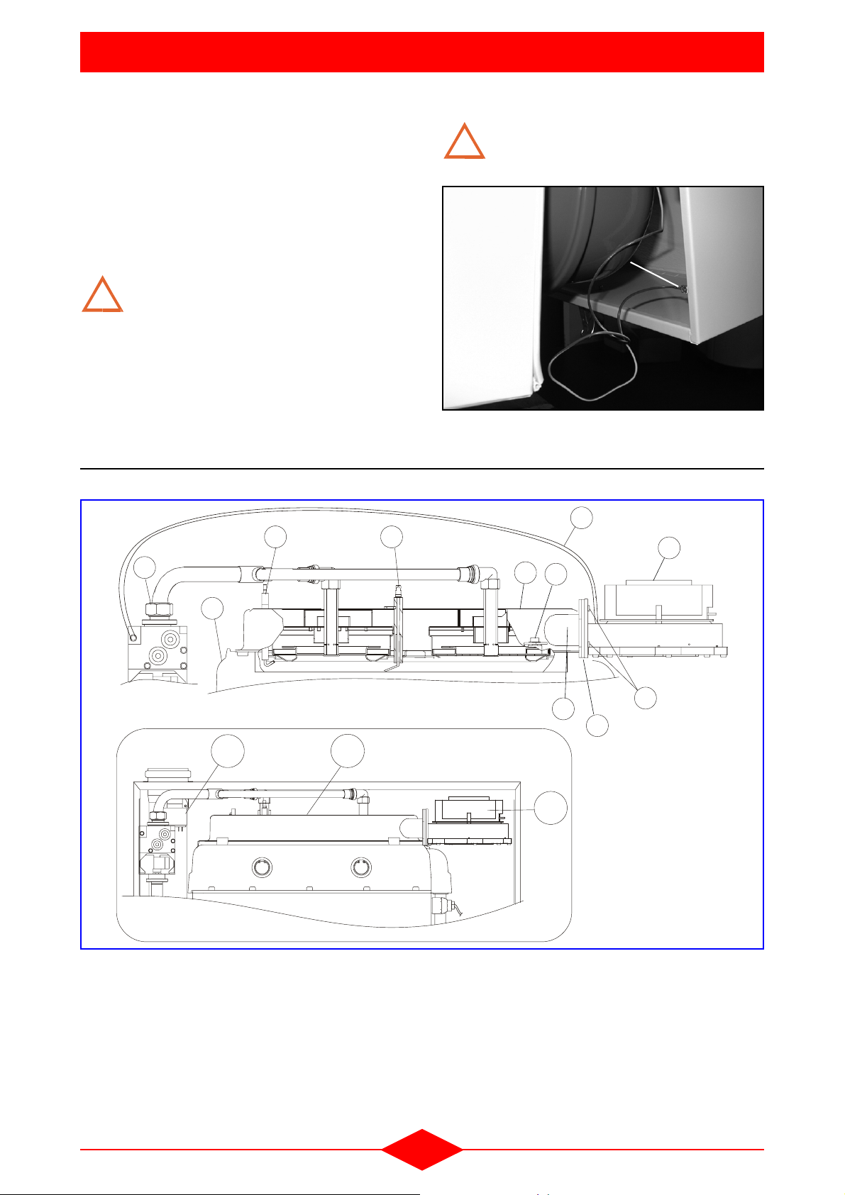
V - OPTIONS
1 - SET-UP TAKING ROOM TEMPERATURE INTO ACCOUNT (REG 73)
The REG 73 is a multifunctional digital room sensor
for one or two heating circuits and for the control of
domestic hot water.
Refer to the kit installation instructions.
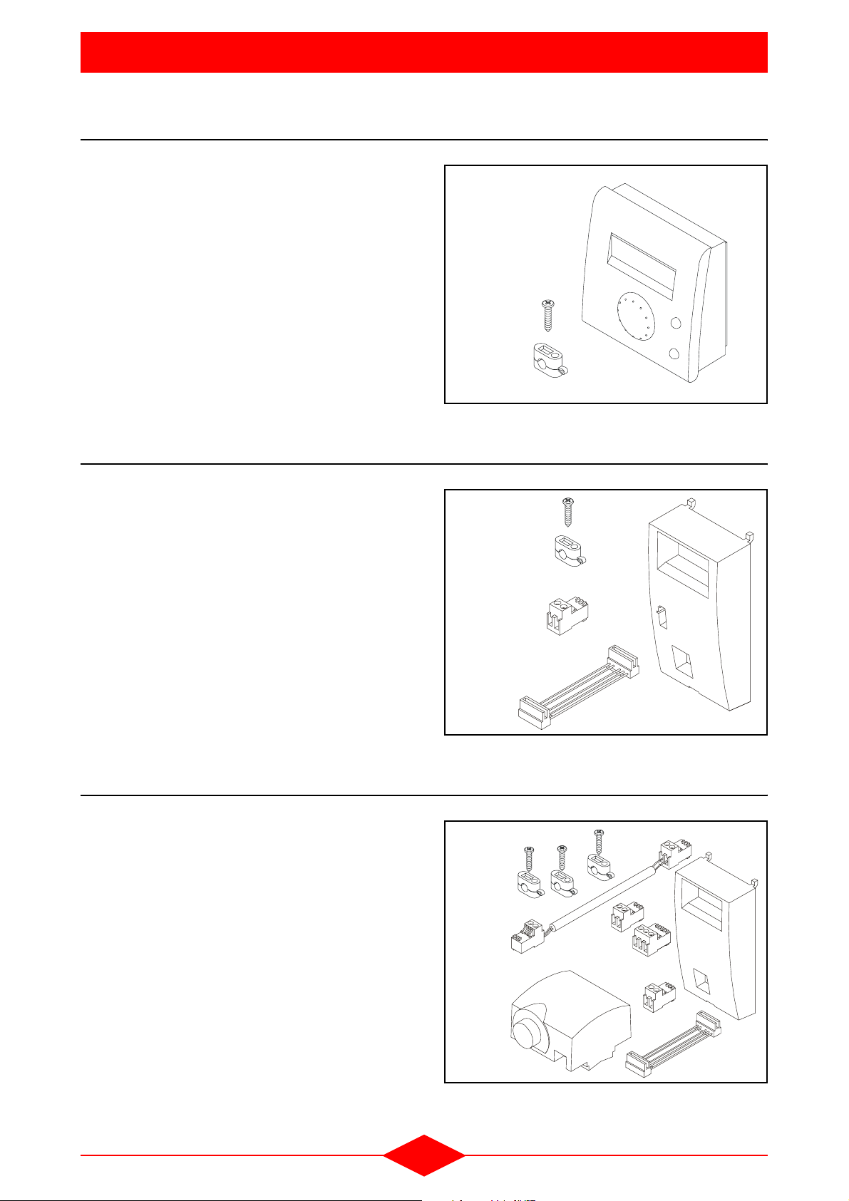
2 - CLIP-IN LPB KIT (REG 130)
The LPB communication clip-in kit is used to
connect the LMU control unit to different units or
accessories of the type:
- RVA 46: zone regulator
- RVA 47: cascade regulator
- + others (distance management etc.)
Fig. 12
PDG-REG 73
Fig. 13
Refer to kit installation instructions.
3 - SECONDARY CIRCUIT CLIP-IN KIT
The secondary circuit clip-in kit is used when a
second heating circuit is connected to the boiler. It
allows the communication between the boiler’s LMU
control unit and the various accessories of the
secondary circuit.
Refer to kit installation instructions.
THI-28-0
Fig. 14
- 21 -
0
1
3
-
I
H
T

4 - DOUBLE CIRCUIT KIT (REG 125) - (THI 10-35 SEP)
0
OPTIONS
The double circuit kit is used whenever a second
heating circuit is connected to the boiler:
Fig. 15
- The 2nd circuit clip-in ensures communication
between the boiler's LMU management unit; the
2nd circuit pump control and also the mixing valve motor (accessories supplied with the kit).
Refer to kit installation instructions.
5 - DOUBLE CIRCUIT KIT (REG 146) - (THI 10-50 C)
The double circuit kit is used whenever a second
heating circuit is connected to the boiler:
- The 2nd circuit clip-in ensures communication
between the boiler's LMU management unit; the
2nd circuit pump control and also the mixer valve
motor (accessories supplied with the kit).
- The clip-in relay allowing a 1st circuit pump (Q8CC1) to work in parallel and to regulate the outlet
temperature of the installation.
Fig. 16
0
8
1
-
I
H
T
9
1
-
I
H
T
Refer to kit installation instructions.
6 - PROGRAMMABLE RELAY CLIP-IN KIT (REG 127)
The programmable relay clip-in kit (sensor inlet)
enables:
- a 2nd heating pump to be controlled in parallel
with the boiler pump in the case of operation
using a header.
- with the flow sensor positioned at the outlet of the
header, the heating outlet can be controlled after
the header.
- an external safety gas solenoid to be connected,
- an alarm to be connected.
Refer to kit installation instructions.
Fig. 17
0
1
3
I
H
T
- 22 -

7 - PROGRAMMABLE RELAY CLIP-IN KIT (WITHOUT SENSOR) (REG 134)
OPTIONS
The programmable relay clip-in kit (without sensor)
enables, for example:
- a domestic hot water circulation pump to be controlled,
- an outside gas safety solenoid valve to be connected.
Refer to the assembly instructions for the kit.
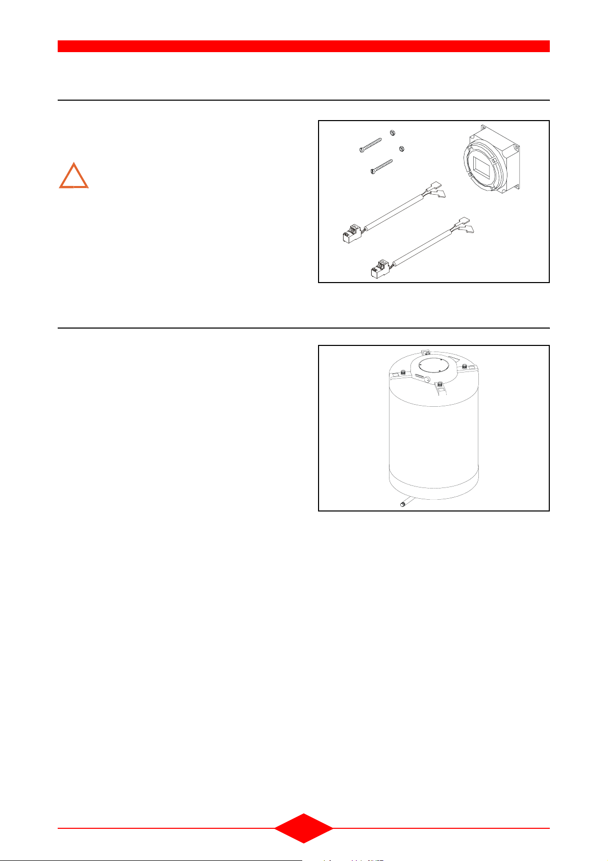
8 - CONTROL UNIT ZHTI 46 (REG 129)
The control unit ZHTi 46 enables an additional heating circuit to be controlled. (Required from 3 heating
circuits - refer to technical specifications of the ZHTi
46).
Fig. 18
Fig. 19
0
9
0
1
-
I
H
T
9 - CONTROL UNIT ZHTI 47 (REG 128)
The control unit ZHTi 47 manages 2 cascading boilers.
Note:
- For multiple boiler management, use clip-in kits
LBP (130).
Refer to ZHTi 47 technical specifications.
REG 121
Fig. 20
REG 128
- 23 -

10- SOLAR HEATING CONTROL KIT (REG 152)
OPTIONS
The solar heating control kit is intended for type C
THI boilers that have a solar tank. It is used to control the production of domestic hot water by solar panels.
11 - DHW SENSOR KIT
The DHW sensor kit allows the connection of the domestic hot water sensor to the hot water heater at
the boiler control unit.
Fig. 21
REG-SOL1-0
Fig. 22
Refer to kit installation instructions.
12- SELECTOR VALVE KIT FOR CONNECTING THI..C/BS
The selector valve kit allows the connection of a
central heating only type boiler to a domestic hot
water heater.
Refer to kit installation instructions.
Fig. 23
THI-67-0
THI-37-0
- 24 -
13- TIMER KIT
S
OPTIONS
The timer kit is fitted to the boiler’s control panel and
controls an installation only possessing one heating
Fig. 24
circuit.
Fitting a clip-in to the boiler’s LMU management unit will not work with this ti-
!
mer.
Refer to kit installation instructions.
14- BS TYPE DOMESTIC HOT WATER PRODUCTION SYSTEM
BS domestic hot water production systems can produce hot water when the installation contains a boiler that only operates for heating.
The capacity of the BS systems varies with the model chosen.
- BS 100: 100 litres / BS 200: 200 litres
- BS 150: 150 litres / BS 300: 300 litres
Fig. 25
HOR-01-0
Note:
- The selector valve kit is necessary for connecting
BS systems to ZEM..C boilers.
B
- 25 -
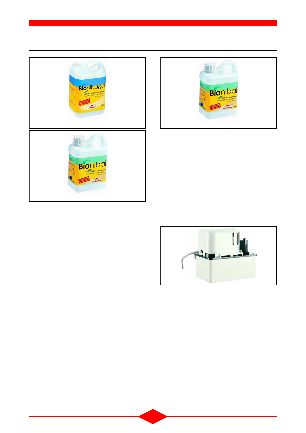
15- BIONIBAL/BIONIBAGEL
OPTIONS
Fig. 26
Fig. 27
BIONIBAGEL 10 litres
BIONIBAL 1 litre
Fig. 28
BIONIBAL 30 litres
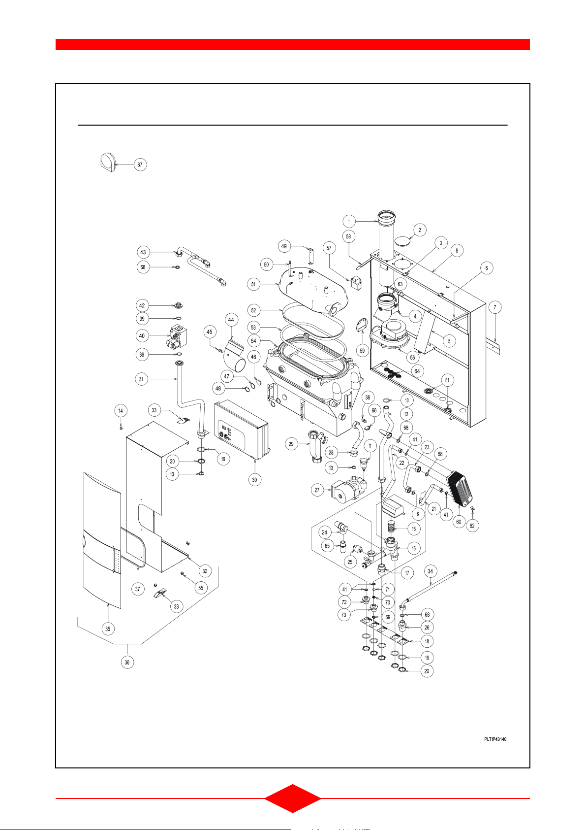
16- CONDENSATE LIFT PUMP
The condensate lift pump is used to raise the condensate extraction level for a direct outlet to the exterior. It is used for boilers installed in a basement.
Fig. 29
- 26 -

VI - PARTS LISTS
THI 10-50 C
- 27 -

PARTS LISTS
Rep.
1 N40.16810 REDUCED FLUE OUTLET PIPE F75/M80 L360
2 A00.23624 PE CAP N152 BPF 3-1/2
3 Y00.14139 FASTENING HOOK
4 Y00.10807 FIXING SYSTEM FOR FLUE PIPE
5 Y00.13849 BACK STOP PLATE FOR MZ (3355X80,4X1,5)
6 Y00.18233 RIGHT HAND CONSOLE (269,4X25X1,5)
7 V07.31963 WALL FASTENING ; 10-50 MODEL
8 Y90.33470 CHASSIS ; EQUIPPED THI 10-50
9 A00.24109 ORANGE CAP D. 34,7 EZ-16
10 E00.01005 O’ RING DIA DIA 29,32 X 3,6
11 L90.24635 AUTOMATIC AIR VALVE WATTS WITH ISOLATED VALVE
12 U00.19465 HEATING FLOW PIPE GREY THRC
13 E20.03889 SEALING AFM34D 30X21X3
14 W07.32303 OUTSIDE SENSOR .QAC34/101 THRI
15 H30.24159 MESSING CAP 28X52 + 2 O’RING
16 U90.28983 HEATING RETURN UNIT
17 I20.21441 MESSING SEALED CONNECTION "OLIVE" 22/1
18 V00.23999 STOP PLATE FOR HEATING AND DHW
19 V00.21491 PROTECTING RING 1
20 I20.21452 MESSING LOCK NUT 1
21 K50.24473 DRAIN COCK / RETURN UNIT
22 E00.24496 SEALING / O’RING INT. D. 39,45
23 L40.24495 STAINLESS STEEL FILTER / HEATING RETURN
24 L50.35152 PRESSURE SENSOR HUBA TYPE 505.91540
24 V90.35156 REPLACEMENT SET OF IMIT SENSOR BY HUBA SENSOR
25 L90.24178 SAFETY VALVE
26 L20.31471 SENSOR T7335D1024B
27 L30.33738 CIRCULATING PUMP GRUNDFOS UPS15-70/130 AO S3
28 U00.19252 SUMP INLET THRC/S GREY
29 A20.23655 SIPHONIC TRAP WITH PIPE 650 MM
30 W07.31562 CONTROL BOX PROGRAMMED THRI/THI 10-50C (DT)
31 U07.31500 GAS INLET; EQUIPPED; 1/10 - 5/25 MODEL
32 Y90.35965 WHITE COVER THRI S/10-50C
33 T25.31875 FIXING PART; UPPER COVER
34 E20.03890 SEALING AFM34 D 24X17X3
35 H20.32834 FRONTPANEL GREY
36 Y07.32843 COVER + FRONTPANEL
37 V07.32114 RING FOR BOILER COVER L685
38 L20.31470 SENSOR TASSERON NTC SENSOR M5 TSA-TYPE
39 L10.10607 HONEYWELL O’RING 22 X 2,5
40 V90.33616 WIRED SIT GAS VALVE SET
40 V90.37322 GAS VALVE SIEMENS VGU 87
41 I20.31604 GAS REDUCER
42 L10.33774 FLANGE G 3/4" FOR SIT VALVE
43 U07.31563 GAS INLET; COMPLETE BURNER ; 10-50C MODEL
44 U07.31498 90° ELBOW ; D.80 DRILLED
45 L20.31496 SENSOR TASSERON NTC SENSOR D10X20 10K
46 T20.00582 SIGHTGLASS PYREX D.30X5
47 B59.00692 STAINLESS STEEL WASHER 30,4X25,5X0,3
48 T40.01051 INSIDE CIRCLIPS D.30 YELLOW BICHROMATE
49 L00.16673 IGNITION ELECTRODE SHORT 74,5 AV CABLE
50 L00.12950 IONISATION PROBE (SHORT 20)
51 X00.24278 BURNER SET NG/LPG FOR THR 10-50 C
52 X00.32003 BURNER RING; REMOVABLE
53 F00.26573 GLASS BRAID RING D. 12 LG. 1070
Reference
Description
- 28 -

PARTS LISTS
Rep.
54 V07.33783 STAINLESS STEEL BOILER SHELL THRI/THI/THISION10-50
55 A00.03141 COLORLESS PLASTIC CAP
56 C50.31464 FAN MVL-EBM RG 128/1300-3612
57 C90.31466 IGNITION TRANSFORMER ANSTOSS ZAG 2XV 01/10
58 Y00.18234 LEFT HAND CONSOLE (269,4X25X1,5)
59 E20.35446 RING FOR THE FAN
60 I20.22440 MESSING AIR REDUCER D. 310 LP 16 (POUR REGLAGE PROPANE G 31)
61 E20.23654 EXTENSIBLE SEALING D. 18 / RED SILICONE
62 E00.03424 NITRILE O’RING D. 8 X 2 80 SHORE
63 U00.20366 ELBOW D. 80 45°
64 C91.03071 WIRE CARRIER
65 I20.13579 BRASS NIPPLE MAL3/4-MAL3/4(LONG)
66 A00.19059 PLASTIC STOPPER MAL 9 WHITE
* A00.28827 PLASTIC CAP MALE 1/4
* C09.31469 CABLE WITH RECTIFIER VDU GAS VALVE
* C09.33608 CABLE 0.960.401+CONNECT. GAS VALVE SIT 848 SIGMA
* E00.10822 EPDM LIP SEAL D. 80 75 SHORE
* E10.12503 EPDM STICKING SEAL PIPE 6/9 LENGTH 18
* E20.24399 GASKET DN 80; BLACK FOR PART NUMBER U00.12053 AND U00.20366
* I30.31973 STOP TECHNYL D.20X19
* U00.03505 FIXING BRACKET FOR BURNER MZ/THR
* U00.08190 VERSILIC PIPE 6X10 LENGTH 800MM
* U00.18996 FLEXIBLE PIPE 4X8 LG 800 MM GAS UNIT
* V00.24191 MOUNTING KEY; HONEYWELL
* V07.31651 GAS CONVERSION SET GN/GP
* X00.05193 FIXING BRACKET FOR IONISATION PROBE
* X90.30472 IGNITION ANGLE WITH SCREW
Reference
Description
- 29 -
THI 10-35 SEP
PARTS LISTS
- 30 -

PARTS LISTS
Rep.
1 N40.10637 PP. PIPE D.80 LENGTH 445
2 A00.23624 PE CAP N152 BPF 3-1/2
3 Y00.14139 FASTENING HOOK
4 Y00.10807 FIXING SYSTEM FOR FLUE PIPE
5 Y00.13849 BACK STOP PLATE FOR MZ (3355X80,4X1,5)
6 Y00.18233 RIGHT HAND CONSOLE (269,4X25X1,5)
7 V07.31963 WALL FASTENING ; 10-50 MODEL
8 Y90.33470 CHASSIS ; EQUIPPED THI 10-50
9 W07.31704 MOTOR; SELECTIVE VALVE WITH CABLE
10 E00.01005 O’ RING DIA DIA 29,32 X 3,6
11 L90.24635 AUTOMATIC AIR VALVE WATTS WITH ISOLATED VALVE
12 U07.34049 HEATING FLOW; GREY; THRI SEP
13 E20.03889 SEALING AFM34D 30X21X3
14 A00.19059 PLASTIC STOPPER MAL 9 WHITE
15 V90.33015 SELECTOR VALVE KIT
16 U90.28983 HEATING RETURN UNIT
17 I20.21441 MESSING SEALED CONNECTION "OLIVE" 22/1
18 V00.23999 STOP PLATE FOR HEATING AND DHW
19 V00.21491 PROTECTING RING 1
20 I20.21452 MESSING LOCK NUT 1
21 O00.32983 RIGHT FLEXIBLE PIPE NU 1/2 LG 350
22 O00.32984 RIGHT FLEXIBLE PIPE NU 1/2 LG 550
23 U07.32871 PRIMARY OUTLET PIPE
24 L50.35152 PRESSURE SENSOR HUBA TYPE 505.91540
24 V90.35156 REPLACEMENT SET OF IMIT SENSOR BY HUBA SENSOR
25 L90.24178 SAFETY VALVE
26 I20.33459 CONNECTION 1’’ -3/4’’
27 L30.33738 CIRCULATING PUMP GRUNDFOS UPS15-70/130 AO S3
28 U00.19252 SUMP INLET THRC/S GREY
29 A20.23655 SIPHONIC TRAP WITH PIPE 650 MM
30 W07.36930 CONTROL BOX ; WIRED ; PROGRAMMED
31 U07.31500 GAS INLET; EQUIPPED; 1/10 - 5/25 MODEL
32 Y90.35965 WHITE COVER THRI S/10-50C
33 T25.31875 FIXING PART; UPPER COVER
34 O00.20679 STAINLESS STEEL FLEXIBLE PIPE MALE 1/4 WITH ELBOW
35 H20.32834 FRONTPANEL GREY
36 Y07.32843 COVER + FRONTPANEL
37 V07.32114 RING FOR BOILER COVER L685
38 L20.31470 SENSOR TASSERON NTC SENSOR M5 TSA-TYPE
39 L10.10607 HONEYWELL O’RING 22 X 2,5
40 V90.33616 WIRED SIT GAS VALVE SET
41 E20.06892 SEAL AFM34 D. 18,6 X 12 2 MM THICKNESS
42 L10.33774 FLANGE G 3/4" FOR SIT VALVE
43 U07.31563 GAS INLET; COMPLETE BURNER ; 10-50C MODEL
44 U07.31498 90° ELBOW ; D.80 DRILLED
45 L20.31496 SENSOR TASSERON NTC SENSOR D10X20 10K
46 T20.00582 SIGHTGLASS PYREX D.30X5
47 B59.00692 STAINLESS STEEL WASHER 30,4X25,5X0,3
48 T40.01051 INSIDE CIRCLIPS D.30 YELLOW BICHROMATE
49 L00.16673 IGNITION ELECTRODE SHORT 74,5 AV CABLE
50 L00.12950 IONISATION PROBE (SHORT 20)
51 X00.24278 BURNER SET NG/LPG FOR THR 10-50 C
52 X00.32003 BURNER RING; REMOVABLE
53 F00.26573 GLASS BRAID RING D. 12 LG. 1070
54 V07.33783 STAINLESS STEEL BOILER SHELL THRI/THI/THISION10-50
Reference
Designation
- 31 -

PARTS LISTS
Rep.
55 A00.03141 COLORLESS PLASTIC CAP
56 C50.31464 FAN MVL-EBM RG 128/1300-3612
57 C90.31466 IGNITION TRANSFORMER ANSTOSS ZAG 2XV 01/10
58 Y00.18234 LEFT HAND CONSOLE (269,4X25X1,5)
59 E20.35446 RING FOR THE FAN
60 I20.22440 MESSING AIR REDUCER D. 310 LP 16 (POUR REGLAGE PROPANE G 31)
60 V07.35762 PLATE HEAT EXCHANGER 35KW
61 E20.23654 EXTENSIBLE SEALING D. 18 / RED SILICONE
62 L20.32178 SURFACE TEMP. SENSOR T7335D1073B
63 U00.20366 ELBOW D. 80 45°
64 C91.03071 WIRE CARRIER
65 I20.13579 BRASS NIPPLE MAL3/4-MAL3/4(LONG)
66 L20.31471 SENSOR T7335D1024B
67 W07.32303 OUTSIDE SENSOR .QAC34/101 THRI
68 E20.03890 SEALING AFM34 D 24X17X3
69 L40.32888 DOMESTICCOLDWATERFILTERSTAINLESSSTEEL D. 18,5 EXT
70 L50.35756 FLOW LIMITER 16 L / MN
71 T40.32887 COPPER SEALING D.16 INT
72 K20.23797 3/4"-1/2 " CONNECTION ; BRASS
73 K20.32885 CONNECTION ; BRASS 3/4-1/2
74 I20.33459 CONNECTION 1’’ -3/4’’
* A00.28827 PLASTIC CAP MALE 1/4
* C09.33608 CABLE 0.960.401+CONNECT. GAS VALVE SIT 848 SIGMA
* E00.10822 EPDM LIP SEAL D. 80 75 SHORE
* E10.12503 EPDM STICKING SEAL PIPE 6/9 LENGTH 18
* E20.03901 SEALING QUALITY AFM34 D.11X4X3
* E20.24399 GASKET DN 80; BLACK POUR LES RÉFÉRENCES (U00.12053) ET (U00.20366)
* I30.31973 STOP TECHNYL D.20X19
* U00.03505 FIXING BRACKET FOR BURNER MZ/THR
* U00.08190 VERSILIC PIPE 6X10 LENGTH 800MM
* U00.18996 FLEXIBLE PIPE 4X8 LG 800 MM GAS UNIT
* V00.24191 MOUNTING KEY; HONEYWELL
* X00.05193 FIXING BRACKET FOR IONISATION PROBE
* X90.30472 IGNITION ANGLE WITH SCREW
Reference
Designation
- 32 -

CONTROL BOX
PARTS LISTS
- 33 -

PARTS LISTS
Rep.
1 H20.31449 CONTROL BUTTON
2 Y07.31525 CONTROL PANEL + STICKER
3 W07.31892 INTERFACE; EQUIPPED; AGU2.303A136
4 L20.31476 COMMUNICATION MODULE CLIP-IN LPB (VOIR OPTION W07.30832)
4 L20.31477 MODULE CIRCUIT 2 CLIP-IN (VOIR OPTION W07.30833)
4 L20.31499 SUB-MODULE RELAIS CLIP-IN AGU2.511A109 (VOIR OPTION W07.30515)
5 L20.36214 ELECTRONIC CONTROL UNIT LMU64.010D136 V3.03
6 A90.27098 CABLE GRIP D=6,5 MM BLACK
6 C91.38454 CABLE FASTENING TWIST LOCK
7 Y07.31507 ELECTR. BOX
8 C19.32006 SCREW EARTH CONNECTION
9 C20.12490 TIGHT CAP FOR SWITCH
10 C20.12487 BIPOLAR SWITCH; BLACK/LIGHTNING/GREEN
11 L25.17432 TIMER GRASSLIN 230 V FM - DIGI20
* C09.31469 CABLE WITH RECTIFIER VDU GAS VALVE
* C09.33608 CABLE 0.960.401+CONNECT. GAS VALVE SIT 848 SIGMA
* C09.37989 IONISATION CABLE Ø 2,5 LG 1020 MM
* C09.37989 IONISATION CABLE Ø 2,5 LG 1020 MM
* C90.31497 COVER KEY-TOP 4X4 THISION
* W07.31478 WIRING OF THE CONTROL BOX
* W07.31479 WIRING OF THE CONTROL BOX; 10-50 MODEL
* W07.31492 CONNECTING CABLE LG LMU64/AGU2
* W07.31508 ELECTR. CONTROL BOX + WIRING 2-13 THISION
* W07.31542 ELECTRICAL TERMINAL BOX
* W07.31558 ELECTR. CONTROL PANEL + WIRING 0,9-9 THISION
* W07.31562 CONTROL BOX PROGRAMMED THRI/THI 10-50C (DT)
* W07.32380 CONTROL BOX ; WIRED ; PROGRAMMED THI 5-25 S DT
* W07.32381 CONTROL BOX ; WIRED ; PROGRAMMED THI 2-13 M 75 DT
* W07.32382 CONTROL BOX; WIRED; PROGRAMMED THI 5-25 M75 DT
* W07.32899 CONTROL BOX ; WIRED ; PROGRAMMED THRI5-25SEP(DT)
* W07.32995 WIRING - TIMER THRI
* W07.34114 WIRED PROGRAMMED BOX THI 5-25/28 SEP GB/DK
* W07.34211 CONTROL BOX, PROGRAMMED, WIRED
* W07.34228 WIRED, PROGRAMM. CONTROL BOX THRI 5-25 M75H DC
* W07.34974 PROGRAMMED ; CONTROL BOX WIRING
* W07.35261 CONTROL BOX ; PROGRAMMED WIRING THI 2-17
* W07.35314 PROGRAMMED CONTROL BOX ; WIRING 2-17 B120
* W07.35319 PROGRAMMED CONTROL BOX ; WIRING 2-17 B120 DC
* W07.36535 WIRED & PROGRAMMED CONTROL BOX THI 5-25 B120 GB
* W07.36536 WIRED & PROGRAMMED CONTROL BOX THI 5-25 B120 DC
* W07.36930 CONTROL BOX ; WIRED ; PROGRAMMED
* W07.37986 SUPPLY CABLE 230V THRI
* W07.37991 CABLE TRANSFORMER+MASS THRI BURNER
* W07.37992 SWITCH CABLE THRI
* W07.37995 FAN CABLE THRI
* W07.37996 FAN CABLE THRI
* W07.37998 MASS CABLE THRI COVER
* W07.38000 SENSORS CONNECTION THRI
* W07.38001 CABLE PWM FOR THRI FAN
* W07.38002 FAN PWM CABLE THRI 10-50C
* W07.38004 SENSORS CONNECTION THRI 10-50 C
* W07.38379 FAN CABLE THRI/THISION/THI 10-50
* W09.37943 WIRING DHW SENSOR ZEM B120/SEP/M50
Reference
Designation
- 34 -
 Loading...