

Page 1
SERVICE MANUAL
PMX-80
Stereo Preamp Mixer
CONTENT’S:
Connections & Operations:.......................................................Page 2-4
Specifications:..............................................................................Page 5
Parts Lists:.................................................................................Page 6-8
PCBs:..........................................................................................Page 7-9
Schematics:.................................................................................Page 10
Gemini Sound Products Corp.
120 Clover Place P.O. Box 6928
Edison, NJ 08818-6928
732-738-9003 (Phone) • 732-738-9006 (Fax)
Page 1
Page 2
9
7 6
1
1
2
2
3
3
4
4
5
5
8 10
Page 2
Page 3
19
11
12 20
13
14
21
22
15
23
24
29
30
31
32
33
17
16
34
25
26
35
27
18
36
28
Page 3
Page 4

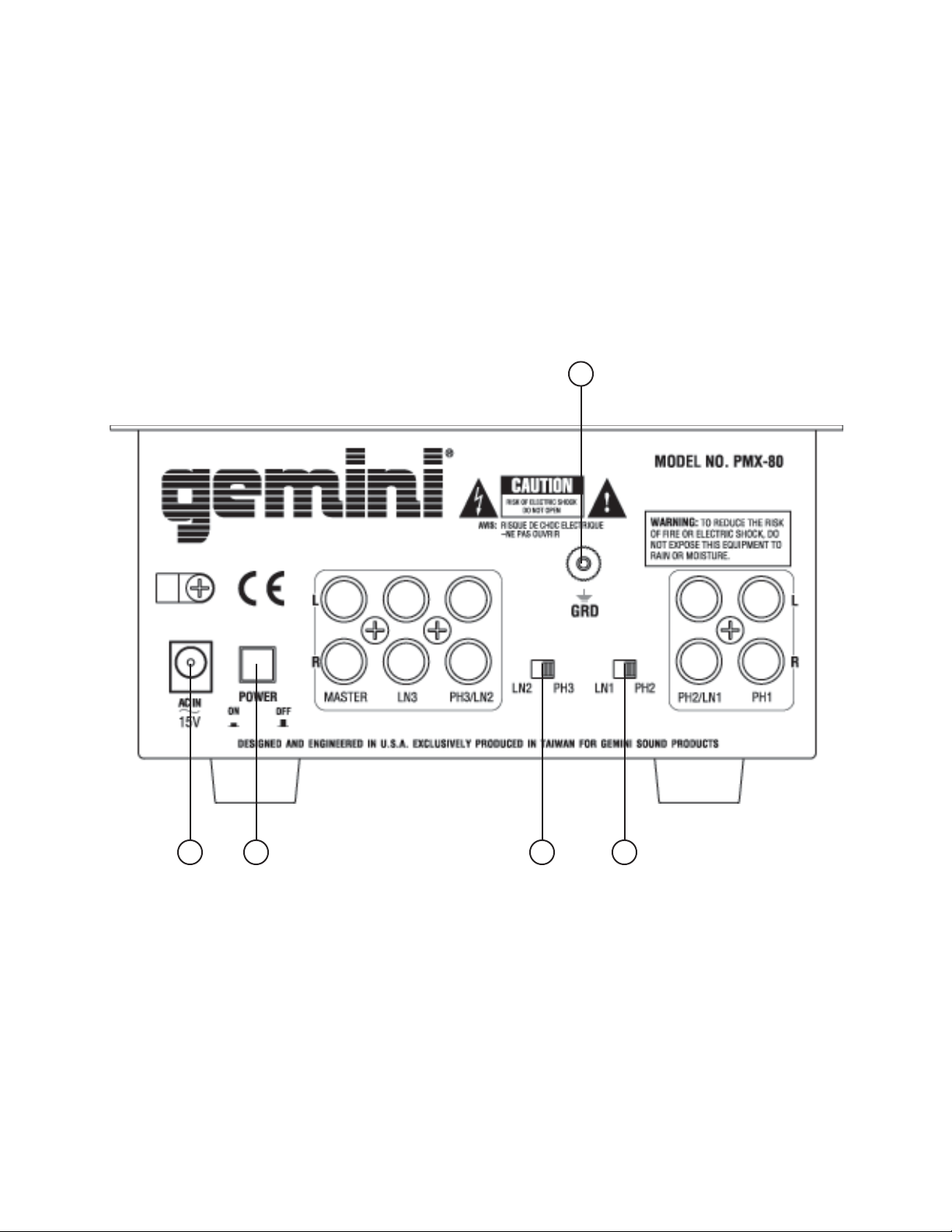
Connections
1. Make sure that the POWER (6) switch is in the OFF position. This unit
comes supplied with a 15 volt AC adaptor. Plug the male pin of the
adaptor into the rear panel POWER JACK (7). Then plug the adaptor
into a proper power source.
2. The MASTER OUTPUT (1) jacks are unbalanced and used to connect
to your main amplifier.
3. The DJ MIC (18) input (found on the front panel) accepts a 1/4"
connector and balanced and unbalanced microphones.
4. On the rear panel are 2 stereo PHONO/LINE (3, 4) inputs, 1 stereo
PHONO (5) input and 1 stereo LINE (2) input. The PHONO/LINE
SWITCHES (8, 10) enable you to set the (3, 4) inputs to Phono or Line.
The phono inputs will accept only turntables with a magnetic cartridge.
A GROUND SCREW (9) for you to ground your turntables is located on
the rear panel. The stereo line inputs will accept any line level input
such as a CD player, a cassette player, etc.
5. Headphones can be plugged into the front panel mounted PHONES
(36) jack.
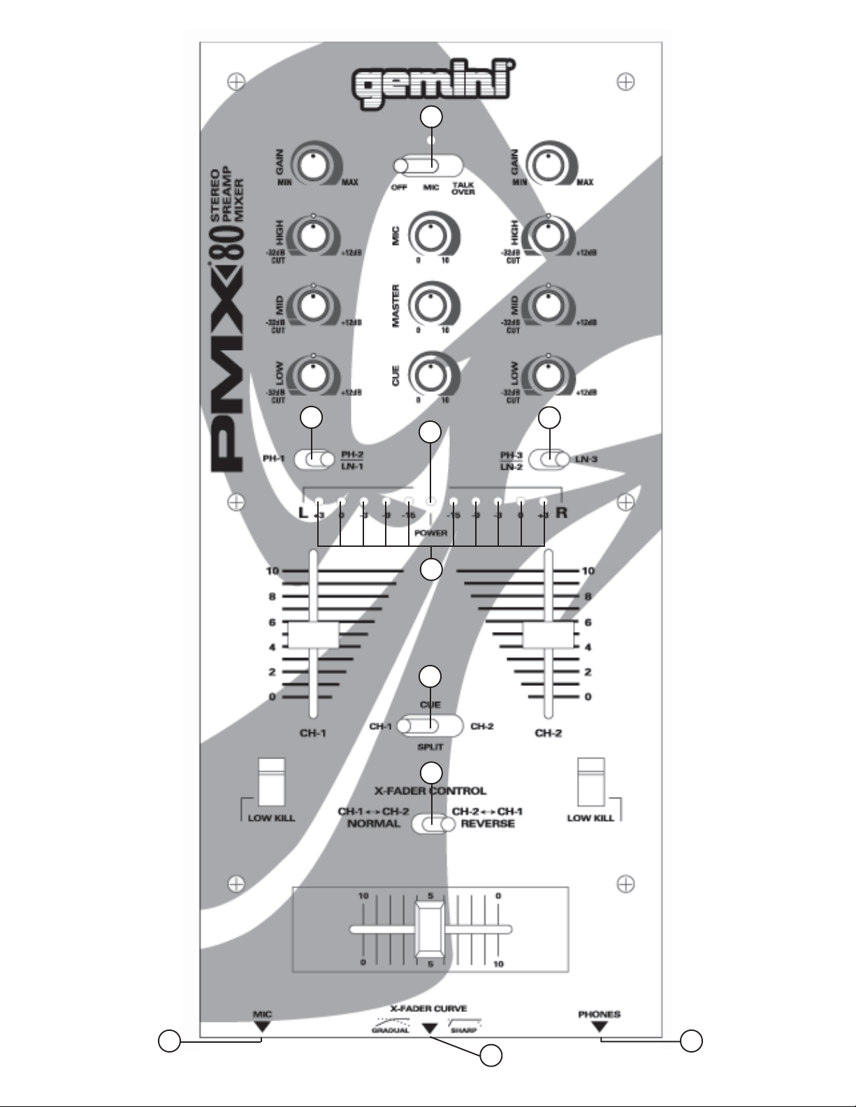
Operation
1. POWER ON: Once you have made all the equipment connections to
your mixer, press the POWER (6) switch. The power will turn on and
the POWER LED (23) will glow RED.
2. CHANNEL 1: The GAIN (11), HIGH (12), MID (13), and LOW (14)
controls allow you to fully adjust the selected source. Switch # (15)
allows you to select either the PHONO 1 (5) or the PHONO 2/LINE 1
(4) input. The CHANNEL SLIDE (16) controls the output level of this
channel.
3. CHANNEL 2: The GAIN (29), HIGH (30), MID (31), and LOW (32)
controls allow you to fully adjust the selected source. Switch # (33)
allows you to select either the PHONO 3/LINE 2 (3) or the LINE 3 (2)
input. The CHANNEL SLIDE (34) controls the output level of this
channel.
4. KILLING LOW FREQUENCIES: You can use the Kill Feature on each
channel to remove Low band frequencies to create special effects
and improve your mix. Move the KILL SWITCH (17) down to remove
the low band of Channel 1 from your mix. Move the KILL SWITCH
(35) down to remove the low band of Channel 2 from your mix.
5. CROSSFADER SECTION: The CROSSFADER (27) allows the mixing of
one source into another. The left side of the CROSSFADER (27) is
CHANNEL 1 and the right side is CHANNEL 2. The CROSSFADER (27)
in your unit is removable and if the need arises can be easily replaced.
Crossfader units are available in three varieties. Part # RF-45 (which
is identical to the crossfader supplied with the mixer) has a 45 mm
travel from side to side. Part # RF-30 is available with a 30 mm travel
distance. Also available is the PSF-45 with a special curve designed
for scratch mixing. Just purchase one of these crossfader units from
your Gemini dealer and follow these instructions:
1. Unscrew the outside FADER PLATE SCREWS (B). Do not
touch the INSIDE SCREWS (C).
2. Carefully lift the fader and unplug the CABLE (D).
3. Plug the new fader into the cable and place it back in the
mixer.
4. Screw the fader to the mixer.
The CROSSFADER CURVE SWITCH (28) allows you to adjust the kind
of curve the crossfader has. When the switch is in the left position,
the curve is gradual and gentle. When the switch is in the right
position, the curve is steep and cutting (perfect for scratching). The
CROSSFADER REVERSE SWITCH (26) allows you to reverse the
crossfader so that CHANNEL 2 is controlled by the left side of the
crossfader and CHANNEL 1 is controlled by the right side of the
crossfader.
NONO
TETE
NO
TE: When the
NONO
TETE
(26) (26)
(26) is activated (moved to the right), only the crossfader
(26) (26)
reverses. The Channel Slides, Gain, Kill Switches and tonal
controls do not reverse.
6. OUTPUT CONTROL SECTION: The level of the MASTER OUTPUT (1) is
controlled by the MASTER (21) control.
7. TALKOVER SECTION: The purpose of the talkover section is to allow
the program playing to be muted so that the mic can be heard above
the music. The MIC/TALKOVER (19) switch has three settings. When
the MIC/TALKOVER (19) switch is in the left position, the mic and
talkover are both off. When the MIC/TALKOVER (19) switch is in the
center position the mic is on, the MIC INDICATOR will glow, but
talkover is off. When the MIC/TALKOVER (19) switch is in the right
position, the mic and talkover will be on and the volume of all sources
except the Mic input are lowered by 16 dB. MIC LEVEL (20) controls
the level of the MIC.
8. CUE SECTION: By connecting a set of headphones to the PHONES
(36) jack, you can monitor either channel or both together. Move the
CUE SWITCH (25) to the left to monitor CHANNEL 1. Move the CUE
SWITCH (25) to the right to monitor CHANNEL 2. Move the CUE
SWITCH (25) to the center position to split the signals from each
channel so that CHANNEL 1 will be heard in one earphone and
CHANNEL 2 will be heard in the other earphone. Use the CUE LEVEL
(22) control to adjust the headphone volume without effecting the
overall mix.
9. DISPLAY: The DISPLAY (24) indicates the MASTER output.
CRCR
CR
CRCR
OSSFOSSF
ADER REVERSE SWITADER REVERSE SWIT
OSSF
ADER REVERSE SWIT
OSSFOSSF
ADER REVERSE SWITADER REVERSE SWIT
CHCH
CH
CHCH
Specifications
INPUTS:
DJ Mic..............................................................1.5mV 600 Ohm
Phono.........................................................................3mV 47Kohm
Line.......................................................................150 mV 27Kohm
OUTPUTS:
Amp.................................................................0 dB 1V 400ohm
Max..............................20V Peak to Peak
GENERAL:
Low (Channels 1 - 2)........................................................+ 12dB/-32 dB
Mid (Channels 1 - 2).........................................................+ 12dB/-32 dB
High (Channels 1 - 2).....................................................+ 12dB/-32 dB
Gain (Channels 1 - 2)...........................................................0 to -20dB
Frequency Response....................................20Hz - 20KHz +/- 2dB
Distortion................................................................................0.02%
S/N Ratio...............................................................better than 80dB
Talkover Attenuation..............................................................-16dB
Headphone Impedance.........................................................16ohm
Power Source........................................................115V/15V AC 7.5W
230V/15V AC 7.5W
Dimensions.......................................6.5” x 14” x 3” (165 x 355 x 85 mm)
Weight........................................................................................5 lbs (2.27 kg)
Page 4
Page 5

Parts Lists
Item #
1
2
3
4
5
6
7
8
9
10
11
12
13
14
15
16
17
18
19
20
21
22
23
24
25
26
Cabinet Parts and Packing
Description
PANEL CONTROL
PANEL REAR
BOTTOM COVER
BRACKET VR (SUB CHASSIS)
HOLDER FADER
KNOB SWING (LONG)
KNOB PUSH (SMALL)
KNOB SLIDE (BIG)
KNOB ROTARY (B TYPE)
INLAY KNOB (BLACK)
INLAY KNOB (GRAY)
INLAY KNOB (RED)
TRIM VR
HOLDER LED (3f 17mm)
PAD FOOT
DUST PROOF CLOTE-VR
SWING DUST PROOF CLOTH
GND SCREW
BUSHING WIRE
BAND-HEAD TAPPING SCREW/TW-E 3×6(AB)
FLAT-HEAD TAPPING SCREW 3f×6(AB)
BAND-HEAD TAPPING SCREW 3×6(AB)
FLAT-HEAD TAPPING SCREW 3f×12(AB)
BAND-HEAD TAPPING SCREW 3f×5(AB)
BAND-HEAD TAPPING SCREW (TWIN) 3f×8 (AB)
PAN-HEAD MACHINE SCREW 2.6f×4(B)
Part #
002-223
034-020
032-027
021-776
022-367
023-674
002-531
002-704
003-110
148-236
148-239
148-238
003-970
003-969
049-206
159-171
159-216
146-710
049-190
121-003A
111-043A
111-046A
111-049A
111-051A
110-172A
102-025
Printed Circuit Boards
Item #
1
PRINTED CIRCUIT BOARD PMX80-1
2
PRINTED CIRCUIT BOARD PMX80-2
3
PRINTED CIRCUIT BOARD PMX80-3
Description Part #
262-073
262-074
262-075
Page 5
Page 6

Parts Lists - PCB1 Input Output
Item #
Item #
Designators
1
IC1, IC2, IC3
2
IC5
3
IC4
Designators Description Part #
D3, D4
1
D1, D2
2
SW3
3
J4
4
J1
5
J2
6
ICs
Description Part #
INTEGRATED CIRCUIT NJM2068LD
INTEGRATED CIRCUIT NJM7912FA
INTEGRATED CIRCUIT NJM7812FA
Electrical Parts
RECTIFIER DIODE 1N4002 (1N4003,1N4004)
ZENER DIODE 1/2W 12V
SLIDE SWITCH
DC JACK 2.5
4P RCA JACK
6P RCA JACK
074-145
074-114
074-107
079-027
079-012
081-038
092-135
161-105
161-106
Parts Lists - PCB2 Main
Item #
1
2
3
4
Item #
1
2
3
4
5
6
ICs
Designators
IC4
IC10
IC1-2, IC6,
IC8, IC9
IC3, IC7
INTEGRATED CIRCUIT NJM2068LD
INTEGRATED CIRCUIT NJM4556AD
INTEGRATED CIRCUIT NJM4558LD
INTEGRATED CIRCUIT OR LB1423N
Description Part #
074-145
074-100
074-104
074-154
Electrical Parts
Designators Description Part #
D9-12
SW4
SW2, SW5, SW7
VR3, VR9
VR8
VR6
LIGHT EMITTING DIODE (GREEN) 3.15f
SLIDE SWITCH
LEVER SWITCH 4P2C
ROTARY VR 16f L=20 GAIN 10KA×2
ROTARY VR 16f L=20 MIC 50KA
ROTARY VR 16f L=20 MASTER, 500KA×2
080-104
081-038
082-019
071-161
071-066
071-158
Page 6
Page 7

Page 8

Page 9

Schematic
R69
47
R45
47
+VCC
-15 -9 -3 0 +3 -15 -9 -3 0 +3
D12
LED
D11
LED
D10
LED
D9
LED
D8
LED
D1
LED
D2
LED
D3
LED
D4
LED
D5
LED
MIC OFF
RED RED
GREEN
GREEN
GREEN
RED RED
GREEN
GREEN
GREEN
MIC ON
TALKOVER
+VCC
-VCC
MASTER
J2C
X4
X2
R41
430
R44
47K
R68
47K
C33
10/16
R74
IC7
LB1403N
9
C52
6
8
4
5
3
7
2
1
9
6
8
4
5
3
7
2
1
IC3
LB1403N
SW3D
VR8
50KA
C35
R26
1K5
C21
154
R14
R27
33K
VR4A
50KEx2
C17
154
R34
3K6
R31
1K5
30K
R50
30K
0.47/16
R78
4K3
-VCC
R75
10K
C53
10/16
C30
0.47/16
R38
4K3
R42
10K
C29
10/16
R76
300K
R72
300K
C50
10/16
1
IC4A
2068LD
4 8
IC3-4
IC3-8
2
3
C40
22P
C46
10/16
R55
3K3
7
IC4B
2068LD
68P
6
5
C41
68P
R48
30K1 1%
R56
30K1 1%
R40
1K 1%
R47
1K 1%
C16
22/16
C7
22/16
123
MIC
J1
C1
10/16
1
IC1A
4558LD
C22
56P
4 8
IC7-8
IC7-4
2
3
C20
682
C3
562
4K7
R25
24K
R12
8K2
R8
5K6
R11
33K
C14
103
VR1A
VR2A
50KEx2
50KEx2
R23
2K4
R24
33K
C26
10/16
1
IC2A
4558LD
4 8
R19
5K6
IC5-8
C8
IC5-4
181
2
3
R9
R4
2K
C23
10/16
VR5A
VR3A
10KAx2
1
C44
IC6A
VR6A
SW3C
R18
1K5
VR4B
R32
3K6
R33
1K5
100K
50KA
R21
1K
4558LD
500KA
4 8
IC2-4
IC2-8
2
3
VR6B
C38
6.8P
SW3A
R59
4K3
D6
+VCC -VCC
CURVE
SW1A
C19
C25
154
R17
4K7
R30
33K
50KEx2
C27
154
VR1B
R28
500KA
C31
10/16
SW3B
R73
390K
LED
R39
75K
R37
75K
R53
75K
SW6A
R61
75K
R58
4K3
R79
4K3
SW1B
182
182
C18
R51
20K
R62
20K
C6
10/16
7
IC1B
4558LD
C4
56P
6
5
C12
682
C11
562
R16
24K
R13
8K2
R7
5K6
R20
33K
C15
103
VR2B
50KEx2
50KEx2
2K4
R29
33K
C28
10/16
7
IC2B
4558LD
R15
5K6
C9
181
6
5
R1
2K
C24
10/16
VR5B
GAIN CH-1
VR3B
10KAx2
R22
C32
R10
50KA
1K
R66
430
C48
7
6.8P
6
5
10/16
R77
390K
SW6B
100K
-VCC
10/16
IC6B
4558LD
NORM/REV
R82
1K5
R86
VR10A
50KEx2
R94
3K6
R83
1K5
R57
1K
X-FADER
X-F
C57
33K
C54
D7
LED
POWER
65432
R
X3
SW5A SW5B SW5C SW5D
1 -2 \ 2 -1
C61
56P
IC8-8
154
C68
562
R85
4K7
R104
5K6
R103
33K
154
VR12A
VR13A
50KEx2
50KEx2
R90
2K4
C59
181
R95
5K6
IC6-8
R87
2K
IC4
1
L
SW6C
SW8B
C67
C79
10/16
1
IC8A
4558LD
R101
4 8
IC8-4
2
3
C62
682
R93
24K
VR10B
R108
8K2
C70
103
R92
R84
R107
33K
C56
10/16
1
IC9A
4558LD
4 8
IC6-4
2
3
R110
100K
C77
10/16
VR11A
50KA
1K
VR9A
10KAx2
R97
X4X3
C15
22/16
22/16
22/16
Z 12VD1Z 12V
1
2
J4
-VCC
R125
7
4558LD
5
R105
8K2
C69
R106
33K
C55
7
IC9B
6
5
C73
VR11B
20K
10/16
C71
R109
103
10/16
4558LD
C45
100/16
R113
R3
R115
R6
R65
R70
682
24K
10/16
10KAx2
10
C65
IC8-4
10
C13
IC7-4
10
C78
IC6-4
10
C2
IC5-4
10
C43
IC3-4
10
C51
IC2-4
CUE LEVEL
R111
100K
50KA
R98
1K
22/16
R19
10
-3
C34
22/16
R37
10
-VCC
-2
C10
22/16
R10
10
-1
C46
1/50
3
Vout
GND
1
Vin
IC5
7912
2
C47
1000/25
SW3A
R47
750
D4
1N4002
22/16
22/16
22/16
22/16
22/16
22/16
+VCC
R122
10
C82
220/16
C80
22P
R118
20K
+VCC
R67
10
C49
22/16
IC5A
C36
22P
2
VR7A
50KA
C39
SW4C
R46
43K
-VCC
R123
R120
47
1
4556
IC10A
4 8
2
3
-VCC
R116
2K
1
R54
4558
C34
4 8
3
47/16
CH1
SW4A SW4B
R52
43K
CUE
J2
123
R121
47
10
220/16
7
C83
IC10B
4556
C81
22P
R119
20K
6
5
R117
2K
7
10
22/16
IC5B
4558
C45
22P
50KA
6
5
VR7B
C42
47/16
CH2
SPL
SW4D
R60
43K
R63
SW4
43K
R27
10
+VCC
7812
C22
+3
R30
10
C27
+2
R2
10
C3
+1
C43
1/50
3
Vout
GND
2
Vin
1
C44
1000/25
C48
100/16
POWER
D2
R48
750
SW3B
D3
1N4002
AC15V-JACK
+VCC
R114
10
C72
22/16
IC8-8
R2
10
C5
22/16
IC7-8
R102
10
C64
22/16
IC6-8
R5
10
C10
22/16
IC5-8
R49
10
C37
22/16
IC3-8
R71
10
C47
22/16
IC2-8
R36
75K
R35
75K
R43
75K
R64
75K
SW6D
R81
4K3
R80
4K3
SW8A
C66
182
182
R124
20K
1K5
R89
50KEx2
3K6
1K5
C76
IC8B
C75
56P
6
C58
154
C74
562
R112
4K7
33K
R99
5K6
R100
33K
C63
154
VR12B
VR13B
50KEx2
50KEx2
R91
2K4
R96
5K6
C60
181
R88
2K
GAIN CH-2
VR9B
MAIN PCB
IN/OUT PCB
R13
R9
R12
C5
SW2A
PH1;PH2\LN1
C12
10/16
R14
1K
1
C11
273
IC1A
2068LD
100K
4 8
+1
-1
2
3
C9
822
8K2
C8
56
R8
1K
R11
47K
180
47/16
J1A
PH1
SW2B
SW2C
X1
X1
C7
R3
7
IC1B 2068LD
5
C4
56
R4
R7
47K
SW2D
10/16
1K
C2
6
C6
1K
R1
C1
47/16
C19
10/16
C13
10/16
R25
1K
R15
7
C23
273
273
R5
100K
R26
100K
6
822
180
5
C18
822
R6
8K2
R24
8K2
R23
R28
180
C24
47/16
1K
1
IC2A
2068LD
+3
-3
IC2B
2068LD
48
2
3
C21
56
C16
56
1K
R20
1K
R22
47K
R16
47K
C20
47/16
J1B
PH2/L2
PH2/L2
SW1A
SW1B
SW7A
LN3;PH3\LN2
C36
C14
273
R18
100K
R41
100K
C17
822
C33
R21
8K2
R40
8K2
180
R39
R17
180
C29
47/16
SW2A
PH3/L2
SW7B
SW7C
X5
X2
C35
10/16
R42
1K
1
273
2068LD
IC3A
+2
2
3
822
R36
SW2B
SW7D
C30
10/16
R31
1K
C37
10/16
C40
7
C26
4 8
-2
IC3B 2068LD
6
5
C31
C32
56
C28
56
1K
1K
R32
R38
47K
R34
47K
C25
47/16
J2A
PH3/L2
10/16
273
R33
100K
C38
101
C39
101
822
R35
8K2
R29
180
R431KR44
1K
J2B
L3
Page 8
 Loading...