

Page 1
SERVICE MANUAL
CDX-802
Professional CD Player
CONTENT’S:
Connections & Operations:.......................................................Page 2-4
Specifications:..............................................................................Page 4
Parts Lists:.................................................................................Page 5-7
PCBs:........................................................................................Page 8-11
Schematics:..........................................................................Page 12-19
Gemini Sound Products Corp.
120 Clover Place P.O. Box 6928
Edison, NJ 08818-6928
732-738-9003 (Phone) • 732-738-9006 (Fax)
Page 1
Page 2
13
123
123
123
123
18
12
CDX-802
7
6
11
10
14 16
23
15
17
9
8
21
19
22
20
25
4
5
3
DIGIT AL OUTPUT 2
24
CONNECT TO
REMOTE CONTROL 2
2
R
OUTPUT 2
230V
50HZ
1
2
L
115V
60H
AC IN
Z
FUSE 250V, FO. 5AL
FUSE 250V, F1 AL
(2)
CONNECT TO
REMOTE CONTROL 1
1
DIGIT AL OUTPUT 1
R
OUTPUT 1
L
Page 3

INTRODUCTION:
Congratulations on your purchase of a Gemini CDX-802 CD Player.
Your state-of-the-art professional CD Player is backed by a three year
warranty that excludes lasers, which are covered by a separate one
year warranty. Prior to use of this unit, we suggest you carefully read
the following intructions.
Y our Gemini CDX-802 CD Player comes equipped with ADCS (Automatic
Disc Calibration System), a unique state-of-the-art feature. CDs are
produced by a variety of manufacturers and recorded by many different
professional companies as well as the do-it-yourselfers at home. Therefore,
all CDs do not play the same. The ADCS automatically adjusts the laser in
your CDX-802 CD Player for each individual CD you insert into the tray, to give
you the best possible performance for every CD you play regardless of how it
was manufactured or how it was recorded. With this exclusive system you
always get consistent and reliable performance as well as exceptional
sound quality every time you play a CD... any CD.
CAUTIONS:
1. Do not use this CD player at temperatures below 41°F/5°C or higher than
95°F/35°C.
2. The apparatus should not be exposed to dripping or splashing, and no objects
filled with liquids such as vases should be placed on the apparatus.
3. Place the unit in a clean and dry location.
4. Do not place the unit in an unstable location.
5. When disconnecting the power cord from an AC outlet, always grasp it by
the plug. Never pull the power cord.
6. To prevent electric shock, do not remove the cover or the bottom screws.
There are no user serviceable parts inside. Please refer servicing to a
qualified technician.
7. Do not use chemical solvents to clean the unit.
8. Keep the laser pickup clean by keeping the tray closed.
9. Keep this manual in a safe place for future reference.
SAFETY CERTIFICATIONS:
Laser Diode Properties
Material: Ga - Al - As
Wavelength: 755 - 815 nm (25° C)
Laser Output: Continuous Wave, max. 5mWCAUTIONS
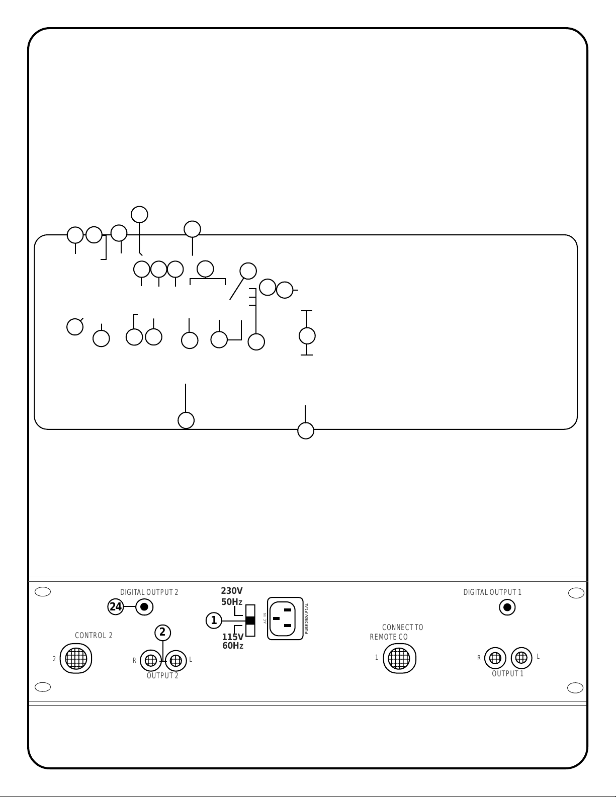
LINE VOLTAGE SELECTION:
The Gemini CDX-802 CD Player is a dual voltage unit operating at
115 or 230 volts. Be sure to set the proper voltage:
1. Place the head of a screwdriver in the center of the VOLTAGE
SELECTOR (1) switch found on the rear panel.
2. Slide the switch to 115 or 230 volts.
3. Do not force or twist the switch. Excessive force may cause damage.
If the switch does not move smoothly, contact a qualified technician.
CONNECTIONS:
1. Plug one end of a set of RCA connectors into the two LINE OUTPUT
JACKS (2) on the back of your CD unit.
2. Plug the other end of the RCA connectors into any of the available
line level input jacks on your mixer. If you are playing the CDX-802
through a receiver, you can plug the RCA connectors into the CD or
AUX INPUT JACKS located on the receiver. If there are no CD or AUX
INPUTS, use any line level (not phono) input.
FUNCTIONS:
POWER SWITCH:
switch is properly set, plug the unit in and press the POWER (3) button.
The unit will turn on. Pushing POWER (3) a second time turns the unit off.
DISC TRAY:
unloading and playback. Pressing OPEN/CLOSE (4) opens or closes
the tray. The DISC TRAY (5) holds both 12 cm and 8 cm CDs and
automatically closes after remaining open for three minutes.
NOTE: TRAY WONT OPEN WHEN THE CDX-802 IS IN THE PLAY MODE.
OPEN/CLOSE:
DISC TRAY (5).
After making sure the VOLTAGE SELECTOR (1)
The DISC TRAY (5) is where the CD is held during loading,
Press OPEN/CLOSE (4) to load or remove a CD from the
DISPLAY:
PLAYBACK DISPLAY:
PLAY/PAUSE :
TRACK SKIP
SEARCH JOG WHEEL:
SEARCH DIAL:
STOP :
TIME:
FLY CUE:
CUE:
LOOP:
BOP/RELOOP:
SINGLE-AUTO CUE/CONTINUOUS:
PITCH:
PITCH BEND :
(3)
The DISPLAY (6) shows total tracks; track number; pitch value;
single-auto cue; continue (continuous play); and three different time
displays: track time elapsed, track time remaining and total time remaining
on disc. Time is measured in minutes, seconds and frames.
play time remaining for each track. The display flashes slowly when
the track has 15 seconds remaining and pulses rapidly when play
time is down to five seconds.
to change from PLAY to PAUSE or PAUSE to PLAY.
the track to play.
functions. Use the SEARCH
in PAUSE mode. Use the SEARCH JOG WHEEL (10) to bend the pitch
for precise synchronization in PLAY mode.
direction and speed of your CD. Turning the dial in a clockwise
direction scans forward while a counter-clockwise turn scans
the track in reverse. Scan speed increases as the dial is turned.
The STOP (12) button ends CD play.
The TIME (13) button switches the time display between the
three available choices listed under DISPLAY (6).
The FLY CUE (14) function lets you set cues “on the fly” with the
press of a button. Press FLY CUE (14) when the disc reaches the musical
location you wish to make your cue or start point. The cue point is now
programmed. Press CUE (15) to return to the cue point. Press PLA Y/PAUSE
(16) and the unit starts from the pre-programmed spot.
With the unit in the PLAY mode (PLAY/PAUSE LED is green) and
after the cue point has been programmed, pressing CUE (15) will
cause the CD player to enter the PAUSE mode (green PLAY/PAUSE
LED blinks) at the programmed cue point (the CUE LED glows yellow).
Holding down the CUE (15) button changes the function to PREVIEW
and starts the CD from the programmed cue point. Releasing the CUE
button (15) will return the CD laser to the preset cue point.
After a cue point is memorized, pressing the B/EXIT (16) button in
PLAY mode, (the CUE LED blinks yellow), repeats the section between
the cue point and the point where the B/EXIT (16) button was pressed.
Press the B/EXIT (16) button again or pause play to exit the repeating
play.
return to a previously saved loop from normal play, press the BOP/
RELOOP (17) button after saving the loop. To return to and instantly play
from a previously saved cue point, press the BOP/RELOOP (17)
button after setting the cue point (if you do not have a loop saved).
CONTINUOUS (18) activates the AUTO CUE FUNCTION. The AUTO
CUE causes the CD to pause at the recorded beginning of the next track
and allows you to start play into the next song with no space in
between songs. Pressing SINGLE-AUTO CUE/CONTINUOUS (18) a
second time will activate the CONTINUOUS function. This causes the
CD to repeat play continuously until SINGLE-AUTO CUE/CONTINUOUS
(18) is pressed a third time to deactivate the CONTINUOUS function.
Pushing the PITCH button (19) activates the PITCH section of the
unit (PITCH LED glows red). The pitch of the CD will change according
to the position of the PITCH SLIDE (20).
automatically raise the pitch up to +4% or lower the pitch down to
-4% from the existing setting. Releasing the buttons returns pitch to the
original setting. Use this function to match the pitch bend when mixing
from one song to another.
The PLAYBACK DISPLAY (7) displays the
Each press of PLAY/PAUSE (8) causes the operation
:
The TRACK SKIP (9) buttons let you select
The SEARCH JOG WHEEL (10) has two
JOG WHEEL (10) to make fine adjustments
Use the SEARCH DIAL (11) to select the scanning
The BOP/RELOOP (17) button has two functions. To
Pressing SINGLE-AUTO CUE/
Pushing the PITCH BEND (21) buttons will
Page 4

4%, 8% and 16%:
percent the pitch control slide will have. The 4% button will assign +/4% to the PITCH CONTROL SLIDE (20). The 8% button will assign +/8% to the PITCH CONTROL SLIDE (20). The 16% button will assign +/16% to the PITCH CONTROL SLIDE (20). The PITCH (19) must be ON
for the 4%, 8% and 16% (22) buttons to work.
INSERT:
Set a cue point (using the CUE (15), FLY CUE (14) or SEARCH
JOG WHEEL (10). From this cue point you will be able to sample up to
10 seconds of a musical phrase or sound. When you push and hold the
INSERT (23) button you will be able to insert that phrase or sound at
any spot in the music that is currently playing, replacing what is playing
in that spot with up to 10 seconds of the piece you have sampled.
When you release the INSERT (23) button the music will continue
uninterrupted.
Use the 4%, 8% and 16% (22) buttons to assign the
ROBO START INSTRUCTIONS:
IN SINGLE-AUTO CUE MODE:
Use ROBO ST ART (25) in SINGLE-AUTO CUE MODE to alternate play
between the CDX-802’s two CD players (one track from one side, then
one from the other). In SINGLE-AUTO CUE MODE play starts
immediately with no blank or “dead” space. ROBO START (25) causes
one side of the CD player to play when the other side is paused.
1. Engage SINGLE-AUTO CUE MODE with the SINGLE-AUTO CUE/
CONTINUOUS (18) button .
2. Press the ROBO START (25) button to activate ROBO START (25). Play
will alternate between the two CD players. At the end of a track, the
playing side pauses and the other CD deck plays a track. At the end of
this track, the playing side pauses and the first CD deck resumes play.
NOTE: YOU CAN ONLY USE YOUR “SAMPLE” WITH YOUR CURRENT
CD. ONCE YOU OPEN THE DISC TRAY TO CHANGE CDS, YOUR
“SAMPLE” WILL BE AUTOMATICALLY DELETED.
DIGITAL OUTPUT JACK:
DRIVE, or other such items which accept digital signals to the BNC
(24) output connector on the rear panel of your CDX-802 allows you
to record a digital signal from CD.
Connecting any type of DAT, MD, HARD
OPERATING INSTRUCTIONS:
1. Make sure that the VOLTAGE SELECTOR SWITCH (1), found on the
rear panel, is set for the proper voltage. Plug the unit in and press the
POWER SWITCH (2). The unit is ON. Pushing POWER (1) a second
time turns the unit OFF.
2. Press OPEN/CLOSE (4) and place a CD in the DISC TRAY (5). Press
OPEN/CLOSE (4) again. The tray will close.
3. Push TRACK SKIP (9) to select the track you wish to play.
4. Press PLAY/PAUSE (8) and the unit will instantly play.
FLY CUE & CUE INSTRUCTIONS:
The FLY CUE (14) function lets you set cues “on the fly” with the press
of a button. Press FLY CUE (14) when the disc reaches the musical
location you wish to make your cue or start point. The cue point is now
programmed. Press CUE (15) to return to the cue point. Press PLAY/
PAUSE (8) and the unit instantly starts from this pre-programmed spot.
AND/OR:
1. To pre-program a cue point (the spot on a CD at which you want play to
start) select the proper track and push PLAY/PAUSE (8) so the unit
enters the PLAY mode (PLAY/PAUSE LED glows green). When the CD
reaches the approximate musical spot you wish to make your cue, push
PLA Y/P AUSE (8) so the unit enters the PAUSE mode (PLAY/PAUSE LED
blinks). Move the SEARCH JOG WHEEL (10) forward or in reverse until
the precise spot at which you want CD play to begin is located. Push
PLAY/PAUSE (8). The cue point is now programmed. Press CUE (15) to
return to this pre-programmed cue point at any time. Push PLAY/PAUSE
(8) and the unit will instantly play from the pre-selected spot.
2. To fine tune your pre-programmed cue point, push PLAY/PAUSE (8)
so the unit enters the PLAY mode. Push the CUE button (15) and the
CD will return to the cue point you programmed in step #1 and begin play
from that point. If you decide this cue or starting point is okay, leave the
unit alone until you are ready to play.
3. If, however, the selected spot is not exactly where you want it, push
the CUE (15) button while the CD is playing and the disc will return to
the pre-programmed cue point. Locate the
which you want play to start by turning the SEARCH JOG WHEEL (10).
Push PLAY/PAUSE (8) to pre-program this new cue point. Press the
CUE (15) button to pause play at the new cue point. Push PLAY/
PAUSE (8) at any time and the unit will play from the pre-selected spot.
exact
spot on the CD at
IN CONTINUOUS MODE OR DURING NORMAL PLA Y :
If you use the ROBO START (25) function without SINGLE-AUTO CUE
MODE (in CONTINUOUS MODE or during normal play), CD deck play does
not alternate automatically. The PLAY/PAUSE (8) button must be pressed
on the playing deck for the second deck to play.
1. During normal play, set a cue point on the second CD deck.
2. Press the ROBO START (25) button to activate ROBO START.
3. Press PLAY/PAUSE (8) button on the playing side to start play
from the cue point on the other CD deck.
NOTE: PAUSING PLAY IN THE MIDDLE OF A TRACK CAUSES THE
OTHER CD DECK TO PLAY. WHEN THE NEW TRACK ENDS, PLAY
RESUMES ON THE FIRST CD PLAYER FROM THE POINT AT WHICH
IT WAS PAUSED.
TROUBLESHOOTING:
• If a disk will not play, check to see that it was loaded correctly (label side up)
and that the CD unit is on a flat, level, stable surface. Check disc for dirt,
scratches, spills, etc.
• If the disc spins but there is no sound, check the cable connections. If they are
okay, check your amplifier or receiver.
• If the CD skips, check it for dirt, oil or scratches. Do not assume
that the CD player or laser is defective. Many CDs are recorded “out of spec” and
skip on most or all CD players. Before sending the unit to an authorized Gemini
service technician, insert a disc that plays properly in another unit.
SPECIFICATIONS:
GENERAL:
Type................................................................................Compact Disc Player
Disc Type.........................................Standard Compact discs (12 cm & 8 cm)
Time Display..............................Track Elapsed, Track Remain, or Total remain
Instant Start...................................................................Within 0.015 seconds
Track Selection.........................................................................1 to 99 Tracks
Installation..........................................................................................19" each
Dimensions.............................................................................19” x 3.5” x 10”
Weight Per Unit.....................................................................................9.5 lbs.
AUDIO SECTION:
Quantization...........................................16 Bit Linear/Channel, 3 Beam Laser
Oversampling Rate..............................................................................8 Times
Sampling Frequency...........................................................................44.1 kHz
Frequency Response.............................................................20 Hz to 20 kHz
Digital Output.........................................................................................IEC958
Total Harmonic Distortion.....................................................Less Than 0.05%
Signal to Noise Ratio.............................................................................100 dB
Dynamic Range.......................................................................................96 dB
Channel Separation...................................................................90 dB (1 KHz)
Output Level...........................................................................1.9 Volts R.M.S.
Power Supply.............................................................AC 115/230V, 60/50 Hz
Specifications and design are subject to change without notice for purpose of improvement.
NOTE: IF YOU PRESS OPEN/CLOSE (4) WHEN A DISC IS BEING READ AFTER LOADING, THE
DISC TRAY WILL P AUSE, FOR A MOMENT BEFORE OPENING.
(4)
Page 5
ITEM
PART NUMBER
1
2
3
4
5
6
7
8
9
10
11
12
13
14
15
16
17
18
19
20
21
22
23
24
25
26
27
28
29
30
31
32
33
34
35
36
37
38
39
40
41
42
43
44
45
46
48
49
50
51
012-054
031-040
032-128
021-604
041-479
022-860
041-480
003-737
002-573
003-743
002-576
003-739
003-711
047-494
148-316
049-215
153-213
196-165
255-238
257-020
156-089
190-062
099-167
099-168
099-169
099-014
099-214
099-232
099-233
099-234
160-008
160-009
160-044
160-052
121-002A
111-046A
110-172A
101-043
110-078
111-030
111-044A
111-057
131-081
170-396
262-393
262-291
262-394
262-395
094-204
003-605
PART NUMBER
092-083
092-083
079-027
059-236
074-074
074-186
074-085
PART NUMBER
092-147
074-074
092-148
CDX-802 (MAIN )
Q’TY
ENGLISH NAME
1
PANEL CONTROL
1
TOP COVER
1
BOTTOM COVER
1
SUB PANEL
1
HEAT SINK
2
MOUNTING BRACKET
2
HEAT SINK (C)
2
DESK DOOR
1
KNOB PUSH (DA)
1
PUSE KEY INLAY (DA)
1
KNOB PUSH KEY ASS’Y (C)
2
PR OTECTOR INLAY
1
HOLDER LED 3Æ (7mm)
6
PCB SUPPORT
1
MANE PLATE (SMALL)
8
PAD FOOT
1
POLYFORM
3
SERIAL NO:LABEL
1
GIFT BOX
1
OWNER’S MANUAL
1
WARRANTY CARD
1
SILICON GEL
1
A LABEL
1
J LABEL
1
V LABEL
1
LABEL -MADE IN TAIWAN
1
LABEL- MADE IN CHINA
2
LABEL- GREEN
2
LAABEL-RED
2
LABEL-YELLOW
1
PE BAG 85×100mm
1
PE BAG 230×300mm
1
PE BAG 160×250mm
1
PE BAG 650x650mm
16
BAND-HEAD TAPPING SCREW
14
BAND-HEAD TAPPING SCREW
6
BAND-HEAD TAPPING SCREW/TWIN SCREW 3×8(AB)
3
FLAT-HEAD MACHINE SCREW3×8(B)
2
PAN-HEAD TAPPING SCREW-2 4×6(B)
1
PAN-HEAD TAPPING SCREW4×6(B)
4
BAND-HEAD TAPPING SCREW ( “NUT” ) 3×10(AB)
6
FLAT-HEAD TAPPING SCREW 3×6(Z)
3
NUT/WASHER 3mm
MASTER CARTON
2
PRINTED CIRCUIT BOARD CDX802-1
1
PRINTED CIRCUIT BOARD CD01-4
1
PRINTED CIRCUIT BOARD CDX802-2
2
PRINTED CIRCUIT BOARD CDX802-3
2
16P FLAT CABLE 110mm P=1mm
7
CABLE TIES CV-100
PCB 802-2
COMMENT
TO AC CORD
TO TRANSF.
1N4002
UH962021
7805
M317
79L05
PCB 802-7
COMMENT
MINI DIN(092-147)
NJM7805
PLUG08(092-148)
FOOTPRINT
0.156"-2
0.156"-2
DIODE10
EMC1
TO-220
TO-220
TO-92
FOOTPRINT
MINI_DIN
TO-220
X8
PARTS LIST:
ITEM
PART NUMBER
1
2
3
4
5
6
7
8
9
10
11
12
13
14
15
16
17
18
19
20
21
22
23
24
25
26
27
28
29
30
31
32
33
34
35
PART NUMBER
074-182A
092-150A
074-183B
Q’TY
DESIGNATORS
1
X2
1
X6
6
D1, D2,D3, D4, D5, D6
1
EMC1
1
IC3
2
IC1, IC4
1
IC2
Q’TY
DESIGNATORS
1
1
1
X4
IC4
X3
Page 5
074-104S
092-153A
092-154A
092-151A
092-152A
092-026A
092-050A
012-053
031-041
021-605
021-606
003-427
003-428
002-572
003-141
003-144
002-720
148-316
003-738
003-739
003-711
002-579
002-575
002-576
003-741
159-227
099-252
099-253
153-212
196-165
099-014
099-214
190-062
160-045
110-172A
111-046A
121-002A
111-057
262-396
262-397
262-398
262-286
074-187
058-021
058-022
079-003
079-027
079-003
074-194
074-195
074-196
092-147
074-179
074-184
074-192
161-173
074-181
074-191
076-104
076-137
076-095
CDX-802 CONTROL BOX
Q’TY
ENGLISH NAME
1
PANEL CONTROL
1
COVER
1
TOP ANGLE
1
BOTTOM ANGLE
2
PLATE LAMP
2
LAMP HOLDER
1
KNOB PUSH (CA)
2
KNOB ROTARY (A)
2
KNOB ROTARY (B)
2
KNOB SLIDE
1
MANE PLATE (SMALL)
2
VR INLAY (CA)
2
PR OTECTOR INLAY
14
HOLDER LED 3
2
KNOB PUSH KEY ASS’Y (A)
2
KNOB PUSH KEY ASS’Y (B)
1
KNOB PUSH KEY ASS’Y (C)
2
PUSE KEY INLAY (CA)
2
VR DUST PROOF CLOTH (CA)
2
LAMP PAPER
2
LAMP LABEL
1
POLYFORM
1
SERIAL NO:LABEL
1
LABEL- MADE IN TAIWAN
1
LABEL- MADE IN CHINA
1
SILICON GEL
1
PE BAG 160×650mm
4
BAND-HEAD TAPPING SCREW/TWIN SCREW3×8(AB)
4
BAND-HEAD TAPPING SCREW3×6(AB)
20
BAND-HEAD TAPPING SCREW3×5(AB)
6
FLAT-HEAD TAPPING SCREW3×6(Z)
1
PRINTED CIRCUIT BOARD CDX802-5
1
PRINTED CIRCUIT BOARD CDX802-6
2
PRINTED CIRCUIT BOARD CDX802-7
2
PRINTED CIRCUIT BOARD CD01-8
PCB 802-1
COMMENT
BA6392FP
SM5902AF
16.9344MHZ
16MHz
1N4148
1N4002
1N4148
SOCKET16
MM74HCT00M
MM74HCT32M
74HCT157M
DTN
NT511740C5J
PCM1717E
P89C557E4
CXD3068Q
161-173
4558LD
BA6218
CXA2550N
2SA1317
2SA954
2SC2878
2SC536
083-061
PLUG02
PLUG03
PLUG05
PLUG06
PLUG08
PLUG03
PLUG08
FOOTPRINT
BA6392FP
C505
CRYSTAL
CRYSTAL
D10
DIODE10
DIODE6
FPC-16
M14A
M14A
M16A
MINI_DIN
NT511740
PCM1717
QFP80-2
QFP-80P
RCA2A
SIP8
SIP9
SSOP20
TO-92
TO-92
TO-92
TO-92
WP001
X2MM-2
X2MM-3
X2MM-5
X2MM-6
X2MM-8
X3
X8
φφ
φ (7mm)
φφ
Q’TY
DESIGNATORS
IC2
1
IC9, IC8
2
CR1
1
CR2
1
D3
1
D1
1
D11,D8, D7, D2
4
X1
1
IC15
1
IC14
1
IC13, IC12
2
X9
1
IC11,IC10
2
IC6
1
IC7
1
IC3
1
J1
1
IC5
1
IC4
1
IC1
1
Q6
1
Q1
1
Q3, Q2
2
Q4
1
SW1
1
X12
1
X6
1
X3
1
X2
1
X4
1
X5
1
X8
1
Page 6
PART NUMBER
079-003
079-003
074-171C
083-116
074-180
080-119
080-118
080-062
074-193
082-042A
082-042A
082-042A
082-042A
082-042A
082-042A
082-042A
082-042A
082-042A
082-042A
082-042A
082-042A
082-042A
082-042A
082-042A
082-042A
082-042A
082-042A
072-112i
001-081
092-044A
092-148
COMMENT
1N4148
1N4148
PIC16C505
JOG/SHUTTLE
LC75854E
GREEN
RED
YELLOW
TC74HC595AFN
16%
4%
8%
B/EXIT
BOP/RELOOP
CUE
FLY_CUE
INSERT
PITCH
PITCH-
PITCH+
PLAY/PAUSE
SGL ACUE
SKIP 10
SKIPFWD
SKIPREV
STOP
TIME
10KB
LCD40
SOCKET02
SOCKET08
PCB 802-5
FOOTPRINT
DIODE10
DIODE6
DIP14
JOG/SHUTTLE
LC75854E
M16A
RS60112
UTN-H241JV
LED
LED
LED
PB1
PB1
PB1
PB1
PB1
PB1
PB1
PB1
PB1
PB1
PB1
PB1
PB1
PB1
PB1
PB1
PB1
PB1
X2
X8
QUANTITY
1
3
1
1
1
1
4
1
1
1
1
1
1
1
1
1
1
1
1
1
1
1
1
1
1
1
1
1
1
1
1
DESIGNATORS
D4
D1, D2
IC1
SW6
IC2
LED4
LED7, LED6
LED2
IC4
SW3, LED3
SW1
SW2, LED8
SW9
SW10
SW8
SW18
SW23
SW15
SW14
SW17
SW11
SW5
SW16
SW13
SW12
SW7
SW4
VR1
IC3
X1
X2
PART NUMBER
079-003
079-003
074-171C
083-116
074-180
080-119
080-118
080-062
074-193
082-042A
082-042A
082-042A
082-042A
082-042A
082-042A
082-042A
082-042A
082-042A
082-042A
082-042A
082-042A
082-042A
082-042A
082-042A
082-042A
082-042A
082-042A
082-042A
082-042A
082-042A
082-042A
072-112i
001-081
092-044A
092-148
COMMENT
1N4148
1N4148
PIC16C505
JOG/SHUTTLE
LC75854E
GREEN
RED
YELLOW
TC74HC595AFN
16%
4%
8%
B/EXIT
BOP/RELOOP
CUE
FLY_CUE
INSERT
OPEN
OPEN_1
OPEN_2
PITCH
PITCH-
PITCH+
PLAY/PAUSE
ROBO
SGL ACUE
SKIP 10
SKIPFWD
SKIPREV
STOP
TIME
10KB
LCD40
SOCKET02
SOCKET08
PCB 802-6
FOOTPRINT
D12
DIODE6
DIP14
JOG/SHUTTLE
LC75854E
LED
LED
LED
M16A
PB1
PB1
PB1
PB1
PB1
PB1
PB1
PB1
PB1
PB1
PB1
PB1
PB1
PB1
PB1
PB1
PB1
PB1
PB1
PB1
PB1
PB1
RS60112
UTN-H241JV
X2
X8
QUANTITY
1
3
1
1
1
3
4
1
1
1
1
1
1
1
1
1
1
1
1
1
1
1
1
1
1
1
1
1
1
1
1
1
1
1
1
DESIGNATORS
D1
D2, D3, D4
IC1
SW6
IC2
LED4, LED1, LED5
LED3, LED6, LED7, LED8
LED2
IC4
SW20
SW21
SW19
SW9
SW10
SW8
SW18
SW22
SW3'
SW3
SW1
SW15
SW14
SW17
SW11
SW2
SW5
SW16
SW13
SW12
SW7
SW4
VR1
IC3
X1
X2
Page 6
Page 7

CD01-8-PCB
D1
X5
L1
L2
L3
Page 8

802-7-PCB
COPYRIGHT
X6
X4
X3
2001
C7
C9
IC4
GEMINI
110
C8
Page 9

19
CDX802-5 PCB-Left Side
IC1
22
SW4
11
7
6
4
R2
R3
R4
R5
10
9
R6
C1
33
SW5
12
C2
R7
SW6
R12
13
SW7
14
15
R8
R10
R11
R9
24
1
16
2
3
54
25
SW18
18
C3
R16
R17
R15
R14
SW23
IC3
34
SW9
30
28
R18
35
R13
C4
63
61
17
60
LED2
SW8
46
26
SW10
27
62
D1
41
IC2
SW12
20
5
LED4
19
SW11
D3
38
D2
D4
42
45
44
51
SW13
29
32
39
23
37
43
LED3
47
21
52
40
SW15
36
SW14
31
SW16
48
50
LED8
57
59
LED6
LED7
R21
SW3
SW17
58
R22
R20
R19
56
R23
SW1
49
SW2
C6
C5
X2
55
8
53
IC4
VR1
X1
Page 10

CDX-802-6 Right Side PCB
SW4
X1
LED1
SW1
6
R1
LED5
SW2
31
SW3'
8
27
SW3
7
IC1
R2
R3
R4
R5
2
3
4
22
9
C1
33
SW5
11
10
13
12
C2
R6
R7
SW6
SW7
R12
24
50
58
16
R8
14
15
R9
R10
R11
SW18
25
C3
R15
R16
R17
17
75
18
68
SW22
IC3
44
35
R18
R14
R13
C4
76
74
70
23
5
SW9
LED2
266665
SW8
71
72
73
20
SW10
1
IC2
D1
D2
69
SW12
19
D3
21
46
LED4
52
SW11
D4
41
32
LED3
45
28
53
42
43
51
38
SW13
36
30
SW16
54
SW14
67
29
R20R19
55
48
SW15
37
56
LED7
R22
LED8
49
R23
R21
47
LED6
60
64
SW17
39
34
40
X2
X2'
63
C6
62
SW21
SW19
C5
SW20
IC4
57
59
61
VR1
Page 11

JP116
JP117
C101
TP1
TP5
TP3
C58
C61
JP19
JP17
C80
R44
C66
JP65
R64
JP64
JP2
JP27
C27
C49
R40
IC11
JP18
JP4
R84
C2
C40
Q2
J1
C59
C68
C64
JP20
R91
JP29
IC10
C25
C50
C4
R62
R75
C65
R69
R70
C77
IC9
C91
IC15 IC14
JP3
JP6
JP28
C75
JP26
IC5
JP63
R82
C26
R65
C73
JP112
JP8
R63
D8
R45
C3
JP113
JP67
JP9
JP7
JP30
IC8
R71
C5
JP22
JP11
JP12
C76
C78
Q3
C62
JP10
JP15
JP14
JP21
JP38
C24
C67
JP104
C60
R74
C7
D7
R72
JP16
C90
JP105
JP23
JP31
R55
R41
JP110
JP71
JP42
JP111
R87
JP80
JP43
JP33
C69
JP107
L1
C20
C6
JP98
JP32
JP34
R102
C84
R54
C79
IC6
R100
IC12
R76
R86
IC13
R98
R30
C87
C88
Q6
C39
R99
C48
D11
C63
R16
R79
L2
JP35
JP75
JP83
JP66
C10
C21
JP132
JP92
C85
CDX802-1N-Main PCB
X12
JP131
R95
JP47
JP72
C34
R78
Q4
JP108
JP52
R73
JP99
R12
R97
C8
R52
R77
R48
R59
JP45
R37
C81
JP24
R3
R96
JP88
JP101
JP109
JP36
JP13
R85
R60
JP102
JP100
R4
IC1
C94
R61
R88
R1
C29
C30
R80
JP50
C47
R15
C82
C12
C31
C99
L9
C103
C104
C105
C102
R50
JP103
X1
JP5
R25
R21
JP78
R2
JP62
R9
JP56
JP60
R42
R13
C14
R7
JP25
JP59
JP61
JP90
R81
R17
JP40
JP77
X8
R58
R38
JP95
JP114
R51
JP44
R83
R20
R39
R23
Q1
R14
JP57
JP79
R8
JP129
JP126
C44
C45
R43
JP93
C13
R57
JP81
JP115
JP130
R68
C51
C22
JP55
C28
C52
C46
C11
C1
C9
C43
JP76
JP46
JP124
R67
C55
JP53
JP54
R53
R36
R66
X6
C42
JP128
X5
JP68
R27
JP41
R18
C23
JP74
R34
R46
C70
JP125
C54
CR1
R22
R28
C92
C38
R26
C32
C01
C74
C98
C15
X4
C53
C37
JP121
R47
CR2
JP96
JP51
C17
R19
IC3
JP58
C36
IC2
C97
R10
C18
JP127
JP82
JP94
JP84
C72
JP117
R35
JP85
JP87
JP89
JP70
JP73
R32
JP49
R49
C89
JP69
C95
IC7
SW1
JP106
R6
C41
C16
JP37
C33
D1
X9
C86
C56
C101
R101
C35
JP133
C19
IC4
C83
JP122
D3
JP97
JP123
C93
JP116
JP86
R24
R31
R92
C100
JP119
D2
JP120
JP91
R89
C96
C57
R11
JP1
JP118
R33
C71
R90
R5
R56
X2
R29
X3
Page 12

OPEN SW PCB
P
O
X1
D1
SW1
W
E
R
DGND
3
LED
2
1
OPEN/CLOSE 1
3
2
SW2
OPEN/CLOSE 2
DGND1
1
CDX802-4-Schematic
X2
Page 13

Power Schematic
X2
TO AC CORD
X5
X3
IC1
1
C10
4700/16
2
C18
2200/16
M317
3
Vin
C4
C9
104
IC3
7805
Vin
Vout
GND
2
IC2
79L05
Vin
Vout
GND
1
D1
1N4002
D2
L2
0uH
D3
1N4002
D4
1N4002
D5
1N4002
D6
1N4002
1N4002
X1
6
L1
5
0uH
4
3
2
1
C2
223
C3
223
C17
0.1K/250V
X6
TO TRANSF.
2
1
X7
CHASSIS
EMC1
UH962021
13
24
R2
C7
3M3
O.1K/250V
10000/16
C14
334
C13
334
1
2
SRV+
2
Vout
ADJ
R1
120
1
R3
C6
560
10/16
3
C15
104
3
C11
104
C16
100/16
C12
100/16
C1
470/16
C5
104
GND
2
1
-5V
5
4
3
IC4
M317
3
Vout
Vin
ADJ
1
R5
240
8
7
6
2
R4
120
C20
104
C19
10/16
C21
100/16
+5V
GND
D+3.6V
SRV+
-5V
X4
8
7
6
5
4
3
2
1
Page 14

X5
CDX802-8-Schematic
D1
1
1N4002
2
LAMP . PCB
L1 L2
L3
NOTES: L1;L2;L3 - DSPLAY LAMP 7V/42mA
Page 15

X3
1
2
PITCH A
PITCH B
A
CDX802-7-Schematic
3
B
4
GND
GND
H
5
DO OUT
CE CHIP ENABLE
D
6
E
7
CL CLOK
F
E
8
DA TRANS. DATA
G
H
G
D
GND
F
B
A
1
2
3
4
5
6
7
8
9
X4
MINI DIN
C9
104
+5V
IC4
7805
3
C8
100/16
Vout
GND
2
Vin
1
SRV +
X6
1
C7
100/16
2
C01DDIN0. PCB
SHASSIS
Page 16

IC3
LCD40
ROBO
CUE
PLAY/PAUSE
PITCH
16%
8%
4%
COM1
COM2
COM3
COM4
S0
S1
S2
S3
S4
S5
S6
S7
S8
S9
S10
S11
S12
S13
S14
S15
S16
S17
S18
S19
S20
S21
S22
S23
S24
S25
S26
S27
S28
S29
S30
+5V
1
2
3
4
5
6
7
8
9
10
11
12
13
14
15
16
17
18
19
20
21
22
23
24
25
26
27
28
29
30
31
32
33
34
35
LED2
YELLOW
LED4
GREEN
LED3
RED
LED8
RED
LED7
RED
LED6
RED
COM1
COM2
COM3
COM4
1
2
3
4
5
6
7
8
9
10
11
12
13
14
15
16
17
18
19
20
21
22
23
24
25
26
27
28
29
30
31
R18
220
R19
220
R20
220
R23
220
R22
220
R21
220
D4
1N4148
D3
1N4148
D2
45
KS346KS447KS5
KS1/S4044KS2/S41
S3/P3
S4/P4
3
4
1N4148
S2/P2
2
48
1
D1
1N4148
S1/P1
KS6
KI1
KI2
KI3
KI4
KI5
TEST
VDD
VDD1
VDD2
VSS
OSC
49
50
51
52
53
54
55
56
57
58
59
60
61
DO
62
CE
63
CL
64
DI
29 30 31
COM1
COM2
COM3
39
S3333S3434S3535S3636S3737S3838S39
28
32
S32
27
31
S31
26
30
S30
29
25
S29
28
24
S28
23
27
S27
26
22
S26
21
25
S25
20
24
S24
19
23
S23
18
22
S22
17
21
S21
16
20
S20
15
19
S19
14
18
S18
13
17
S17
16
10
11
12
IC4
TC74HC595AFN
1
Qb
2
Qc
3
Qd
4
Qe
5
Qf
6
Qg
7
Qh
8
GND
IC2
LC75854E
6
7
8
9
16
VCC
15
Qa
14
SER
13
/G
12
RCK
11
SCK
10
/SCLR
9
Q`h
COM4
43
COM140COM241COM342COM4
2
3
4
5
+5V
S55S66S77S88S99S1010S1111S1212S1313S1414S1515S16
1
C6
100/10
C5
103
C2
104
C1
104
SW6
JOG/SHUTTLE
8
JOG A
SW15
PITCH
SW14
PITCH-
SW10
BOP/RELOOP
SW1
4%
R13
62K
6
7
GND
JOG B
R14
1K
C4
681
5
SHUT D
4
GND
C3
33/10
R15
1K
3
SHUT C
R16
1K
R9
4K7
2
SHUT B
SW7
STOP
SW17
PITCH+
SW9
B/EXIT
SW2
8%
+5V
R10
4K7
1
SHUT A
R17
10
R11
4K7
R7
10KR610KR210KR310K
+5V
SW5
SGL ACUE
SW8
CUE
SW11
PLAY/PAUSE
13
12
11
10
9
8
R4
10KR510K
+5V
X2
IC1
Vss14VDD
RBO
RB1
RB2
RC0
RC1
RC2
8
SW16
SKIP 10
SW12
SKIPREV
SW18
FLY_CUE
SW3
16%
dldk01.sch
+5V
1
2
RB5
3
RB4
4
RB3
5
RC5
6
RC4
7
RC3
PIC16C505
6
7
SW4
TIME
SW13
SKIPFWD
X1
SW23
INSERT
+5V
R12
4K7
R8
220
3
4
5
VR1
4
2
10KB
1 3
+5V
1
2
OPEN_2
1
2
CDX802-5/DLDK Control Unit Left Side
Page 17

D4
R9
4K7
C3
33/10
3
BOP/RELOOP
R15
1K
R14
1K
4
GND
SW15
PITCH
SW14
PITCH-
SW10
SW21
4%
C4
681
5
JOG B6JOG A
SHUT D
1N4148
D3
1N4148
D2
Qb
Qc
Qd
Qe
Qf
Qg
Qh
GND
293031
S3333S3434S3535S3636S3737S3838S39
32
S32
S31
S30
S29
S28
S27
S26
S25
S24
S23
S22
S21
S20
S19
S18
S17
16
1
2
3
4
5
6
7
8
28
31
27
26
30
29
25
24
28
27
23
22
26
21
25
20
24
19
23
18
22
17
21
20
16
19
15
18
14
17
13
LED1
R1
10
GREEN
R18
220
R19
220
R20
220
R23
220
R22
220
R21
220
1N4148
D1
44
45
48
1N4148
49
KS6
50
KI1
51
KI2
52
KI3
53
KI4
54
KI5
55
TEST
56
VDD
57
VDD1
58
VDD2
R13
59
62K
8
7
GND
VSS
60
OSC
61
DO
62
CE
63
CL
64
DI
C2
104
C1
104
KS346KS447KS5
KS1/S40
KS2/S41
S1/P11S2/P22S3/P33S4/P44S55S66S77S88S99S1010S1111S1212S1313S1414S1515S16
123
C6
100/10
C5
103
COM4
43
COM4
+5V
COM2
COM3
41
42
COM2
COM3
IC2
LC75854E
4
COM1
40
COM1
5
16
15
14
13
12
11
10
9
39
6789101112
TC74HC595AFN
IC4
VCC
Qa
SER
/G
RCK
SCK
/SCLR
Q`h
+5V
SW7
STOP
SW17
PITCH+
SW9
B/EXIT
SW19
8%
R17
10
R11
4K7
R7
10KR610KR210KR310K
SW6
JOG/SHUTTLE
R16
1K
+5V
R10
4K7
SHUT A1SHUT B2SHUT C
8
PLAY/PAUSE
Vss
RBO
RB1
RB2
RC0
RC1
X2
SW5
SGL ACUE
SW8
CUE
SW11
SW2
ROBO
14
13
12
11
10
9
8
+5V
R4
10KR510K
SW4
TIME
SW13
SKIPFWD
X1
SW1
1
OPEN_2
2
VR1
10KB
X2'
2
1
5
4
3
8
7
6
SW3
OPEN_1
SW22
INSERT
+5V
4
2
1 3
+5V
1
2
3
SW16
SKIP 10
SW12
SKIPREV
SW18
FLY_CUE
SW20
16%
IC1
+5V
1
VDD
2
RB5
3
RB4
4
RB3
5
RC5
6
RC4
RC37RC2
PIC16C505
R12
4K7
R8
220
4
5
6
7
CDX802-6/SRDK-Control Panel Right Side
COM1
COM2
COM3
COM4
1
2
3
4
5
6
7
8
9
10
11
12
13
14
15
16
17
18
19
20
21
22
23
24
25
26
27
28
29
30
31
1
2
3
4
5
6
7
8
9
10
11
12
13
14
15
16
17
18
19
20
21
22
23
24
25
26
27
28
29
30
31
32
33
34
35
LED5
GREEN
LED2
YELLOW
LED4
GREEN
LED3
RED
LED8
RED
LED7
RED
LED6
RED
IC3
COM1
COM2
COM3
COM4
S0
S1
S2
S3
S4
S5
S6
S7
S8
S9
S10
S11
S12
S13
S14
S15
S16
S17
S18
S19
S20
S21
S22
S23
S24
S25
S26
S27
S28
S29
S30
LCD40
+5V
ROBO
CUE
PLAY/PAUSE
PITCH
16%
8%
4%
Page 18

A
IC13
2
1Y
7
LRCK_AB
2Y
9
ADATA_AB
3Y
12
DOUT
4Y
16
VCC
D+5V
C87
104
8
VSS
74HCT157M
DGND
IC12
4
1Y
7
2Y
9
SENSE_MC
3Y
12
EMPH_AB
4Y
16
VCC
D+5V
C88
104
8
VSS
74HCT157M
DGND
DOUT
R50
0
R58
D/O
100
R73
10K
R78
68
X12
Q4
2SC536
C12
103
R52
10K
C81
68
BCLK_B
3
1B
5
LRCK_A
2A
LRCK_B
6
2B
11
ADATA_A
3A
ADATA_B
10
3B
14
DOUT_A
4A
13
DOUT_B
4B
1
AB_OUT
A/B
15
G
DGND
2
1A
MX
3
1B
5
2A
6
2B
11
SENSE_MC_A
3A
10
SENSE_MC_B
3B
14
EMPH_A
4A
13
EMPH_B
4B
1
AB_OUT1
A/B
15
G
DGND
D+5V
R82
0
VCC
C91
C90
47/10
104
R840VDD
DGND
-5VD+5V
R76
R77
10
10
C99
2
R80
2K7
R79
560
C82
22/25
DGND
C31
104
C39
104
D
I
G
I
T
A
L
O
U
T
DGND
C73
IC11
104
13
14
VCC
RAS_B
WE_B
VSS
12
15
A3
A4
11
A2
A1
A0
A10
B1
B0
C61
104
DGND
DGND
C2
C1
C0
C10
D1
D0
DGND
10
9
8
6
5
4
3
2
1
C27
104
C25
104
NT511740C5J
13
12
11
10
9
8
6
5
4
3
2
1
A2
A1
A0
A10
NC
RAS
WE
DQ2
DQ1
VCC
IC10
VCC
A3
A2
A1
A0
A10
NC
RAS
WE
DQ2
DQ1
VCC
NT511740C5J
16
A5
17
A6
18
A7
19
A8
21
A9
22
OE
23
CAS
24
DQ3
25
DQ4
26
VSS
14
VSS
15
A4
16
A5
17
A6
18
A7
19
A8
21
A9
22
OE
23
CAS
24
DQ3
25
DQ4
26
VSS
D+5V DGND
RAS
WE
D+5V
D+5V DGND
D+5V
DGND
B2
B3
DGND
DGND
DGND
BCLK_A
1A
MX
4
BCLK_AB
C77
100/16
D+5V
DGND
A4A3
A5
A6
A7
A8
A9
CAS
CAS
DGND
C4C3
C5
C6
C7
C8
C9
CAS_B
D2
D3
CAS_B
EMPH_A
DGND
1
C62
104
UC12UC23UC34UC45UC56DIT
VDD2
44
A3
A3
43
A2
A2
42
A1
A1
41
A0
A0
40
A4
A4
39
A5
A5
38
A6
A6
37
A7
A7
36
A8
A8
35
A9
A9
34
NRAS
33
B1
WE
RAS
D+5V
C75
100/16
EMPH_B
DGND
1
C26
104
UC12UC23UC34UC45UC56DIT
VDD2
44
C3
A3
43
C2
A2
42
C1
A1
41
C0
A0
40
C4
A4
39
C5
A5
38
C6
A6
37
C7
A7
C8
36
A8
C9
35
A9
34
NRAS
33
D1
WE_B
RAS_B
IC9
SM5902AF
B2B3B0
IC8
SM5902AF
D2D3D0
XTIN
ADATA
DGND
DOUT_A
7
8
10
11
CLC9VSS
NTEST
12
LRCK
YLRCK
YSRDATA
13
BCLK
YSCK
ZSCK
ZLRCK
ZSRDATA
YFLAG
YFCLK
YBLKCK
NRESET
ZSENSE
VDD1
YDMUTE23YMLD24YMDATA25YMCLK26A1027NCAS28D229D330D031D132NWE
DGND
A10
LATCH_MC_A
DATA_MC_A
CLK_MC_A
CAS
ADATA
XTIN
DGND
DOUT_B
7
8
10
11
CLC9VSS
NTEST
YLRCK
YSRDATA
YSCK
ZSCK
ZLRCK
ZSRDATA
YFLAG
YFCLK
YBLKCK
NRESET
ZSENSE
VDD1
YDMUTE23YMLD24YMDATA25YMCLK26A1027NCAS28D229D330D031D132NWE
DGND
C10
LATCH_MC_B
DATA_MC_B
CLK_MC_B
CAS_B
14
15
16
17
18
DGND
19
20
21
22
C40
104
CLK_MC_A
DATA_MC_A
LATCH_MC_A
CLK_MC_B
DATA_MC_B
LATCH_MC_B
12
13
14
15
16
17
18
19
20
21
22
DGNDDGND
DGND
C24
104
B_SCOR
RESET1
SENSE_MC_A
D+5V
C80
100/16
LRCK
BCLK
B_SCOR
RESET1
C76
100/16
DGNDDGND
GFS
R91
SENSE_MC_B
D+5V
BCLK_A
LRCK_A
ADATA_A
47K
11
BCLK_B
LRCK_B
ADATA_B
GFS
6
8
3
6
3
D+5V
IC15B
IC14D
IC15A
IC14B
MM74HCT32M
IC14A
R102
RESET1
4K7
IC15D
MM74HCT00M
12
CLK_MC
DATA_MC
LATCH_MC
CLK_MC
DATA_MC
LATCH_MC
AB_IN
13
B_SCOR
11
4
5
IC14C
9
10
12
13
1
2
4
5
1
2
B
C
D
RF amplifier CXA2550N-Main Schematic
GFS_MC REMUVED
E
Page 19

TP1
R36
A
B
R37
XTIN
100
C22
100/6.3
C23
104
D/O
LRCK
ADATA
BCLK
EMPH
DGND
B_SQSO
B_SQSO
C
X5
R57
3
D+5V
1K
2
DGND
B_OP_CL
1
X6
3
B_RBS
SYNC
2
1
B_CNG
X4
1
+5V
2
B_PITCH_A
3
B_PITCH_B
4
5
B_DO
6
B_CE
7
B_CL
8
B_DI
X9
DTN
C
H
A
S
S
D
I
S
B_CE
1
2
SRV+
3
B_DI
4
B_DO
5
6
B_CL
7
B_PITCH_B
8
B_PITCH_A
9
X8
1
SRV+
2
SRVGND
3
4
DGND
5
R7
+5V
6
0
R8
7
0
-5V
R51
8
0
+3.6V
B_SCOR
C86 10/10
C93 10/10
AGND
R9
AGND
0
D+5V
A+5V
D+3.6V
B_CLOK
D+3.6V
C51
47
C52
47
D+5V
DGND
B_PITCH_A
DGND
D+5V
16.9344MHZ
B_PITCH_B
R89
10K
D+5V
CR1
B_CLOK
C32
100/6.3
C72
100/10
B_OPCLSW
R11
4K7
R33
4K7
B_LOADOUT
B_LOADIN
L_RES
+3.6V
C70
100/6.3
AGND
C28
104
R83
470K
61
DVDD2
62
ASYE
63
MD2
64
DOUT
65
LRCK
66
PCMD
67
BCK
68
EMPH
69
XTSL
70
DVSS2
71
XTAI
R18
1M
72
XTAO
73
SOUT
74
SOCK
75
XOLT
76
SQSO
77
SQCK
78
SCSY
79
SBSO
80
EXCK
C18
104
DGND
D+3.6V
L_RES
R10
D+5V
4K7
1
AGND
2
C95
3
104
4
5
A+5V
6
7
8
9
10
11
12
13
C101
C56
14
104
100/10
15
16
17
18
19
20
21
22
23
24
R24
R900R31
4K7
4K7
R5
0
DGND
RESET
+3.6V
C92
104
AGND
C45
473
R20
1M
R171MC44
221
R39
3K3
R38
3K3
54
55
56
60
PCO
BIAS57VCTL58V16M59VPCO
AVDD1
D
I
G
I
T
A
L
S
E
R
V
O
DVDD01XRST2MUTE3DATA4XLAT5CLOCK6SENS7SCLK8ATSK9WFCK10XUGF11XPCK12GFS13C2PO14SCOR15C4M16WDCK17DVSS018COUT19MIRR
B_CLOK
B_DATA
B_XLAT
B_SENS
L_RES
AVref-
AVref+
AVSS1
AVDD1
P5.7 IN
P5.6 IN
P5.5 IN
P5.4 IN
P5.3 IN
P5.2 IN
P5.1 IN
P5.0 IN
VSS1
VDD1
ADEXS
PWM0
PWM1
EW
P4.0
P4.1
P4.2
P4.3
RSTOUT
P4.4
B_SCLK
R32
R35
4K7
4K7
B_LSW
D+5V R66
R34 4K7
1
2
3
4
5
6
D+5V
DGND
80
76
XTAL479XTAL378AVSS277AVDD2
SELXTAL1
P4.525P4.626P4.727VDD228VSS229RSTIN30P1.031P1.132P1.233P1.334P1.435P1.536P1.637P1.738SCL39SDA
R92
0
C96
104
D3
1N4148
100/10
C71
D+5V DGND
C42
C46
152
103
C11
R42
4.7/6.3
10K
R23
10K
R53
R43
33K
100K
45
46
47
50
51
IGEN
ASYO48ASYI49RFAC
CLTV52FILO53FILI
IC3
CXD3068Q
R6
47K
R49
47K
B_CE
B_CL
220
P0.075P0.174P0.273P0.372P0.471P0.570P0.669P0.768VSS467VDD4
IC7
P89C557E4
C100
1/10
D+5V
AVSS1
B_DI
R67
R68
220
220
GFS_MC
SENSE_MC
B_DO
DATA_MC
GFS
B_OP_CL
LATCH_MC
B_RBS
AVDD0
CLK_MC
B_SCOR
B_CNG
B_LOCK
AVSS0
DGND
R101
47K
DGND
B_FOK
44
66EA65
P3.3/INT1
P3.2/INT0
P3.1/TXD
P3.0/RXD
SYNC
D+5V
ALE/WE
P3.5/T1
P3.4/T0
DGND
PSEN
XTAL1
XTAL2
RFDC43ADIO
P2.7
P2.6
P2.5
P2.4
P2.3
P2.2
P2.1
P2.0
VSS3
VDD3
N.C.
N.C.
P3.7
P3.6
40
42
D+5V
C74 100/10
C97 104
TE41CE
20
6
5
4
3
2
1
D+5V
1
2
3
4
5
6
64
63
62
61
60
59
58
57
56
55
54
53
52
51
50
49
48
47
46
45
44
43
42
41
C43
100
682
AGND
C48
C17
471
104
R22
C47
100K
471
40
SE
39
FE
38
VC
37
TES1
36
TEST
35
DVSS1
34
FRDR
FRDR
33
FFDR
FFDR
32
TRDR
TRDR
31
TFDR
TFDR
30
SRDR
SRDR
29
SFDR
SFDR
28
DVDD1
27
FSTO
26
SSTP
25
SNDL
MDP
24
LOCK
23
PWMI
22
FOK
B_LOCK
21
DFCT
B_FOK
B_LOCK
B_SENS
B_SCOR
B_SQSO
B_FOK
B_LOCK
10K
R46
R47
D+5V
4K7
LRCK_AB
B_LMUTE
AB_OUT
AB_OUT1
AB_IN
B_LDON
R19
1M
CR216MHz
C98 104
B_SQSO
B_DATA
B_XLAT
B_SCOR
B_CLOK
B_SENS
B_SCLK
DGND
C55
100/10
D+5V
C54 47
C53
DGND
47
R55
15K
DGND
C33
100/6.3
D+3.6V
C89
104
RF
TP3
VC
TP5
AGND
AGND AGND
R54
15K
R88
5K6
XTIN
EMPH
LRCK
ADATA
BCLK
B_LMUTE
DGND
R28
4K7
SRVGND
SRV+
R95
R15
150
2K2
R21
3K3
R98
C84
1M
1.0/6.3
R16
C85
1K
100/6.3
B_LDON
SRVGND
C36
27
C15
104
C38
SRVGND
334
C41
27
SRVGND
C16
C83
104
47/16
D+5V
D2
R56
1N4148
22K
RESETRESET
C19
10/16
DGND
B_LMUTE
L
O
W
18
19
20
-
>
M
U
XT OUT
ML/MUTE
CLK OUT
T
E
DAC
PCM1717E
D GND2B CLK IN6D IN5LRCIN
XT IN
VDD
C102
4
1
3
C21
102
A
104
C63
L2
3.3uH
100/6.3
R81
100
R59
100
R60
100
R61
100
47
DGND
VCVC
C34
82
R96
R97
51K
51K
FOCUS BIAS
IC1
11
TE
R
F
12
FE_BIAS
A
13
FE
M
P
14
RFM
15
R25
RFO
8K2
C10
16
RF_1
17
103
RFTC
18
AGCONT
19
LD_ON
20
VCC
C94
CXA2550N
104
C30
100/6.3
MOTOR DRIVER
FCS+
1
CH1OUT F
FCS- SNDL+
2
CH1OUT R
3
RC IN1
4
FRDR
CH1 RIN
5
FFDR
CH1 FIN
6
VREF IN
7
VREF OUT
IC2
BA6392FP
8
GND
9
TRDR
CH2 FIN
10
TFDR
CH2 RIN
11
RC IN2
TRK-
12
CH2OUT R
TRK+
13
CH2OUT F
GND14MUTE
SRV+
IC4
BA6218
FIN1GND2RIN3RES4GND5VCC6OUT27COM8OUT1
B_LOADIN
DGND
B_LOADOUT
B_OPCLSW
A
C7
10/10
13
12
11
MODE14RSTB
DC L
V OUT L
ZERO7A GND
D/C R
V OUT R
8
9
10
C6
10/10
L9
3.3uH
R48
100
R85
100
R99
100
R100
100
C60
100/6.3
C20
VCC
104
L1
3.3uH
+5V
D+5V
EMPH_AB
LRCK_AB
ADATA_AB
BCLK_AB
16
MC/DM117MD/DM0
IC6
15
4K7
R30
C10347C10447C105
+3.6V
AGCVTH
CH4OUT F
CH4OUT R
CH3 FIN
CH3 RIN
RC IN3
CH3OUT R
CH3OUT F
C57
100/10
C1
100/6.3
C13
104
VC
C14
C29
104
100/6.3
AGND
10
VC
9
EI
8
E
7
F
6
VEE
5
PD2
4
PD1
3
PD
2
LD
1
+3.6V
28
GND
27
26
25
VBIN
24
VSIN
23
VBIN
22
VCC
21
VCC
20
19
18
17
16
15
SRV+
L
O
A
D
I
N
G
C3
10/16
C5
10/16
C9
103
C8
100/6.3
VC
SNDL+
SNDL-
SNDL-
C37
SRV+
153
R26
33K
R27
SRV+
10K
SNDL
SNDL
SRDR
SFDR
C35
SLD+
152
SLD-
TRK+
TRK-
9
O
P
E
N
H
I
D1
D+5V
1N4002
R44
10K
R69
R40
R70
2K2
R72
2K2
2K2
3K3
C66
C68
272
102
R45
10K
R71
R41
2K2
3K3
C67
C69
272
102
Q1
2SA954
R14
22
R13
110K
R2
56K
R1
56K
R3
56K
R4
56K
R12
110K
C64
IC5B
331
6
5
4558LD
C65
331
IC5A
2
3
4558LD
48
C59
100/10
7
1
+5V
-5V
1N4148
X1
1
VC
2
VCC
3
E
4
D
5
A
6
B
7
C
8
F
9
AGND
LD
10
11
VR
12
PD
FCS+
13
TRK+
14
TRK-
15
FCS-
16
X2
SNDL-
1
SNDL+
2
SLD+
3
SLD-
4
5
DGND
6
B_LSW
X3
1
M+
2
M-
3
OPEN
4
DGND
R29
5
10K
CLOSE
C2
R64
220
10/16
C58
100/10
+5V
C4
R65
220
10/16
-5V
C78
100/16
D11
D8
1N4148
R74
560K
D7
1N4148
2SC2878
R87
470
R75
2M2
Q2
2SC2878
Q3
C79
220/16
R86
22K
2SA1317
R62
5K6
R63
5K6
Q6
RF amplifier CXA2550N-Main Schematic
GFS_MC REMUVED
AUDIO OUT
L
O
J1
U
C49
222
C50
222
T
ROUT
E
 Loading...