

Page 1
Your Gemini
User’s Manual
Not Intended
for Sale
Page 2
Gemini-10X, Gemini-15X: Star Mfg. Co., Ltd.
Trademark Acknowledgement
grafstar, Universal/Atari Parallel Interface,
Universal/Commodore Parallel Interface: Star Micronics, Inc.
Apple, Apple II, Apple II + , Apple Ile, Apple Ill, Applesoft: Apple Computer Inc.
Atari 400, Atari 800, Atari 850: Atari Inc., a Warner Communications Company
Commodore, VIC-20, C-64: Commodore Business Machines, Inc.
CPIM: Digital Research
IBM Personal Computer, IBM PC: International Business Machines Corporation
Microsoft BASIC: Microsoft Corporation
Osborne 1: Osborne Computer Corporation
TRS80: Radio Shack, a division of Tandy Corporation
0 1994, Star Mfg. Co., Ltd.
ii
-
Page 3
Congratulations on having purchased a serial, impact dot matrix printer that
offers you more quality, greater flexibility and convenience, and superior
reliability than you could find in any other printer in the same price range.
As you already know (or are about to learn), the Gemini-lox and
Gemini-15X let you print both regular and italicized alphabets, as well as
normal, elite (smaller), condensed, enlarged, emphasized, and double-strike
characters. You can print on regular stationery, multiple-sheet forms, fanfold computer paper, or paper fed from a roll (European style).
The graphics capability provided by the Gemini printers is limited only
by your graphic talents, and includes three bit-image modes: Low Resolution (60 by 72 dots per square inch), High Resolution (120 by 144) and Ultra
High Resolution (240 by 144). With all this printing power at your fingertips,
what are you waiting for? Let’s get started!
This User’s Manual is organized to serve both the first-time user and the
sophisticated computer buff. The first five chapters provide the basics you
need for putting your printer to work in most home and office applications.
Chapters 6 through 10 deliver information for intermediate and advanced
users, supported by technically rich appendices. If you are a beginner, you
might want to look at Chapters 6-10 sometime in the future, when your
curiosity about how the printer does what it does has replaced your initial
interest in what it can do.
Take a moment to examine the Table of Contents on the following page.
It shows you how this manual is organized to best serve your information
needs. You should note, if you are just now unpacking your new printer from
its shipment packaging, that Appendix G shows you what you have and how
it all fits together. This manual’s first several appendices are computerspecific, and help you connect your new Gemini with your computer. At the
back of this manual, there is a glossary that gives simple definitions of common terms. Following the glossary is an index to help you quickly find
answers to your questions.
A Quick-Reference Guide is printed on the inside folding flap of the back
cover. By reading this manual carefully, and practicing with your Gemini, you
should soon be able to achieve full printer performance just by referring to
this Quick-Reference Guide.
Congratulations on your purchase of a Gemini. May it work for you long
and well.
iii
Page 4
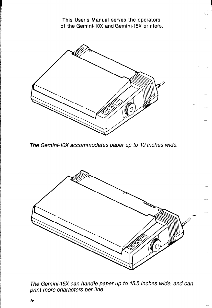
This User’s Manual serves the operators
of the Gemini-lox and Gemini-15X printers.
The Gemini-lox accommodates paper up to 10 inches wide.
The Gemini-15X can handle paper up to 15.5 inches wide, and can
print more characters per line.
iV
-
Page 5
Table of Contents
Chapter 1.
Chapter 2.
Chapter 3.
Chapter 4.
Chapter 5.
Chapter 6.
Chapter 7.
Chapter 8.
Chapter 9.
Chapter 10.
Appendix A.
Appendix B.
Appendix C.
Appendix D.
Appendix E.
Appendix F.
Appendix G.
Appendix H.
Appendix I.
Appendix J.
Appendix K.
Appendix L.
Appendix M.
Appendix N.
Appendix 0.
Glossary
index
Consumer Response
Reference Guide
Introduction
Paper and Ribbon
The Gemini Self-Test
Interfacing Gemini with Your Computer
Putting Gemini to Work for You
The Fundamentals of Dot Matrix Printing
The Full Range of Printing Capabilities
Downloadable Characters
The Function Codes
Maintenance
Apple II Plus
Atari 8001400
Commodore VIC-20, C-64
IBM-Personal Computer
Osborne
TRS80
When You First Get Your Gemini
ASCII Code Charts
ASCII Code Tables
International Character Sets
Character Style Tables
Control Circuit Block Diagram
Function Code Summary
Gemini’s Parallel Interface
Code Chart
1
13
39
47
57
81
99
115
123
143
151
165
179
192
194
206
217
226
230
231
232
241
242
246
254
258
261
Page 6
Page 7
INTRODUCTION
Allow us to introduce you to your Gemini printer: “Gemini, this is
your new user:’ “User, this is the remarkable new Gemini - a
versatile and dependable printer that lets you do tricks with the
a.“.
Ir.
c
A TOUR AROUND GEMINI
dot matrix and bit image capabilities?
In this chapter, we’ll answer the question: What are the parts
of the printer and how do they work together? We’ll define the
operating environment for Gemini, and we’ll discuss its technical
specifications. If you are just now unpacking your newly acquired
Gemini, refer to Appendix G to learn how the pieces fit together,
then return to this chapter to discover how to put your printer to
work for you.
; e.
L.
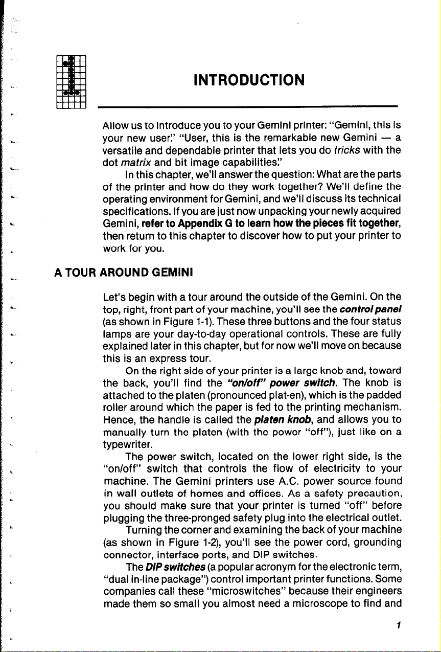
Let’s begin with a tour around the outside of the Gemini. On the
top, right, front part of your machine, you’ll see the controlpanel
(as shown in Figure l-l). These three buttons and the four status
lamps are your day-to-day operational controls. These are fully
explained later in this chapter, but for now we’ll move on because
b
this is an express tour.
On the right side of your printer is a large knob and, toward
the back, you’ll find the “on/off” power switch. The knob is
attached to the platen (pronounced platen), which is the padded
roller around which the paper is fed to the printing mechanism.
Hence, the handle is called the platen knob, and allows you to
manually turn the platen (with the power “off”), just like on a
typewriter.
The power switch, located on the lower right side, is the
“on/off” switch that controls the flow of electricitv to your
machine. The Gemini printers use A.C. power source found
in wall outlets of homes and offices. As a safety precaution,
you should make sure that your printer is turned “off” before
plugging the three-pronged safety plug into the electrical outlet.
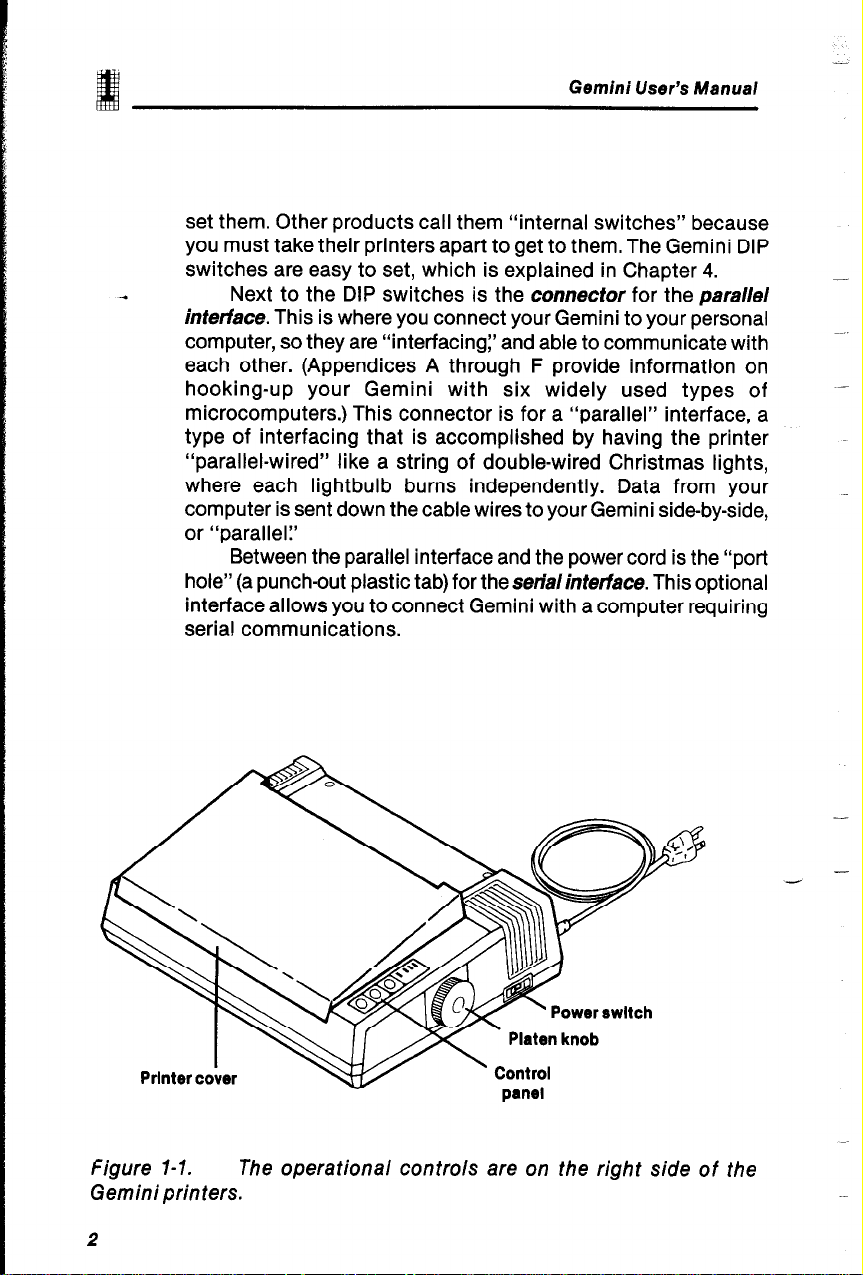
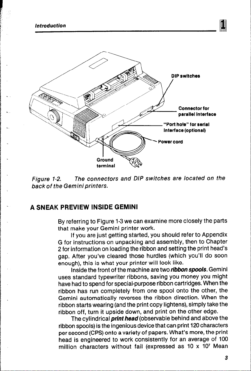
Turning the corner and examining the back of your machine
(as shown in Figure l-2), you’ll see the power cord, grounding
connector, interface ports, and DIP switches.
The DIPswitches (a popular acronym for the electronic term,
“dual in-line package”) control important printer functions. Some
companies call these “microswitches” because their engineers
made them so small you almost need a microscope to find and
Page 8
Gemini User’s Manual
set them. Other products call them “internal switches” because
you must take their printers apart to get to them. The Gemini DIP
switches are easy to set, which is explained in Chapter 4.
Next to the DIP switches is the connector for the parallel
interface. This is where you connect your Gemini to your personal
computer, so they are “interfacing:’ and able to communicate with
each other. (Appendices A through F provide information on
hooking-up your Gemini with six widely used types of
microcomputers.) This connector is for a “parallel” interface, a
type of interfacing that is accomplished by having the printer
“parallel-wired” like a string of double-wired Christmas lights,
where each lightbulb burns independently. Data from your
computer is sent down the cable wires to your Gemini side-by-side,
or “parallel?
Between the parallel interface and the power cord is the “port
hole” (a punch-out plastic tab) for the serialinterface. This optional
interface allows you to connect Gemini with a computer requiring
serial communications.
-
-
figure 1-1. The operational controls are on the right side of the
Gemini printers.
2
-
Page 9
Introduction
Grbund
terminal
DIP switches
Connector for
parallel Interface
“Port hole” for serial
Interface (optlonal)
-3%
Figure 1-2.
back of the Gemini printers.
A SNEAK PREVIEW INSIDE GEMINI
The connectors and DIP switches are located on the
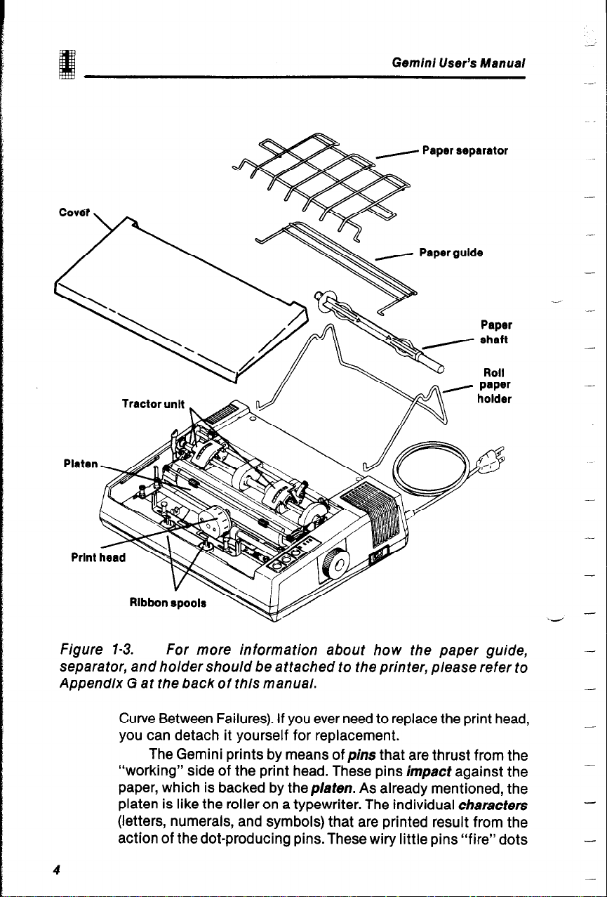
By referring to Figure 1-3 we can examine more closely the parts
that make your Gemini printer work.
If you are just getting started, you should refer to Appendix
G for instructions on unpacking and assembly, then to Chapter
2 for information on loading the ribbon and setting the print head’s
gap. After you’ve cleared those hurdles (which you’ll do soon
enough), this is what your printer will look like.
Inside the front of the machine are two ribbon spoo/s. Gemini
uses standard typewriter ribbons, saving you money you might
have had to spend for special-purpose ribbon cartridges. When the
ribbon has run completely from one spool onto the other, the
Gemini automatically reverses the ribbon direction. When the
ribbon starts wearing (and the print copy lightens), simply take the
ribbon off, turn it upside down, and print on the other edge.
The cylindrical print head (observable behind and above the
ribbon spools) is the ingenious device that can print 120 characters
per second (CPS) onto a variety of papers. What’s more, the print
head is engineered to work consistently for an average of 100
million characters without fail (expressed as 10 x 10’ Mean
e
3
Page 10
Gemini User’s Manual
Paper separator
Paper gulde
Figure 1-3. For more information about how the paper guide,
separator, and holder should be attached to the printer, please refer to
Appendix G at the back of this manual.
Curve Between Failures). If you ever need to replace the print head,
you can detach it yourself for replacement.
The Gemini prints by means of pins that are thrust from the
“working” side of the print head. These pins impact against the
paper, which is backed by the platen. As already mentioned, the
platen is like the roller on a typewriter. The individual characters
(letters, numerals, and symbols) that are printed result from the
action of the dot-producing pins. These wiry little pins “fire” dots
4
-
-
-
-
-
Page 11
Introduction
onto the paper, with the dots arranged according to preset matrix
patterns (imaginary grids). Because the characters are printed in
a series (one after the other), Gemini is called a serial, impact dot
matrix printer.
propelling fanfold computer paper. The tractor unit is used with
computer paper having perforated and punched paper guides on
the sides.
0 POWER
0 READY
DON LINE
0 PAPER
OUT
Above and behind the platen is a device for bearing and
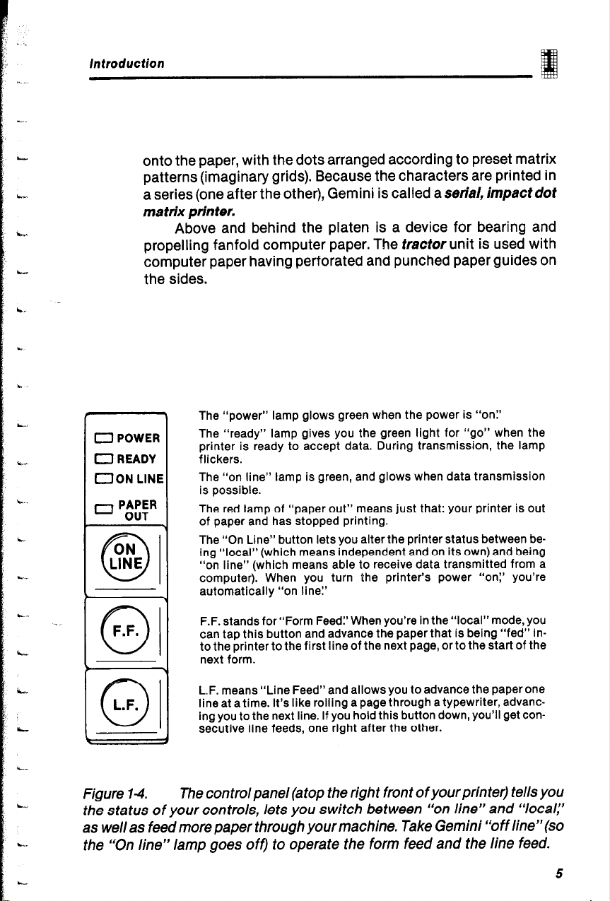
The “power” lamp glows green when the power is “on:’
The “ready” lamp gives you the green light for “go” when the
printer is ready to accept data. During transmission, the lamp
flickers.
The “on line” lamp is green, and glows when data transmission
is possible.
The red lamp of “paper out” means just that: your printer is out
of paper and has stopped printing.
The “On Line” button lets you alter the printer status between be-
ing “local” (which means independent and on its own) and being
“on line” (which means able to receive data transmitted from a
computer). When you turn the printer’s power “on:’ you’re
automatically “on line!’
F.F.
01
figure 14.
F.F. stands for “Form Feed:’ When you’re in the “local” mode, you
can tap this button and advance the paper that is being “fed” into the printer to the first line of the next page, or to the start of the
next form.
1
L.F. means “Line Feed” and allows you to advance the paper one
line at a time. It’s like rolling a page through a typewriter, advancing you to the next line. If you hold this button down, you’ll get consecutive line feeds, one right after the other.
-1
The control panel (atop the right front of your prin tetj tells you
the status of your controls, lets you switch between “on line” and “‘local,”
as well as feed more paper through your machine. Take Gemini “off line”(so
the “On line” lamp goes off) to operate the form feed and the line feed.
5
Page 12
Gem/d User’s Manual
TME CONTROL PANEL
Let’s turn our attention to the buttons and status lamps on the
.
control panel. Figure l-4 shows what the buttons and lamps can
do for you.
The two buttons in front are used to advance paper through
the printer, to the next line on which you want to print. L-Fadvances the paper one line at a time, and F.F. moves the entire
form (or page) forward.
The Online button allows you to switch between being
“online” (meaning hooked-up and in a data transfer mode) with
your computer, and being “local:’ Local means that the printer is
incommunicado - not in a communicating mode with your
computer.
A PRIMER OF YOUR PRINTER’S BASIC COMPONENTS
This section is provided for those of you who are new to computer
printer technology, and for now only want to know the most basic
information about how the Gemini works.
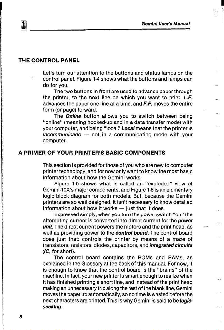
Figure l-5 shows what is called an “exploded” view of
Gemini-lox’s major components, and Figure 1-6 is an elementary
logic block diagram for both models. But, because the Gemini
printers are so well designed, it isn’t necessary to know detailed
information about how it works - just that it does.
Expressed simply, when you turn the power switch “on:’ the
alternating current is converted into direct current for the power
unit. The direct current powers the motors and the print head, as
well as providing power to the control board. The control board
does just that: controls the printer by means of a maze of
transistors, resistors, diodes, capacitors, and integratedcircuits
(IC, for short).
The control board contains the ROMs and RAMS, as
explained in the Glossary at the back of this manual. For now, it
is enough to know that the control board is the “brains” of the
machine. In fact, your new printer is smart enough to realize when
it has finished printing a short line, and instead of the print head
making an unnecessary trip along the rest of the blank line, Gemini
moves the paper up automatically, so no time is wasted before the
next characters are printed. This is why Gemini is said to be logic-
seeking.
-.
- -
-
-
6
Page 13
Introduction
Connector for
oarallel interface
board
Optional serial interface
(punch-out tab)
unit
Lower casing
- .
Power switch
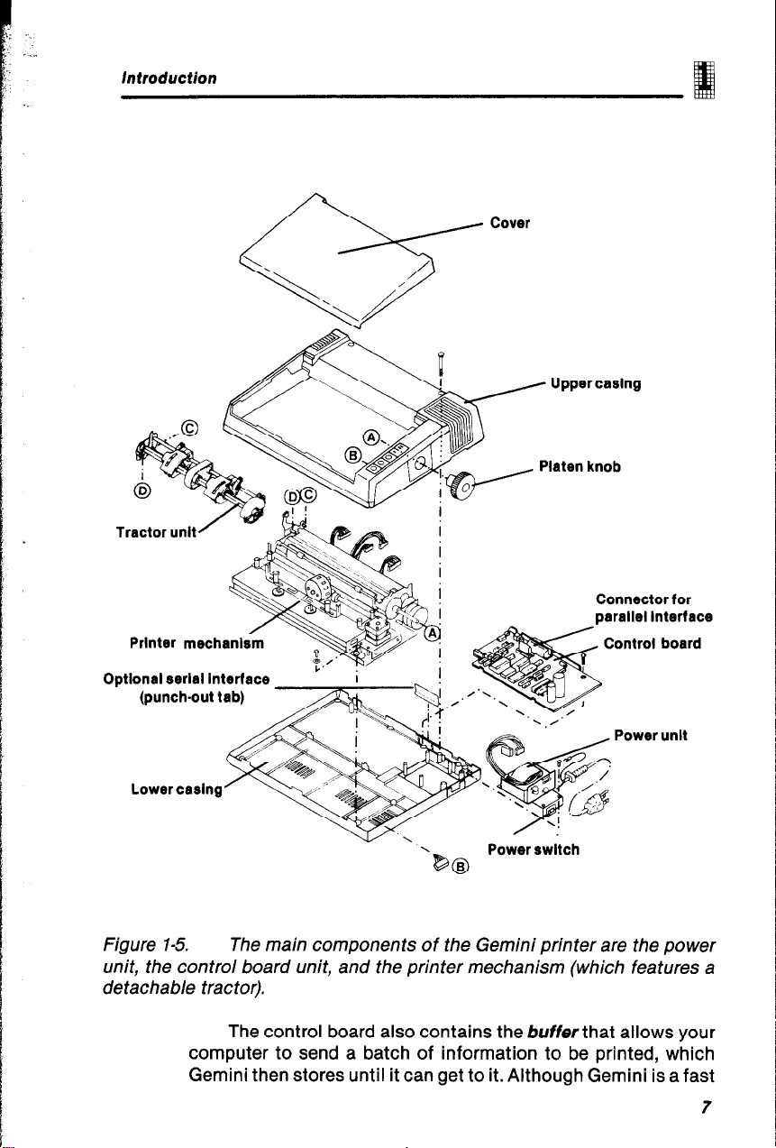
Figure l-5. The main components of the Gemini printer are the power
unit, the control board unit, and the printer mechanism (which features a
detachable tractor).
The control board also contains the buffer that allows your
computer to send a batch of information to be printed, which
Gemini then stores until it can get to it. Although Gemini is a fast
7
Page 14
Gemini User’s Manual
printer, computers communicate data even faster. The buffer can
accommodate 816 characters of memory, with an optional buffer
that can be expanded to 4K or 8K. Qu’est-ce que “K”?
Computer memory is measured in terms of K, meaning
ki/o&fes. A kilobyte is 1,024 bytes, and a byfe equals one letter
of the alphabet (or a symbol, or a number).
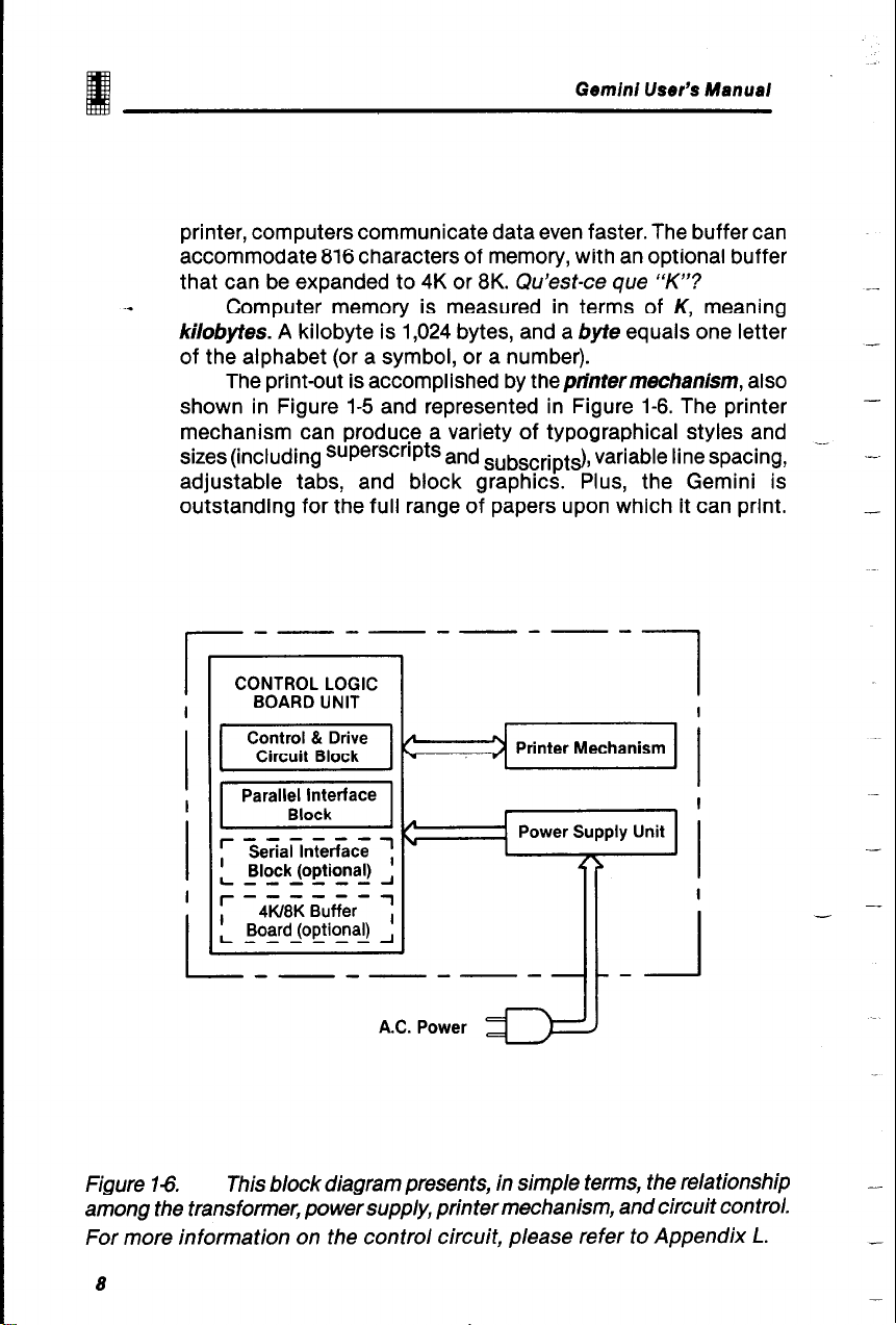
The print-out is accomplished by theprintermechanism, also
shown in Figure l-5 and represented in Figure 1-6. The printer
mechanism can produce a variety of typographical styles and
sizes (including superscripts and
adjustable tabs, and block graphics. Plus, the Gemini is
outstanding for the full range of papers upon which it can print.
subscripts), variable line spacing,
__
-
I
I -
Figure 143. This block diagram presents, in simple terms, the relationship
among the transformer, power supply, printer mechanism, and circuit control.
For more information on the control circuit, please refer to Appendix L.
_--------
CONTROL LOGIC
BOARD UNIT
1 I
I
A.C. Power
I
I
I
_
8
Page 15

introduction
GEMINI’S OPERATING ENVIRONMENT
When you install your Gemini printer, you should use common
sense and good judgment about where you place it. The following
are worthy of consideration in evaluating a potential operating
environment:
Position Gemini horizontally on a level surface.
Pick a place that does not have
extremes in temperature
(very hot or very cold)
strong vibrations
dusty atmosphere
oil present
metal particles nearby.
Avoid placing Gemini where it will be exposed to
direct sunlight, or close to a heater or heatgenerating applicances.
Provide a separate power supply, away from
noise-generating motors.
The power supply must not be more than 10%
more or less than 120 volts A.C., 220 volts
A.C., or 240 volts A.C. (as specified on the
product identification plate). Note: Extremely
high or low voltage will cause printer printer
problems.
The Gemini printers are valuable information-handling tools.
These tips will help you pick a good setting for the Gemini. Chapter
10 provides maintenance suggestions for keeping your printer in
good working order.
9
Page 16
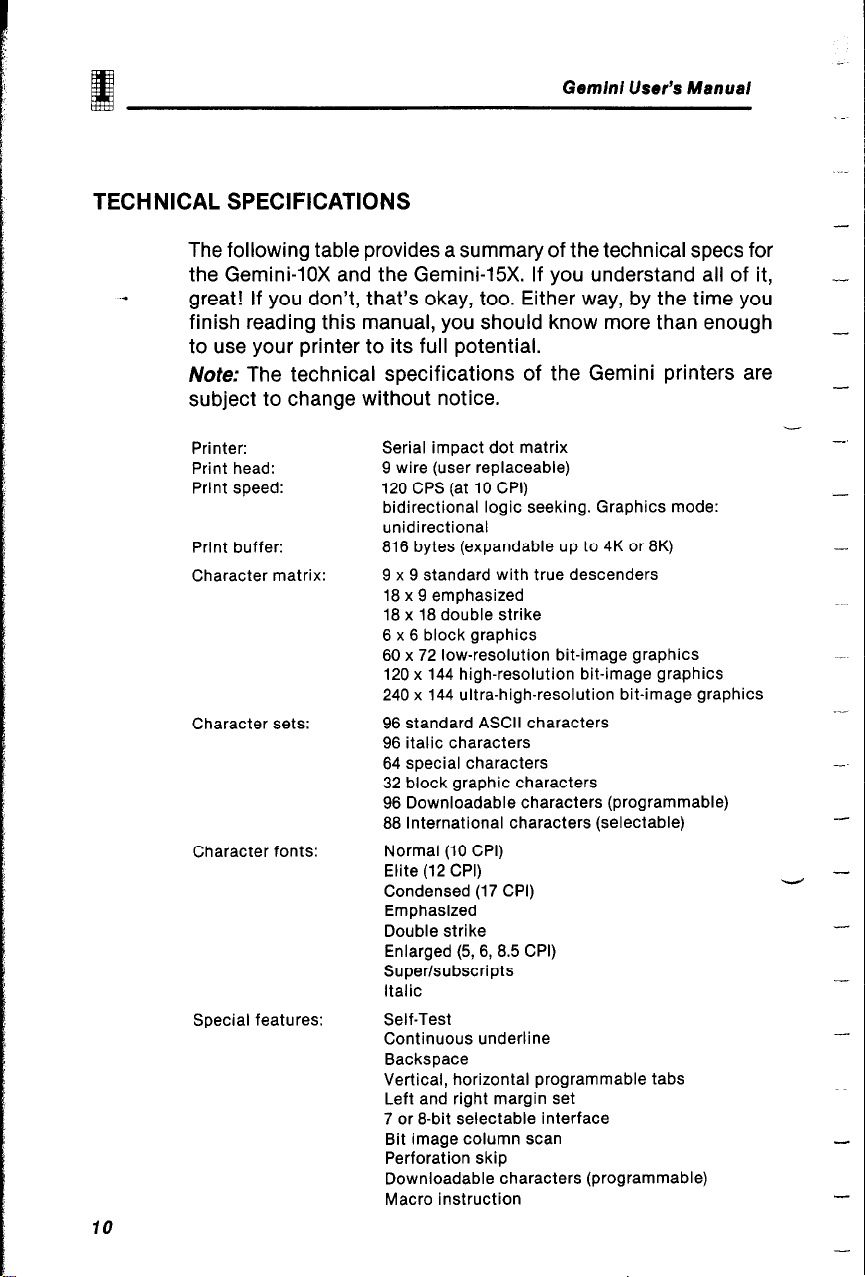
TECHNICAL SPECIFICATIONS
The following table provides a summary of the technical specs for
the Gemini-lox and the Gemini-15X. If you understand all of it,
.*
great! If you don’t, that’s okay, too. Either way, by the time you
finish reading this manual, you should know more than enough
to use your printer to its full potential.
Note: The technical specifications of the Gemini printers are
subject to change without notice.
Gemini User’s Manual
10
Printer:
Print head:
Print speed:
Print buffer:
Character matrix:
Character sets:
Character fonts:
Special features:
Serial impact dot matrix
9 wire (user replaceable)
120 CPS (at 10 CPI)
bidirectional logic seeking. Graphics mode:
unidirectional
816 bytes (expandable up to 4K or 8K)
9 x 9 standard with true descenders
18 x 9 emphasized
18 x 18 double strike
6 x 6 block graphics
60 x 72 low-resolution bit-image graphics
120 x 144 high-resolution bit-image graphics
240 x 144 ultra-high-resolution bit-image graphics
96 standard ASCII characters
96 italic characters
64 special characters
32 block graphic characters
96 Downloadable characters (programmable)
88 International characters (selectable)
Normal (10 CPI)
Elite (12 CPI)
Condensed (17 CPI)
Emphasized
Double strike
Enlarged (5, 6, 8.5 CPI)
Super/subscripts
Italic
Self-Test
Continuous underline
Backspace
Vertical, horizontal programmable tabs
Left and right margin set
7 or 8-bit selectable interface
Bit image column scan
Perforation skip
Downloadable characters (programmable)
Macro instruction
-.
-
-
‘rl -
-
-
-
-
Page 17
introduction
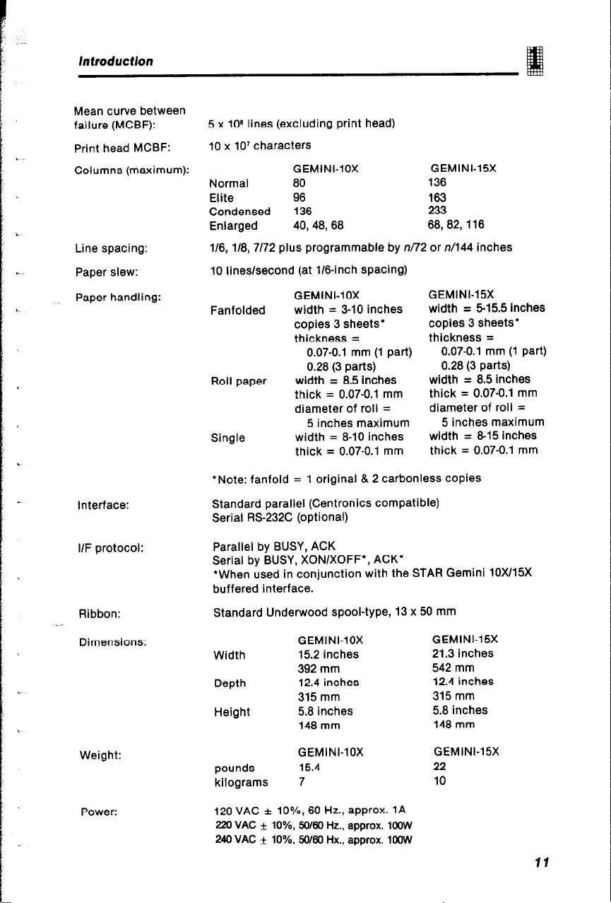
Mean curve between
failure (MCBF):
Print head MCBF:
Columns (maximum):
Line spacing:
Paper slew:
Paper handling:
Interface:
5 x lo8 lines (excluding print head)
10 x 10’ characters
GEMINI-10X GEMINI-15X
Normal 80 136
Elite
Condensed 136
Enlarged 40, 48,68 68,82,116
l/6, l/8, 7/72 plus programmable by n/72 or n/144 inches
10 lines/second (at l/s-inch spacing)
Fanfolded
Roll paper
Single
*Note: fanfold = 1 original & 2 carbonless copies
Standard parallel (Centronics compatible)
Serial RS-232C (optional)
96
GEMINI-10X
width = 3-10 inches
copies 3 sheets’
thickness =
0.07-0.1 mm (1 part)
0.28 (3 parts)
width = 8.5 inches
thick = 0.07-0.1 mm
diameter of roll =
5 inches maximum
width = 8-10 inches
thick = 0.07-0.1 mm
163
233
GEMINI-15X
width =
copies 3 sheets”
thickness =
width =
thick = 0.07-0.1 mm
diameter of roll =
width =
thick = 0.07-0.1 mm
5-15.5 inches
0.07-0.1 mm (1 part)
0.28 (3 parts)
8.5 inches
5 inches maximum
8-15 inches
I/F protocol:
Ribbon:
Dimensions:
Weight:
Power:
Parallel by BUSY, ACK
Serial by BUSY, XONIXOFF’, ACK’
‘When used in conjunction with the STAR Gemini 10X/15X
buffered interface.
Standard Underwood spool-type, 13 x 50 mm
GEMINI-10X
Width
Depth
Height
pounds
kilograms 7
120 VAC f lo%, 60 Hz., approx. 1A
220 VAC f lo%, 50/66 Hz., approx. 1oOW
240 VAC f lo%, 5J/60 Hx., approx. 1OOVV
15.2 inches
392 mm
12.4 inches
315 mm
5.8 inches
148 mm
GEMINI-10X GEMINI-15X
15.4
GEMINI-15X
21.3 inches
542 mm
12.4 inches
315 mm
5.8 inches
148 mm
22
10
11
Page 18
--
-
-.
-
--
--
-
-
-
Page 19
PAPER AND RIBBON
With Chapter 1 now “imprinted” in your memory, you’re almost
ready to apply all these new discoveries about the Gemini printer.
In this chapter, we’ll learn how to load paper into the printer, install
the ribbon, and set the print head gap. Chapter 3 will give you a
chance to print something; to see the results of what you’ve
learned so far. But first, let’s explore the options for loading
different types of paper.
If you’ve borrowed a Gemini printer (until getting your own),
you should refer to Appendix G to learn how to attach the various
paper-feed accessories. Appendix G tells you what the new owner
gets when first opening the box and how all the pieces fit together.
This chapter assumes you know “how” the pieces fit together, and
you only need to learn “why:’
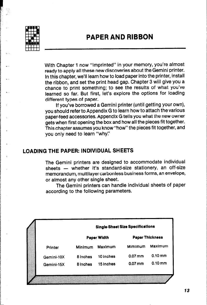
LOADING THE PAPER: INDIVIDUAL SHEETS
The Gemini printers are designed to accommodate individual
sheets -
memorandum, multilayer carbonless business forms, an envelope,
or almost any other single sheet.
The Gemini printers can handle individual sheets of paper
according to the following parameters.
whether it’s standard-size stationery, an off-size
Prlnter
Gemini-lox
Gemlnb15X
SlngbShret Size Speclflcatlons
Paper Wldth
Minimum Maximum
8 inches
8 Inches
10 inches
15 Inches
Paper Thickness
Mlmimum Maximum
0.07 mm
0.07 mm
0.10 mm
0.10 mm
13
Page 20
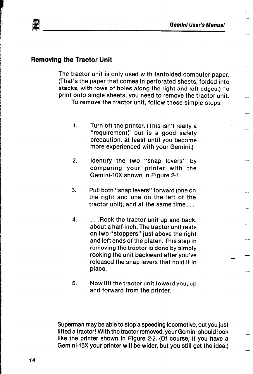
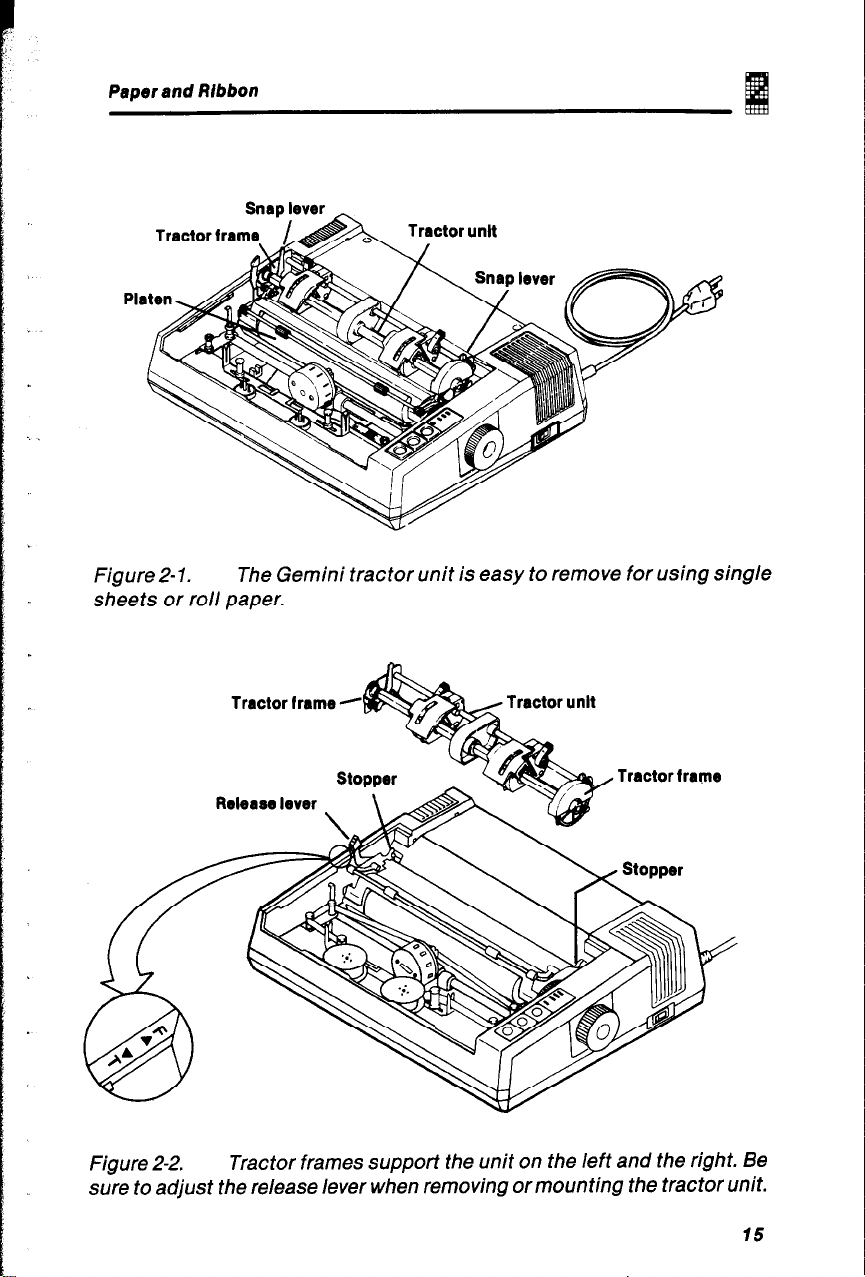
Removing the Tractor Unit
The tractor unit is only used with fanfolded computer paper.
(That’s the paper that comes in perforated sheets, folded into
stacks, with rows of holes along the right and left edges.) To
print onto single sheets, you need to remove the tractor unit.
To remove the tractor unit, follow these simple steps:
1.
Turn off the printer. (This isn’t really a
“requirement:’ but is a good safety
precaution, at least until you become
more experienced with your Gemini.)
-
Gemini User’s Manual
--
_
-
-
2.
Identify the two “snap levers” by
comparing your printer with the
Gemini-lox shown in Figure 2-1.
3.
Pull both “snap levers” forward (one on
the right and one on the left of the
tractor unit), and at the same time. . .
4.
. . .
Rock the tractor unit up and back,
about a half-inch. The tractor unit rests
on two “stoppers” just above the right
and left ends of the platen. This step in
removing the tractor is done by simply
rocking the unit backward after you’ve
released the snap levers that hold it in
place.
5.
Now lift the tractor unit toward you, up
and forward from the printer.
Superman may be able to stop a speeding locomotive, but you just
lifted a tractor! With the tractor removed, your Gemini should look
like the printer shown in Figure 2-2. (Of course, if you have a
Gemini-15X your printer will be wider, but you still get the idea.)
-
.-
-_
-
-
_
-
14
Page 21
Paper and Ribbon
FigureZ-1.
The Gemini tractor unit is easy to remove for using single
sheets or roll paper.
Tractor frame -
Release lever
Figure 2-2.
Tractor frames support the unit on the left and the right. Be
sure to adjust the release lever when removing or mounting the tractor unit.
15
Page 22
Gem/n/ User’s Manual
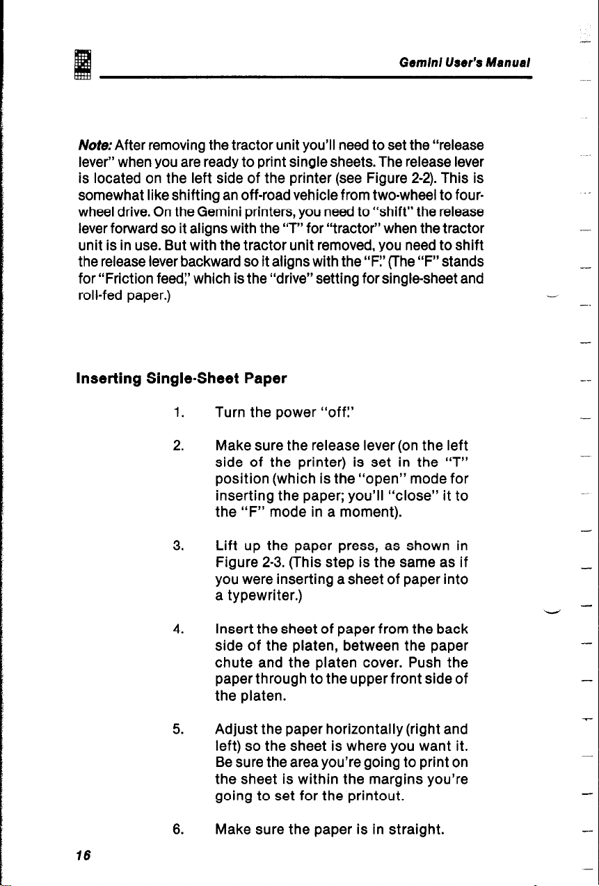
Note:After removing the tractor unit you’ll need to set the “release
lever” when you are ready to print single sheets. The release lever
is located on the left side of the printer (see Figure 2-2). This is
somewhat like shifting an off-road vehicle from two-wheel to fourwheel drive. On the Gemini printers, you need to “shift” the release
lever forward so it aligns with the ‘7” for “tractor” when the tractor
unit is in use. But with the tractor unit removed, you need to shift
the release lever backward so it aligns with the ‘IF!’ (The “F” stands
for “Friction feed:’ which is the “drive” setting for single-sheet and
roll-fed paper.)
Inserting Single-Sheet Paper
1.
Turn the power “off:’
.4
-
-
-.
-
2.
3.
4.
5.
6.
Make sure the release lever (on the left
side of the printer) is set in the “T”
position (which is the “open” mode for
inserting the paper; you’ll “close” it to
the “F” mode in a moment).
Lift up the paper press, as shown in
Figure 2-3. (This step is the same as if
you were inserting a sheet of paper into
a typewriter.)
Insert the sheet of paper from the back
side of the platen, between the paper
chute and the platen cover. Push the
paper through to the upper front side of
the platen.
Adjust the paper horizontally (right and
left) so the sheet is where you want it.
Be sure the area you’re going to print on
the sheet is within the margins you’re
going to set for the printout.
Make sure the paper is in straight.
--
-
-
-
-
-
15
-
Page 23

I
_.
.‘:
: “.
Paper and Ribbon
7.
.Position the sheet of paper where you
want the first line of text to start
printing. (It may take you a little practice
to get the placement consistently right,
but you’ll master it quickly.)
6.
Push the release lever back to the
“closed” position, indicated by “F1’
9.
Return the paper press to the original
position, flush against the paper.
10.
Replace the cover and turn the power
“on?
Note: Never touch the printing head during printing. Aside from
the mechanical injury threat associated with touching a fastmoving device, there is the danger of burning your fingers. As
the caution label on the print head states:
Caution: Hot Surface, Avoid Contact
Release lever
Paper
I -KC$Bk
Single sheet paper
, Paper chute
Figure 2-3.
Inserting a single sheet of paper into the Gemini-15X
(shown here) and the Gemini-lOXis just as easy as rolling a sheet ofpaper
into a standard typewriter.
17
Page 24
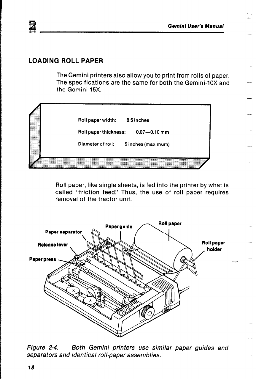
LOADING ROLL PAPER
The Gemini printers also allow you to print from rolls of paper.
The specifications are the same for both the Gemini-lox and
the Gemini-15X.
,.:
2: .:
:
. . . . .’
. .
: : . .
..)
,.
‘:jY y
:..
> ” ‘.
‘.
.: ,, :
.,
::: .,
Roll paper width:
Roll paper thickness: 0.07-0.10 mm
Diameter of roll: 5 Inches (maximum)
Roll paper, like single sheets, is fed into the printer by what is
called “friction feed? Thus, the use of roll paper requires
removal of the tractor unit.
Gemini User’s Manuai
8.5 inches
Paper separator
Figure 2-4.
Both Gemini printers use similar paper guides and
separators and iden tical roll-paper assemblies.
18
-
Page 25
Paper and Ribbon
Roll paper utilizes the metal racks, which come as
accessories with every Gemini printer. As shown in Figure 2-4,
these accessories include the paper guide, paper separator,
roll-paper holder, and holder shaft. For information on how to
attach these accessories, please refer to Appendix G.
The steps for inserting roll paper are fairly simple and
straightforward:
1. Turn the power “off:’
2.
Remove the tractor unit, if you haven’t
already done so.
3.
Following the procedures described in
Appendix G,
attach the paper
separator, guide, and holder.
4.
Pull the release lever (located on the left
side of the top-front part of the printer)
into the “open” position. As with singlesheet paper, the “open” position is
indicated by the letter “TV
5.
Lift the paper press.
6. Pull the paper separator upright, as
depicted in Figure 2-4 (for the
Gemini-lox). The paper guide should
remain horizontal.
7.
Load the paper roll, as shown in Figure
2-4, so that when viewed from the
printer’s right side, the paper will unroll
in a clockwise direction.
8. As shown in Figure 2-5 (for the
Gemini-15X), unroll some paper and
pass it above the paper guide and
underneath the up-ended paper
separator.
19
Page 26
paper separator
Gemini User’s Manual
guide
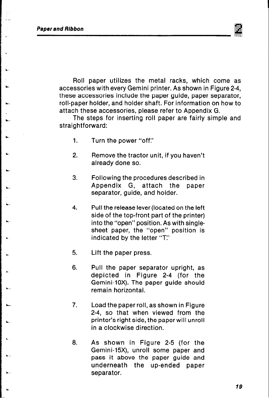
Figure 2-5.
inserting roll paper in the Gemini printer is similar to
inserting sing/e sheets, with accessories to accommodate the fact that
the “sing/e-sheet” in this case is quite long.
9.
Insert the roll paper into the paper
chute, then push the paper through so
it goes around the platen.
When the paper has been pushed
10.
through so it’s above the paper press,
push the press back so it’s in its
operational position (that is, flush
against the paper).
Adjust the paper, if necessary, so it will
11.
feed through straight; then push the
release lever back to the “locked” or
“closed” position, marked with the
letter “FI’
12.
Lower the paper separator, as shown in
Figure 2-6.
20
-
-
Page 27
Paper and Ribbon
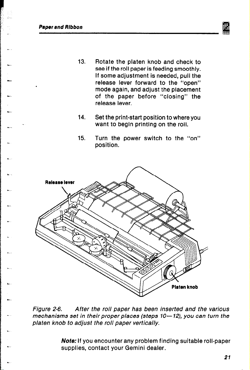
13. Rotate the platen knob and check to
see if the roll paper is feeding smoothly.
If some adjustment is needed, pull the
.
release lever forward to the “open”
mode again, and adjust the placement
c
of the paper before “closing” the
release lever.
14.
Set the print-start position to where you
want to begin printing on the roll.
15.
Turn the power switch to the “on”
position.
Figure 2-6.
After the roll paper has been inserted and the various
mechanisms set in their proper places (steps 70- 12), you can turn the
platen knob to adjust the roll paper vertically.
Note: If you encounter any problem finding suitable roll-paper
supplies, contact your Gemini dealer.
21
Page 28
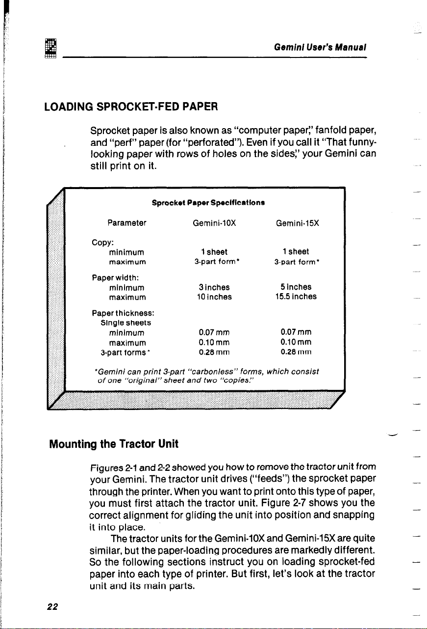
LOADING SPROCKET-FED PAPER
Sprocket paper is also known as “computer paper:’ fanfold paper,
and “perf” paper (for “perforated”). Even if you call it “That funnylooking paper with rows of holes on the sides:’ your Gemini can
still print on it.
Sprocket Paper Speclflcations
Parameter
Gemini-lox Gemini-15X
Gemini User’s Manual
-
copy:
minimum
maxlmum
Paper width:
minimum
maximum
Paper thickness:
Single sheets
minimum
maximum
3-part forms*
*Gemini can print 3-part “carbonless” forms, which consist
of one “original” sheet and two “copies.”
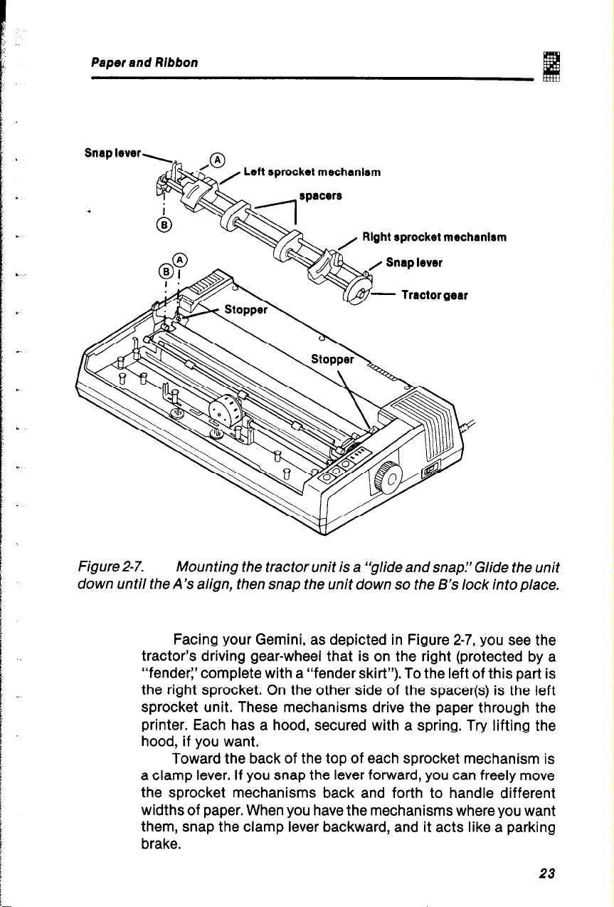
Mounting the Tractor Unit
Figures 2-1 and 2-2 showed you how to remove the tractor unit from
your Gemini. The tractor unit drives (“feeds”) the sprocket paper
through the printer. When you want to print onto this type of paper,
you must first attach the tractor unit. Figure 2-7 shows you the
correct alignment for gliding the unit into position and snapping
it into place.
The tractor units for the Gemini-lox and Gemini-15X are quite
similar, but the paper-loading procedures are markedly different.
So the following sections instruct you on loading sprocket-fed
paper into each type of printer. But first, let’s look at the tractor
unit and its main parts.
1 sheet
3-part form’
3 inches
10 inches
0.07 mm
0.10 mm
0.28 mm
1 sheet
-
3-part form’
5 inches
15.5 inches
0.07 mm
O.lOmm
0.28 mm
-
-
-
-
22
Page 29
Paper and Ribbon
Left sprocket mechanlrm
Right sprocket mechanism
E
t
j
L
Figure 2-7.
Mounting the tractor unit is a “glide and snap.” Glide the unit
down until the A’s align, then snap the unit down so the B’s lock into place.
Facing your Gemini, as depicted in Figure 2-7, you see the
tractor’s driving gear-wheel that is on the right (protected by a
“fender:’ complete with a “fender skirt”). To the left of this part is
the right sprocket. On the other side of the spacer(s) is the left
sprocket unit. These mechanisms drive the paper through the
printer. Each has a hood, secured with a spring. Try lifting the
hood, if you want.
Toward the back of the top of each sprocket mechanism is
a clamp lever. If you snap the lever forward, you can freely move
the sprocket mechanisms back and forth to handle different
widths of paper. When you have the mechanisms where you want
them, snap the clamp lever backward, and it acts like a parking
brake.
23
Page 30
Gemini-lox Loading Sprocket Paper
The Gemini-lox should be loaded with sprocket-fed paper
according to the following steps.
Turn the power switch “off?
1.
Gem/n/ User’s Manual
2.
3.
4.
5.
6.
7.
8.
9.
10.
Install the tractor unit.
Install the paper separator and paper
guide, as described in Appendix G.
Pull the release lever, located on the left
side of the printer, toward the “open”
position (marked ‘IT”).
Lift up the paper press.
Pull the paper separator upright, as shown
in Figure 2-8.
Place the stack of fanfolded computer
paper behind the printer.
Pick up the top sheet of paper and feed it
between the paper chute and the platen
cover, from the back side of the platen.
Push the paper down and forward, so it
wraps around the platen.
Return the paper separator to its original
position,
-
11.
Open the tractor covers atop the right- and
left-sprocket mechanisms, as shown in
Figure 2-9.
Pull the paper up, past the sprocket
12.
mechanisms.
24
Page 31

Paper and Ribbon
Figure 243.
Feed the paper around the p/a ten (“roller’l) of the Gemini- 10X,
then push the paper separator “downrightY(That’s the opposite of “upright”
-
not to be confused with “downwrongl’)
13.
Flip the clamp levers forward on the
sprocket mechanisms; adjust each
mechanism (right and left) so that the
sprockets (the nubby little “teeth”
protruding from the sprocket wheel) align
with the holes on the paper.
14.
Adjust the sprockets so they are lined up
with the sprocket holes.
15.
Close the tractor covers and snap the
clamp levers back into the “locked”
position. (See Figure 2-10.)
16.
Rotate the platen knob, and roll the paper
up or down until the correct “print-start”
position is obtained.
17.
When the paper installation is completed,
replace the printer cover and turn the power
on.
Page 32

Tractor cover
Gemini User’s Manual
Clamp lever
Figure 2-9.
Expose the “teeth” of the sprockets, and align the
mechanisms so the paper “feeds” through them.
Figure 2- 70.
If the sprocket paper you just loaded in your Gemini-lox is
multilayer (non-carbon) forms, then refer to the end of this chapter to learn
how to adjust the print-gap.
26
Page 33

Paper and Ribbon
Gemini-l 5X Loading Sprocket Paper
The Gemini-15X can be loaded with sprocket paper exactly the
*
same as can the Gemini-lox, but with one important difference.
The Gemini-15X is designed to accept paper either from the back
of the printer or paper fed from beneath the printer. That’s right,
there’s a slot in the undercarriage that lets you position the
Gemini-15X above your stack of fanfold computer paper; this paper
is fed up through the printer and out the back.
Following are the steps for loading sprocket paper to and
through the Gemini-15X. Figure 2-11 illustrates steps 1 through 6.
Turn the power “off?
1.
2.
3.
4.
5.
6.
7.
8.
Install the tractor unit, as illustrated in
Figure 2-7 (on page 23).
Attach the paper separator and paper
guide (they are the two metal racks that are
described in Appendix G).
Pull the release lever, located on the left
side of the printer, toward the “open”
position (marked “T”).
Raise the paper press.
Lift up the paper separator.
Raise the tractor covers on the sprocket
mechanisms (as shown in Figure 2-12).
Snap the clamp levers (atop the sprocket
mechanisms) forward to the open position,
and move the sprocket mechanisms away
from each other until there is enough room
between them to accommodate the paper.
27
Page 34

Paper separator,
Gemini User’s Manual
Figure 2-l 1.
The first step is to prepare the Gemini-75X by putting the
mechanical controls in the “open”position.
Stepsg-12leadyoudown twoseparatepaths:Steps9A through
12A are for loading sprocket paper from “behind” the printer; steps
9B through 12B instruct you on loading paper from “beneath” the
Gemini-15X.
9A.
Place the stack of fanfolded computer
paper behind the printer.
10A. Insert the sprocket paper from the back of
the printer (as shown in Figure 2-12).
11A. Feed the top sheet between the paper
chute and the platen cover, and around the
platen to the front.
12A. Push the paper up past the paper press,
and return the paper separator to its
horizontal position.
26
-
Page 35

Paper and Ribbon
The other option is to:
98.
.
1OB. Pick up the first sheet of the perforated
11B. Push the paper up toward the front of the
12B. Feed the top sheet inside the paper press
Place the sprocket paper below the printer
(ideally, on the second shelf of a specialpurpose printer table, with the printer
above it on a shelf with a built-in slot).
stack of fanfolded pages, and lift it up and
through the slot in the undercarriage of the
Gemini-15X.
platen.
and past the platen, far enough up so you
can grip the paper from above the printer.
Figure 2- 12.
The Gemini-15X can be loaded with sprocket paper from the
back (as shown here) or from a stack of paper beneath the printer (depicted
in Figure Z-13).
29
Page 36

Gem/n/ User’s Manual
-
“Back Pass”
Figure 2-13.
A
.
.
“Bottom Pass” :
.
.
loadlng :
Whether you use the “bottom pass” (shown here) or the
“back pass” option (also shown), you start and end with the same steps.
30
13. Adjust the paper so that it will feed through
straight, and push the paper press back to
its operational position.
14.
Horizontally adjust the sprocket
mechanisms right or left so they align with
the sprocket holes on the paper.
15.
Vertically turn the sprocket “teeth” (the
little nubs on the sprocket wheels) so they
line up with the holes on the paper.
16. Snap the clamp levers back into the
“closed” position.
Page 37

Paper and Ribbon
17. Close the tractor covers.
.
start position of the paper.
19. Turn the power “on” and put your Gemini
to work for you.
NoWThe best “start-position” (step 18) will vary according to the
paper on which you are printing and the number of blank lines in
your document. If you are a novice with dot matrix printers, you
might try to position your paper just above the in-place paper press
for your first attempts. With practice, you’ll be able to place the
paper right where you want to start printing.
18. Rotate the platen knob, and set the print-
Another note: If you use multipart paper (such as a three-sheet
carbonless form) with your Gemini-15X, you’ll need to adjust the
print gap, as discussed later in this chapter.
Congratulations! You’ve learned how to load the paper.
Next, we’ll discuss the ribbon and print gap,
then you’ll be on your way to less reading and more printing.
Page 38

LOADING THE RIBBON
You already know that your Gemini printer is one of the best buys
.
available today in terms of what you get for your initial investment.
What’s more, Gemini’s sensible ribbon requirements are even
more economical as time passes.
That’s because Gemini uses ordinary typewriter ribbons on
spools. When the ribbon has gone from one spool to the other,
Gemini automatically reverses the ribbon direction.
After the ribbon starts wearing out (when your printed
material starts getting too light), you can invert the ribbon and start
over.
Replacing the ribbon (which you’ll have to do eventually) is
easy and inexpensive.
Geminl User’s Manual
32
Ink Ribbon Speclficatlons
Ribbon Color
Material
Dimensions
width:
length:
Spool Standard
Recommended Product
black
nylon (#40)
112 inch (13 mm)
11.5 yards (10.5 m)
Underwood’s plastic type
(13 x 50 mm diameter)
Type SF-OSB made by
Fuji Kagakushi Kogyo
Near each end of the ribbon, there is a metal or plastic eyelet that
signals Gemini to reverse the ribbon direction. It will do this
automatically. When loading the ribbon, you should be careful to
place the eyelet properly in the ribbon’s threading configuration.
--
-
Page 39

Paper and Rlbbon
How to Set the Ribbon
Telling you how to set the ribbon is like writing a narrative
*
describing how to tie your shoelaces. Figure 2-14 and 2-15 show
you the way to thread the ribbon on the Gemini-lox and
Gemini-15X, respectively. But before you try it, you would do well
to review the hints provided here.
Hint PI:
Hint #2:
.
Figure 2-14.
Turn the power “off:’
Slide the print head gently with your fingers
to the approximate center of its pathway
(Figures 2-14 and 2-15).
The ink ribbon pass for the Gemini-lox.
p _.-.__-.-. -.--77
Ribbon guide
A4
.-._
Cl
r/ Ribbon guide
.-.-._.
-.-.-.- .-._._. ~
0.
b&Yp.a-
Figure 2- 15.
The ink ribbon pass for the Gemini-75X.
*+
Ribbon spool
33
Page 40

Gemini User’s Manual
Hint #3:
Begin by setting either ribbon spool
securely on a ribbon spool axle. Make sure
you have the spool positioned so it will
wind/unwind as shown in the figures. Place
the spool securely on the axle, so that the
“drive pins” engage the spool.
-
Figure 2-16.
You might want to use a ball point pen to lightly press
the ribbon guide toward the platen while inserting the ribbon.
Hint ++4:
Then thread the ribbon, taking care around
the print head. Figure 2-16 shows how to
insert the ribbon in the slot between the
print head and the ribbon guide. Figure
2-17 shows you how to position the ribbon
to avoid misprints or to prevent the ribbon
coming off during printing.
34
-
-
-,
Page 41

Paper and Ribbon
ink ribbon
(incorrect)
Figure 2- 17.
Print head
(incorrect)
Two wrongs don’t make a right, so try to be careful
Ribbon guide
(Correct)
when setting the ribbon near the print head (shown here).
Release lever
Eyelet grommet
Ribbon spool
Figure 2- 18.
The eyelet grommet (which signals Gemini to
automatically reverse the ribbon direction) is shown correctly placed on
the ribbon-spool side of the changeover lever.
35
Page 42

Gemini User’s Manual
Hint #5:
The eyelet grommet (which signals Gemini
to automatically reverse the ribbon
direction) should be placed on the ribbon-
d
Hint #6:
spool side of the changeover lever.
Set the other ribbon spool on the opposite
--
-,
spool axle, making sure the “drive pins” are
Hint #7:
engaged.
When the ribbon threading has been
-
--
accomplished, turn the ink ribbon spools
by hand, approximately four or five
rotations of the spools. This verifies that
everything was done properly and that the
ribbon is smoothly fed.
Hint #8:
As shown in Figure 2-19, you can turn the
ribbon over and use the other side when it
starts wearing out.
Used up
Figure 2-19.
Turning the ribbon over gives you the same effect as
having a new ribbon but at no extra cost.
36
-
Page 43

Paper and Ribbon
1
i
ADJUSTING THE GAP BETWEEN
THE PRINT HEAD AND PLATEN
Gemini printers can accommodate papers of varying thicknesses
.
by allowing you to change the print-head gap. This “gap” is the
distance between the print head and the platen.
Gap adjustment is done by moving the “adjust lever:’ which
is immediately in front of the “release lever” (see Figure 2-18).
Pulling the “adjust lever” forward will widen the gap, and pushing
it backward will make the print-head gap narrower.
There are five positions that can be attained by moving the
lever to different adjustments. These five positions can be
changed by the control arm rest in different notches, as shown
in Figure 2-20. The “second position” is most commonly used for
single sheets of paper.
Figure Z-20.
/ever allow you to print on paper ranging from 0.07 mm (that’s thin) to
0.28 mm (for three-layer carbonless forms).
The different positions of the print-head gap-adjustment
If you are unsure of which is exactly the right print-head gap
adjustment to make, experiment. In time, you’ll get the best
results.
With the turn of a page, you’ll be ready to check your work,
as Chapter 3 introduces you to Gemini’s Self-Test.
37
Page 44

-
--
_& - -M-u,“‘=
._s. M.
- --------
-
-
Page 45

L
L..
II.
GEMINI SELF=TEST
“Self-Test” is the name of the built-in program that prints out
several sample lines of letters, numbers, and other characters to
show you that everything is in good working order. You can print
the Self-Test without hooking up your Gemini to a computer.
The Gemini Self-Test is a special feature that allows you to
check your installation of the paper and ribbon and the adjustment
of the print head gap. At the same time, the printout provides a
preview of what’s to come: all the standard characters in both
normal and italic type styles.
HOW TO INITIATE THE SELF-TEST
The Gemini Self-Test is as easy as “one, two, three?
t
3. While holding down the “LF” button on the
The Self-Test (shown on the following two pages) will print out
automatically. If you hold down the “LF” button, the Self-Test will
continue printing out.
The Gemini-lox Self-Test (Figure 3-1, a &. b) consists of four
lines that show the standard character set that your printer can
produce. The Gemini-15X Self-Test (Figure 3-2, a & b) uses the
same characters, and is also displayed on four lines.
Chapter 4 if you are in a hurry to hook-up your Gemini to your
computer and start printing out data that you generated. On the
other hand, if you want to take a few minutes to finish this chapter,
you’ll learn what these characters represent and how to use them.
Plug the printer’s electrical plug into an
1.
electrical outlet.
2. Insert a sheet of paper.
control panel, turn the power switch “on?
After you run the Self-Test on your printer, you can skip to
39
Page 46

WHAT THE SELF-TEST LOOKS LIKE
Gemini User’s Manual
I
I
Figure 3-la.
actual size).
.-
The left side of the Gemini-lox Self-Test printout (shown
-
Figure 3-2a.
actual size).
40
The left side of the Gemini-15X Self-Test printout (shown
-
-
Page 47

Self- Test
I
I
GHIJ~::LMNOF’QHSTlJVWXY%C\l.“‘_ ‘abc:defghi _il:lmno , 0
I
I
Figure 3- 1 b.
The right side of the Gemini-lox Self-Test, which is a
continuation of this two-part figure.
Figure 32b.
The right side of the Gemini-15X Self-Test, which is a
continuation of this two-part figure.
41
Page 48

Gemini User’s Manual
WHAT THE SELF-TEST MEANS
The Gemini Self-Test allows you to test the printer’s performance
before putting it to work. Beyond that, the Self-Test is a
demonstration of some of the characters Gemini has stored in
its permanent memory.
On the following pages, groups of characters from the Self-
Test are identified and discussed. Where a character has multiple
meanings or uses, this manual provides the most common and
generally used.
In discussing these characters, we face the old problem of
defining a word without using that word in the definition. To make
it easier to identify which character we’re discussing, we’ve coded
some of the characters to correspond with letters of the English
alphabet. If you look at Figure 3-3, you’ll see that the fifth character
shown in the sequence on the lower line is the “percent” sign. For
purposes of our discussion, we’ve coded it so it corresponds to
the letter “f” above it. In Chapter Five, you’ll learn about other
“codes” that have been created to facilitate discussion about
computer-generated characters.
-
-
-
-
-
-
-
_
-
abcdefghijklmnop
,T!
rstuvwx
!“#B%&’ Ot+,-./012345678Y:~(->?B
Figure 3-3.
The first part (of the first Self-Test lines) shows the
characters often associated with the top row of keys on a typewriter.
42
--
- -
-
-
-
-
-
-
Page 49

Se/f-Test
In Figure 3-3, the letter “a” codes a character that’s as hard
to see as the wind. That’s because the first line begins with a
blank space.
The “blank” character may not seem important, but without
it:
everythingwouldruntogetherlikethis
The first character that appears in the lower line of Figure 3-3
is the “exclamation point” (coded “b”). This is also called the
“factorial” sign in mathematical symbolism.
The next eight characters (represented by “c” through “j”) are,
respectively: double quotation marks, the “number” sign (if it
precedes a numeral: as in #!5; or a “pound” sign if it follows: as
in W), the dollar sign, the percent sign, the ampersand (also called
the “and” sign), the apostrophe (which also serves as the “final
single quotation mark), and the opening and closing parentheses.
The next six characters in Figure 3-3 (represented by letters
“k” through “pi’ respectively) are: the asterisk(or star), the “plus”
sign, a comma, the “minus” sign (which also serves as both the
hyphen and the short dash), a period, and the “slash” mark. The
“slash” (represented by letter “p” is also called the “diagonal:’
“slant:’ “solidus:’ and “virgule”; in the English money system, it
represents “shillings?
Letter “q” in Figure 3-3 represents the 10 characters for the
numerals “zero” through “nine:’ It might help to note the difference
between a “number” and a “numeral” at this time. A “byte” can
represent a character (such as the letter “m” or the numeral ‘?I”),
or a whole number. A “number” is a concept, and a “numeral” is
a character or group of characters that represent the concept.
In Figure 3-3, the letters “r” and “s” stand for the “colon” and
“semicolon” characters. The next three symbols are mathematical
signs that show the relationships of values. “cl’ means “is less
than”(such as “3~4”); “=I’ is the “equals” sign (and the “doublebond” sign in chemistry); and I‘>” means “is greater than” (such
as “6>4”). Next comes the “question” mark, and finally the “at”
sign. In everyday usage, “@” may be used like this: “4 diskettes
@ $5 = $20.” In some software packages, such as VisiCalc, the “at”
sign is part of a powerful command sequence.
Figure 3-4 presents the second part of the first line in the
Gemini Self-Test. The first 26 characters are the English alphabet’s
capital letters. These are also called the “upper case” letters.
43
Page 50

Gemini User’s Manual
-_
a bcdef
ARCDEFGHIJKLMNGPQRSTlJVWXYZC\l’.~-’
Figure 3-4.
The Self-Test prints the uppercase alphabet in the first
line, 10 characters per inch. In Chapter 5, you’ll learn how to print larger
and smaller letters (from 5 to 17 characters per inch).
In Figure 3-4, the characters coded “a” and “c” are “brackets:’
These are sometimes used in the same manner as parentheses.
The character coded “b” is a “reverse slash” - the mirror-image
of the “slash” in Figure 3-3. The next character, “ * :’ is a compute
symbol for depressing the “control key” on your keyboard. It canalso be used for a circumflex or exponentiation. Completing this
set of characters, the character coded “e” is the “underlining” for
a single character, and “f” represents the “opening single
quotation” mark.
In Figure 35, the “lowercase” equivalents of the “uppercase”
letters in Figure 3-4 are presented. These letters are also 10
characters per inch (CPI) in the Self-Test. Following the lowercase
letters in this figure are four characters coded “a” through “dl’ The
first and third are “braces:’ which provide an alternative to
parentheses and brackets, especially in grouping mathematical
terms. The symbol coded “b” is a special scientific symbol, to
which you may assign meaning according to its use. Finally, the
character marked “d” is the tilde sign or diacritical mark.
-
--
-
-
-
_-
_
-
-
.~
-
-
-
44
Page 51

Self-Test
abed
abc:def ghi iklmnopqrstuvwxyz.~ : 1”
Figure 3-5.
This segment of the Gemini Se/f-Test shows you what the
lowercase letters look like, unless you command the printer to use
another type sty/e or a different size.
Figure 3-6.
The 96 italic characters form the third line of the
Gemini-15X Self-Test: the third and fourth lines with the Gemini-lox.
These characters are the italic version of the characters
individually identified in Figures 3-3, 3-4, and 3-5.
TAKE A CLOSER LOOK
Now that you’ve considered the 96 “standard” characters and
the 96 italic characters, you’re ready to hook your Gemini up to
your computer and get started.
If you wonder what these characters would look like if viewed
up close, you might want to take a moment and turn to Appendix K.
45
Page 52

-
-
-
-
-
.._
-
/ / /\
-
_-
Page 53

INTERFACING GEMINI
WITH YOUR COMPUTER
Your Gemini printer is a remarkable example of modern
engineering. A few short years ago, the information-handling
capability built into Gemini would qualify the “printer” to be
considered a “computer” of sorts. When Gemini is interfaced
(“hooked up to”) your microcomputer, the results can be dazzling.
The characters identified in Chapter 3 are imbedded in
Gemini’s mad-on/ymemory(ROM’chips. Your computer doesn’t
need to tell Gemini how to print the set of dots that represents a
certain character; your computer just needs to tell Gemini which
ones and where.
When your computer identifies the characters selected for
printing, Gemini stores up to 816 bytes of data in its buffer at the
same time that it’s printing. Gemini even knows when it runs out
of paper -
signaling you of the problem.
Before we explore interfacing Gemini with your computer,
let’s briefly consider how Gemini’s control circuit is configured.
As graphically illustrated in Apendix L (control circuit block
diagram), Gemini features a central processing unit (CPU].
This CPU controls the electromechanical operations, such
as the print head, carriage motor and paper feed motor. This
CPU utilizes the random-access memory (RAM). It receives
data serially, or in parallel, depending on which type of
interface your system requires.
stopping the printing process and (if you wish)
41
Page 54

INTERFACE OPTIONS
Gemini provides a parallel interface as standard. Parallel interface
is common to almost all popular microcomputers currently on the
market. But some computers use serial processing transmission
and require serial interface capability. As shown in Figure 4-1,
Gemini is designed to accommodate either type of interface.
Gemini User’s Manual
-
-
-
--
Figure 4-1.
.
Parallel interface ,
(standard)
The Gemini printers are provided with the parallel interface
9
Control drive
b
circuit
CPU
ROM
RAM
I/O
as standard equipment, with a serial interface available as an option.
The parallel interface is incorporated in the same printed
circuitboard(PCB) as the contdcircuitboard. The optional serial
interface board is constructed to be attached directly to the PCB
and to fully reside within the body of the printer. If your system
requires a serial interface, contact your Gemini dealer for purchase
of the Gemini SBI-4010X serial interface board.
In the following section, we will discuss the parallel interface.
But first, let’s consider the DIP switches - where are they, what
are they, and what do they do? So turn your printer around, and
let’s look at the back.
-
-
-
-
-
-
-
-
-
-
48
Page 55

lnferfacing Gemini with Your Compufer
: L..
’
The DIP Switches
The dual-in-line package (DIP) switch is a device that controls the
printer’s “patterns of thought? Several functions can be selected
by appropriately setting the two DIP switches located on the
c
control logic board (Figure 4-2). DIP switch 2 can be set at the rear
of the printer as shown in Figure 4-3. It is necessary to remove the
upper casing to set DIP switch 1. Please refer to Chapter 10 for
instructions to remove the upper case. A status chart has been
provided on the back panel of this manual to assist you in
remembering the setting of each DIP switch in your printer.
Lr
Figure 4-2.
L
DIP switches on control logic board.
/Vote:Always set the DIP switches with the printer’s power turned
“Off?
Each pin in the DIP switch serves a distinct and separate
control function. The functions of DIP switch 1 are defined in
Figure 4-4. Figure 4-5 illustrates DIP switch settings for selection
of the various character sets. Figure 4-6 illustrates the settings
of DIP switch l-6,1-7, and 1-8 to choose international character
sets. Figure 4-7 contains the DIP switch 2 functions.
49
L.”
Page 56

Ground
Terminal
Gemini User’s Manual
\ DYS-4 /
DIP Switch 2
Connector for
Parallel Interface
Port Hole for Serial
Interface (optional)
Figure 4-3.
F
DIP switch 2 controls (1) detection of when your Gemini runs
Power Cord
out of paper, (2) the effect of the CR codes on buffer-full printing, (3) 7-bit or
8-bit interface, and (4) automatic line feed.
Dip
Switch
Pin No. Function
l-1
1-2
1-3
l-4
l-5
l-6
l-7
l-8
When
“On”
When
“Off”
Emphasized on
17 CPI
‘I, inch
Factory
Setting - -
on
on
on
on
on
on
on
Figure 4-4. The eight switch settings and functions for DIP switch 1. Note
that switch l-1 and 1-4, as well as l-6 through l-8 are explained in Figure
43 and 4-6 respectively.
-
-
-
-
50
Page 57

Interfacing Gemini with Your Computer
if DIP Switch 1-l
and l-4 are set as follows:
l-1
on on
on off
off
off off
l-4
on
Then, your Gemini
will print the following
character sets
Standard ASCII
Download
italic ASCII
italic ASCII
Figure 4-5. The setting of DIPswitches l-l and 14 control the charactersets.
DIP Switch Settings
l-6
on
off
on
off
on
off
on
off
l-7
on
on
off
off
on
on
off
off
l-6
on
on
on
on
off
off
off
off
Country
U.S.A.
England
Germany
Denmark
France
Sweden
Italy
Spain
Form Length
11 inches
11 inches
12 inches
12 inches
12 inches
12 inches
12 inches
12 inches
Figure 4-6. By setting different combinations of DIP switches l-6, 1-7, and
1-8, you can select different international character sets and the form
lengths that are standard in those countries.
51
Page 58

..::i
>>
;:&j$ Swlt ch
.: . . . . >>> ,.,.
i;i;i;:;:>;::::
ii... :.. :j.
‘ii)j;j:ii!i;
::::::::+:
::.~:.:::.::::,
:::j::j-;:y:
;:;;<i;:;;::::
:g;.;:;:;:x
. . . . . . . ,.>,.)
$piiiii~~
:‘i::‘::\,$:::
::‘.::‘,:>j:::
::::::::‘:::::::
. . . . . :.:.>>>
:,::::.:.::::y
ijis;;;;:;
:::::::::,::::.:
::::::;:;::i:;:
;.;:i;:z::.;::
;g:‘:;;:::$
. . . ..:.: :.>>
;;;;g;i:i;i;i;
::::.:.:.: >>:
;:f~;;;j;g;;;
. . . . . . . . . >:.
:::::::j:.:.:.:
:::::::j:::::::
:::::::::::::.::
:::::::::,::.::
:::::y::.:::::’
i’;;:‘:i~$;;
i$$i:$;iii;
:::i::j::\ ::
~;>:h~Z:;i
;:;;:;;;:x::i
:>:.:::j:::.:
:::::j:::::i:::
i;:;:;:;:::;::
. . . . . . . . . . . :.>
~g$j;;
‘ii:::;:;:;:::i
g;;;;;;;;;;::;
:;::::..::::::::
.A.... :.:.:.>
:::j::;:.:.:::
::::::::::::::.:
:::::::::.;:lj
:::::::::::::::’
2-1
2-2
2-3
2-4
Function
No-paper
detection
Buffer full
Selection of
the number
of bits
Automatic
line feed
When “on”
Gemini signals
when you are
out of paper
The CR code is
ignored, and one
line of print data
is stored until
memory is full or
the LF code
is input
7-bit interface
CR code
automatically
performs line feed
Gemini User’s Manual
When “off”
The “out-of-paper”
signal is not
sent by Gemini
enabling the
printer to print
with no paper.
Printing is
performed each
time the CR code
is input
8-bit interface
No line feed is
performed by
input of CRcode
Figure 4-7. DIP switch 2 is “on/off” toggles for four important printer
operations.
The “on” position is when the toggle is flipped “up”; the
switch is turned “off” when the toggle is pointed “down:’ The
switches are numbered on Gemini, with the left-most toggle
identified as “no. 1” when viewed from the rear and above.
Setting the DIP switches involves using the point of a baiipoint pen (or a similar tool that can serve as a small “finger”) by
gently flipping each switch either up or down.
Appendices A through F respond to the need for setting the
DIP switches for six popular types of home computers. Please
refer to these appendices for information about the recommended
settings for your computer. if your computer is not listed in these
appendices, consult your computer’s user manual or your Gemini
dealer.
52
Page 59

; cr.
Interfacing Gem/d with Your Computer
Depending on the type of system you have, DIP switch
number 2-3 is an important DIP switch that affects computer
L.
performance. For example, Apple operates on a 7-bit interface, and
the IBM-PC requires an 8-bit interface.
I.
L-
c
. .
CONNECTING THE PARALLEL INTERFACE
This section discusses hooking up your computer to Gemini, via
the parallel interface.
A Look at the Parallel Interface Connector
When viewing your Gemini, as shown in Figure 4-3, the parallel
interface connector is just to the left of DIP switch 2. Take a
moment to look closely at the connection. You will see that the
connector is a metal band encasing a plastic spacer, with the
center taking the form of a hollow rectangle. This rectangular
opening is bordered both on the top and bottom with rows of 18
metal strips, called pins, that are set in the blue plastic spacer.
For more information about the pins in Gemini’s parallel
interface, turn to Appendix N at the back of this manual.
Each of these 38 pins supports an important function in your
computer/printer interface, so the connecting plug must be
compatible with the Gemini pin configuration.
The Connecting Plug and Cable
Note: The cable length should be as short as is workable to
minimize signal loss.
Star Mfg. Co., Ltd. recommends a connecting plug by
AMPHENOL
The connecting cable should be a twisted-pair, ribbon-type
cable. Appendices A through F provide information on acceptable
connecting cables, including pin=out charts, in case you want to
make your own connecting cable.
- product no. 57-30350.
53
Page 60

Interfacing Gemini with Your Computer
Warning: Power to your computer and printer must be “off” before
attaching the interface cable.
The parallel interface connector on Gemini is a rounded trapezoid,
with the top edge longer than the lower edge. The connecting plug
must be complementary with the Gemini connector; otherwise, it
won’t fit at all. Figure 4-8 shows the connection and the clamp pins
for securing the union.
Gem/n/ User’s Manual
Figure 4-8. Securely attach both the clamp pins to ensure a good
electrical connection.
Attach the other end of the connecting cable to your
computer in accordance with the specifications for your
microcomputer. If you are uncertain of what the connector should
look like, consult your computer’s user’s manual.
54
-
Page 61

lnferfacing Geminl with Your Computer
SERIAL INTERFACE
The serial interface requirementsvary with the type of connector
and type of device to which Gemini is interfaced. The serial
interface option can be purchased from your Gemini dealer and
is accompanied by its own documentation.
INITIALIZATION
In Chapter 5, you’ll get a quick course in putting Gemini to work
for you. But the first step is initialiling the printer for operation.
This can be accomplished in three ways. The easiest method
is to turn the power switch “off: then turn it back “on” again.
Another way is to apply the INPUT PRIME signal (parallel pin no.
31) to the interface connector (see Appendix ‘IN”). The third
method is by transmitting the ESC @ code to Gemini, as discussed
in Chapter 5 and 9.
Initializing Gemini is somewhat like “cleaning off the
blackboard” to get ready for the next printing assignment. All
special settings are cleared away and the “standard” character
size, line height, and number of lines per page are restored.
Altogether, six operations are accomplished when Gemini is
initialized.
1.
The print head goes to its “home” position
(except in the case of ESC @).
2.
The buffer contents are cleared.
The characters in download character
3.
RAM are cleared (except in the case of ESC
es)-
4.
Character pitch is set to 10 CPI or 17 CPI
according to DIP switch 1-3.
Line pitch is set to 116 inch or 118 inch
5.
according to the DIP switch 1-5.
6.
International characters and form length
are set according to the DIP switches 1-6,
1-7 and 1-8.
55
Page 62

Page 63

PUTTING GEMINI TO WORK FOR YOU
Your Gemini printer is an extraordinary machine. You can use it
as a “super” typewriter, a graphics terminal, and as a regular
computer line printer. Using standard routines on your computer,
you can produce hard copy of program listings, computer memory
dumps, and program outputs (text and graphics).
Gemini’s standard features include variable-pitch characters
(that is, different sizes), adjustable line spacing, left and right
margin control, settable tabs, italic type, and special character
symbols. High-resolution graphics can be created using the bit
image column scan mode.
In this chapter, you will get an accelerated course in how to
produce most of Gemini’s special effects, If you stop reading this
manual at the end of this chapter, you should know enough to be
able to dazzle your friends with your command of the Gemini. So
let’s get started.
TALKING TO YOUR PRINTER
When you type on a conventional typewriter, your fingers tell the
machine which characters to print by striking different keys. You
can control the margins, tabs, and spacing of the lines by setting
various mechanical controls. If there are removable-type
“elements” on your electric typewriter, you can change the type
style to italic or special symbols (such as math or Greek).
Aside from the DIP switches and control panel buttons atop
Gemini, there are no controls to set on your printer to produce
various printing effects. Everything is controlled from your
computer by means of electrical signals carried via the connector
cable. In addition to telling the printer which characters you want
to print, we send Gemini coded messages that change the type
size and style, set tabs, vary the line spacing, etc.
In Chapter 3, we discussed the Self-Test and used a “lettercode” corresponding to the individual printed characters. That
simple type of coding may have worked there, but another (more
sophisticated) coding is required for your computer to efficiently
communicate with your Gemini.
57
Page 64

The ASCII Code
Every letter, numeral, and other character that is sent from the
computer to Gemini is transmitted in the form of a number code.
A standardcode was agreed upon to allow greater compatibility
among the hundreds of different types of computers and
peripherals. This industry-wide uniform code is called the
American Standard Code for Information Interchange, or ASCII
(pronounced “ask-key”)
Please turn to Appendix K and you will see each character
printed by Gemini and a corresponding ASCII code. The decimal
number “65” is the code representing the uppercase letter “AI’ The
lowercase “a” is represented by “971’ For every character, there
is a corresponding code number.
The ASCII code numbers for the uppercase letters, numerals,
and punctuation marks are fairly well standardized. Thus, most
computers share the same ASCII codes between 32 and 127.
Unfortunately, the rest of the codes (128 through 255) are nowhere
near standardization in all computer systems.
Gemini User’s Manual
Nofe:This is a timely opportunity for you to review the manual that
accompanied your computer and to compare your computer’s
ASCII character codes with Gemini’s. Somewhere in the back of
your computer manual, you should find a table or chart of ASCII
character codes. Compare the chart with Appendix H at the back
of this manual. Mark the characters that are different, for future
reference.
Function Codes
Besides letters and numerals, you can send special commands
to functionally control printing operations. These codes are
identified variously as “function:’ “control;’ and “command”
codes, but they serve the same purpose. In this manual, we call
them function codes and they are listed in Appendix M and in the
Quick-Reference chart (on this manual’s inside back cover).
Chapter 9 explains what these codes accomplish. For now,
you need only note that some codes are repetitions of others.
Because not all computers can send all the ASCII codes, Gemini
accepts any of several function codes to cause the same effect.
58
-
Page 65

Putting Gemini to Work
Transmitting the Codes
The easiest way to transmit functional control codes is to build
them into the software program that sends the regular codes for
letters and numerals. Sending the control codes to the printer by
building them into the program allows you to change the printing
instructions during the program. This gives you total control to
print what you want, the way you want to print it.
You can also send control codes to the printer using the
computer system’s “command level” functions before running a
program.
All of this discussion about sending codes for special printing
effects should not be confused with the “printing codes and
commands” that are a part of commercially available word
processing software programs. Word processing programs have
built-in codes for some (but not all) special effects, such as bold
type or underscoring. But Gemini can do more “tricks” than the
word processing programs know to request. “Recycling” (that is,
fixing) word processing programs so they are fully compatible with
Gemini’s capabilities requires “Patching”the programs. All this
is discussed in the section entitled “Word Processing Software:’
toward the end of this chapter.
Because of its simplicity, availability, and popularity, we will
use BASlC(a computer language) to demonstrate and learn about
the Gemini printer. Other languages, such as PASCAL, COBOL,
FORTRAN, etc., could also be used, but to keep this training
exercise short and simple, we’ll stick to “BASICS?
If you are unfamiliar with BASIC, you might start by turning
to the user’s manual that came with your computer. There’s almost
certainly a chapter or two about BASIC. You might turn your
attention for a few minutes to reading in your computer’s manual
about how to set your computer up for running a program in
BASIC.
Internally, your computer uses a binary code (sometimes
expressed as “zeros” and “ones”) to convey information. The
ASCII codes in Appendix H are decimal(in that they are based on
ten numbers - 0 through 9), and hexadecimal (based on
16number mathematical system). In our sample programs, we’ll
use the ASCII decimal equivalents.
In BASIC, the CH/?$function is used to convert the decimal
ASCII code into your computer’s binary code. Thus,
59
Page 66

LPRINT “A” means the same as
LPRINT CHR$ (65)
The CHR$ function (pronounced “characterstring”) allows you to
transmit special characters and ASCII control codes that are not
directly available through your computer.
The Problem with BASIC
The “basic” problem with BASIC is similar to the problem with the
ASCII code: While there are many program statements that are
standard, there is no standardization of the BASIC language.
The IBM-PC, TRSBO, Atari, and many other computers (as
well as Microsoft BASIC for CPIM) use the statement PRINT to
send information to the screen, and the statement LPf?IIVTto send
information to the printer.
The Atari can also use a variation of the LPRINT statement,
requiring (for example) that a file number(such as # 1) be assigned
to the printer.Therefore, PRiNT# 1 sends information to the printer,
and PRINT sends information to the screen.
Other BASIC versions, such as Applesoft and CBASIC for
CPIM, use PRINT to send information both to the screen and to
the printer. Using the PR#l statement before PRlNT sends
information only to the printer, and using PR #0 sends information
only to the screen. Confused?
The example programs in this manual will use IBM-PC
Microsoft BASIC. For those of you with other computers, we have
included appendices (at the back of this manual) for the Apple II Plus, Atari, TRS80, Commodore VIC-20 and C-64, and Osborne
computers. These appendices discuss the modifications
necessary to run the example programs. If your computer is not
included in the appendices, look at the appendix for the system
that seems most similar to your own, and look at the section in
your ccmputer’s instruction manual pertaining to printers.
Gemini User’s Manual
-
-
GETTING “ONLINE”
You can’t learn to swim in an armchair. The only way to use BASIC
is to try it. So, after you’ve reviewed the chapter on BASIC in your
60
-
Page 67

Putting Gemini to Work
computer manual, try this exercise to “test the water:’ Enter this
simple program:
LPRINT CHR$(14); “BASIC”
then, hit the return (sometimes called the “enter” key). That one-
line program establishes communication between your computer
and Gemini. Now enter this line of text:
LPRINT CHR$(27); “Q”; “If I can do this,
After entering this line, when you hit the return key (the “enter”
key on some systems), you’ll be sending function codes and text
to your printer. Hit the return and see what happens. If your Gemini
prints out your simple program, you know that you’re ready to take
the plunge with the more advanced sample programs that follow.
I+ I can do this, I can do anything!
If, for some reason, Gemini didn’t get the message and respond
with action, you might do well to turn your computer off and just
read over the remainder of this chapter. A wealth of information
about printer capabilities is presented, even if you don’t qualify
as a “programmer?
If this simple test worked out well for you and your computer
system, get ready because in the next example, you’ll dive off the
“championship” board and try a double back flip into the deep end.
I can do anything!”
1
E
1
1
Getting Ready to Diwe In
Check the position of the printer DIP switches before proceeding
with the next example. For the IBM-PC, DIP switch number 2-1 on
your Gemini should be “on:’ and the other three should be “off?
Note: Check with Appendices A-F for information about setting
the DIP switches for various computer systems, as well as for
modifications that may be required in order to run the following
program.
If you are using sprocket-fed fan fold paper, roll the paper up
until the perforation is even with the ribbon guide.
Note: Because the paper drive is engaged when the power is “on:’
you should only adjust the paper position when Gemini’s power
is “off? Moving the platen (by turning the platen knob) when the
power is “on” may damage the paper-advance mechanism.
61
Page 68

Gemini User’s Manual
Turn your computer “on? Follow the set-up requirements, if
any (such as the selection of the printer interface mode). Load
BASIC and turn “on” your Gemini. The “Power;’ “Ready:’ and
“Online” lamps should be lit on Gemini’s control panel.
Type in the reference-program listing, Figure 5-l making the
modifications outlined in the appendices for your computer
system.
Note: You should “proofread” each line you type in before entering
it. If you want your program to look like Figure 5-2, your program
listing must lookexactly like the one shown in Figure51 (subject,
of course, to minor changes for computers other than the IBM-PC).
-
-.
Before You Run the Sample Program
The program you just typed in was a long one, but it illustrates
about one-half of the features available on Gemini. Before we run
the program, let’s utilize Gemini as a line printer. Create a program
listing by typing LLIST. You can use this listing to double-check
that you have correctly entered the reference program (Figure 5-l).
If you discover any errors, correct them. Then create another listing
by entering:
WIDTH “LPTl:“, 255
LPRINT CHR$(15)
and then,,
LLIST
The WIDTH command told the BASIC program that your
printer could print as many characters as it wants per line. The
CHR$(15) was sent to tell Gemini to print in “reduced” type of 17
characters per inch (CPI). By using the reduced type, full
136character output (Figure 5-l) can be printed on the Gemini-lox
and 233 characters on the Gemini-15X.
62
-
-
-
-
-
Page 69

Putting Gemini to Work
!O WIDTH “LPT!: “, 132
20 ESCWHR4(27) : LWCHR$(lO! : FFWHRSIl?) : CRl=CHR$(lS)
30 PICM=ESCI+‘B”+CHR4 (1) : ELITE)=ESCWB’+CHR$ (21 : COHPI=ESCWB’+CHRI (3)
40 SUPERI~ESCS+‘S’+CHR$fO) : SUB$~ESCC+‘S’+CHRt (1) : MNSS=ESCSt”T”
SO ITGLIC(1ESCStCHR4(52I : STbND4=ESC$+CHRI(SS)
60 WIDEWHR#(14) : CINWIDE4=CHRI(20) : PRSE?GESCl+‘C”
70 EMPH+ESW”E’ : CEtiPH$=ESCW’F” : DBLSI=ESCW”6” : CDBLS$=ESC$+“H’
90 LPRINT PRSET$;ESCI; “R’;CHRSflSI:FFI
90 FOR I * 1 TO 2
!OO IF I = 1 THEN LPRINT WIDEI;’ 6MINI STANDARD TYPE STYLES’;CANWIDE$;LF$
110 IF I = 2 THEN LPRINT ITALICS$:WIDE$:”
6EflINI ITALIC TYPE STYLES’ICANWIDE$;LFI
120 FOR N = 1 TO 40 : LPRINT CHRS(231) : CHR4(232) ; : NEXT N : LPRINT : LPRINT
c
130 LPRINT”
140 FOR N m 1 TO SO : LPRINT CHRSt241) I : NEXT N : LPRINT
17 :oi 12 cpi 10 cd S.5 cpi 6 cpi 5 cci"
150 !SSl$=" IIBC" : tlS62(="Xx' : !!SSS$='Yy"
160 FOR J = 1 TO 4
170 IF I n 2 THEN LPRINT ITALICS:
180 IF J = ! THEN LPRINT COf!P$;“norral
“;
190 IF J = 2 THEN LPRINT CONPI:"doublr #trike ":
200 IF J * 3 THEN LPRINT COflPti"tmpharirnd
'1
210 IF J : 4 THEN LPRINT COftPI:“double strike “:
220 FOR K = 1 TO 6
250 IF K = 1 THEN LPRINT CONPt;
?40 IF K = 2 THEN LPRINT ELITES:
250 IF K = 3 THEN LPRINT PICM;
260 IF K = 4 THEN LPRINT COhP$:NIDEI:
270 IF K = 5 THEN LPRINT ELITE$:WIDE$:
280 IF K = 6 THEN LPRINT PIC/I;WIDE4:
290 IF J = 2 THEN LPRINT DBLS8;
ZOO IF J = 3 THEN LPRINT ENPHS;
310 IF J = 4 THEN LPRINT DBLSSiEltPH$:
?20 LPRINT NS6l~;SUPER~:~S624~CbNS(ISUBl:NS631:C~NS~:CDBLS~:
330 IF K 1 3 THEN LPRINT CANWIDEJ;
340 NEXT K
L.
L
345 IF Jm2 THEN LPRINT Lflr
350 IF J = 4 THEN LPRINT ESCS:‘6’:CHR4~9):LF4;COMP~:”
360 LPRINT PRSET4
370 NEXT J
+ ‘:CRt; “emphasized ‘;
380 LPRINT STRIN6S (5,101
L.
390 NEXT I
400 LPRINT FFI : WIDTH “LPTl:“,SO :END
L..
Figure 5-1. This sample program (written in BASIC for the IBM-PC, but
amendable to any personal computer) is shown here in reduced or “com-
pressed” type and will produce the “Printing Effects”shown in Figure 5-2.
63
Page 70

Run the Reference Program
Because we left the printer in the 17-CPI mode at the end of the
sample program listing, we need to reset Gemini before running
the program.
To reset (initialize) your printer, turn the power “off:’ then back
“on:’ Another way to initialize Gemini is via the software message:
LPRINT CHR$(27); “a”
A moment ago we talked about plunging into this sample exercise
The way to make that plunge is to enter:
Gemini User’s Manual
RUN
ncrnal
double str:ke
ewhasrzed
double st:lkc
+
emvhasi:ed
---,-~-------..-“-----~-~-d-~-~-~-~-
nor,rl bBC”‘Y,
doable strike
cqhrriztd REP’“,
douhlc strlkr
+
rroharrred
ABC"",
4BCx-,,
MC’-“, ABC”““,
RBC”,,
MC”““,
MC%, pBp-,,
I3EMINI ITAI-IC TYF'E STYLES
17 cp: 12 cc1 10 CDI 8.5 cp1
APC”-Y”
bIE”‘,,
RRCX-,,
4PC”-Y”
w=,,
RbTx-,”
&BP”“,
ABC’=“,
FIBCXxYy ABCXxYy
ABCXxYy
.-.-------
ABCXXr,
RRC”- Yv
6?BCXxY y RBCXxYy
RBCXxYy
ABCXxYy
ABCXxYy FIBCXnYy
CIBCXxYy
------~-~-l-~-~~-~-~-~-~~~-~-_ -
RBCXxYy
RBCXxY y #BCXxY y
RBCXxYy
AHCXX Yy fA%CX:-: Yy
ABCXX Yy
CSBCXXYY CIBCXxYy
L CD1 5 CIpl
Ai3C.x.s Y y ARCX .x- Y y
ARCK.\~ Y y
UBCXXY y RRCXxY y
FIRCXxYy
ABCXxYy
ARGXxYy
JQRCXXYY
Figure 5-2. This sample run program (shown here at two-thirds actual size)
demonstrates standard and italic type sty/es in six sizes (measured in
characters per inch) for normal, double-strike, emphasized, and doubleemphasized types - each with superscripts and subscripts.
64
.-
-
-
-
Page 71

There it is, a reference sheet that summarizes the various type
styles that Gemini can produce. If your printout looks like Figure
5-2, great! Turn your printer “off:’ advance the paper, and tear off
the tables. We will now analyze the program and printout to learn
how we managed to do what we did.
On the Other Hand. . .
If you made a typing error that caused the program to “belly flop:’
or if your printout looks strangely dissimilar to Figure 5-2, you
should reset Gemini and try again. The printer may have received
an unwanted function code. Or, perhaps the communication
became garbled between your computer and Gemini. Whatever
the problem, reset (initialize) Gemini and try again.
ANALYZING THE PROGRAM
In this section, we’ll analyze the program you entered, using Figure
5-l as your reference. Before we start, you might want to SAVE the
program on disk or tape to avoid having to retype it if you ever want
to use it again.
Let’s begin by considering line 10, shown in Figure 5-l. This
line tells the BASIC interpreter that the printer will accept 132
characters per line. This prevents BASIC from tossing in extra
carriage returns and line feeds where we don’t want them.
Lines 20 through 70 are used to set some printer controls to
more easily remembered codes. The escape code (which is ASCII
decimal code 27) is set to ESC$. The command that tells the printer
to advance one line (ASCII code 10) is set to LF$. The variable FF$
is set to ASCII code 12, a command to Gemini that the printer
should advance to the top of the next page. Thedefault value, set
by power “on” or receipt of the software reset, is 66 lines per page.
Line 30 sets the printer command to change type size. The
format of this command is ESC$ + “B” + n, where n can be 1,
2, or 3. If n is 1, the type size is 10 characters per inch (CPI). This
is the type size of a standard typewriter’s print, called “pica? Pica
is the type size you select when Gemini is initialized, until and
unless you ask for different type size. If n is 2, the type size is 12
CPI, the same size as “elite” typewriter print. If n is 3, the type size
is 17 CPI, the size of the compressed type we used for the listing
in Figure 5-1.
65
Page 72

Gemini User’s Manual
Wait a minute. Didn’t we use the command code CHR$(15)
to shift into compressed type? That’s right; there are two ways of
shifting into compressed type: - the single-character command;
CHR$(15), and the three-character command; ESC$ + “B” + 3.
[Actually, that’s CHR$(27); CHR$(66); and CHR$(3), if you check the
ASCII code table in Appendix I.] The command CHR$(18) can be
used to shift the printer from compressed mode back to normal
pica-size print.
Line 40 sets some variables that allow shifting into (and out
of) the superscript and subscript mode. Superscripts are
characters that are printed above the regular line of type, such as
the “2” in E = MC?. Subscripts are below the line, such as the “2”
in H,O. On some printers, the “supers” and “subs” are produced
by rolling the paper up and down a half-line, printing the
superscript or subscript, then rolling the paper back to its original
position.
Gemini prints “supers” and “subs” using special characters
that are small enough to convey the scripting in the space
normally utilized by the ascenders ‘such as the top of a “t”) and
descenders (the lower part of the letter “g”). The scripting
characters are printed “high” or “low” on the line to produce a
professional-looking scripting effect - without having to roll the
paper up and down by hand.
ESC$ + “S” + CHR$(O) causes the printer to operate in its
superscript mode, and ESC$ + “S” + CHR$(l) initiates the
subscript. Either mode is cancelled by ESC$ + “T” command actually, CHR$(27); CHR$(84).
Line 50 sets the command to produce italic type. CHR$(27);
CHR!§(52) causes Gemini to print in full italic all text received
subsequent to the command, until the ESC$ + CHR$(53)
command [or printer reset = CHR$(27); “@“I is received.
Line 60 sets the command to double the width of the
characters that are being printed. CHR$(14) sets the double-width
print mode, and CHR$(20) cancels the double-width mode. ESC$
+ “W” + 1 [which is the equivalent of CHR$(27); CHR$(87);
CHR$(l) command] also sets the double-width mode; in this case,
ESC$ + “W” + Ocancels the double-width mode. You might note
that with the three type sizes, plus the double-width mode, we have
six different character sizes from which to select.
On the end of line 60 is the printer reset command we call “PRSET”
in this program.
_-
Page 73

Putting Gemini to Work
Compressed
Elite
Pica (normal)
Double-width Compressed
Double-width Elite
Double-width Pica
17 CPI
12CPI
10 CPI
8.5 CPI
8CPI
5CPI
Line 70, the last line of our definitions, contains functional
commands to control the way the type is printed. In emphasized
printing, Gemini prints the characters once, then goes back and
reprints them (with the dots offset by one-half dot). This is
explained in the next chapter, but for now just remember that both
emphasized and double-strike involves printing each character
twice.
In line 70, ESC$ + “E” puts the printer in the emphasized
mode, and ESC$ + “F” cancels the emphasized printing. ESC!§
+ “G” puts the printer in double-strike mode, and ESC$ + “H”
cancels that mode.
Both emphasized and double-strike can be invoked at the
same time to produce maximum-density printing. Some
restrictions apply to the use of emphasized printing and some of
the other print commands. We’ll go over these restrictions when
we examine in detail the tables printed by this program.
Line 80 is the first line of the program that sends “text” data
to the printer. What information are we sending Gemini? First, we
send the character string PRSET$, telling Gemini to reset
according to the command CHR$(27); “@1’ Even though we didn’t
need to reset Gemini after printing the listing in compressed type,
it’s a good programming practice to make sure your printer is in
its initialized state at the beginning of your program.
The ESC$; “R”; CHR$(15) sequence in line 80 tells Gemini to
advance the paper 15 lines after the form-feed command is
received. The default for the beginning line (or “header”) is the first
line on the page. The FF$ variable sends a form feed command
to Gemini. This line is used to cause Gemini to skip one page of
paper (that’s 66 lines with conventional fanfold sprocket-fed
Y
I
67
Page 74

Gemini User’s Manual
paper), then skip down 16 lines from the top of the next page. So
where, you might ask, did the extra line come from? BASIC inserts
a carriage return (CR) and line feed (LF) at the end of every LPRINT
statement, unless the last character in LPRINT is a semicolon (;).
Line 90 starts the major loop of the program, which causes
the normal and italic tables to be printed. If the variable “I” is equal
to the number 1, then the message on line 100 is printed. If “I”
equals 2, the message on line 110 is printed. Let’s lookat line 100:
LPRINT WIDE$; “GEMINI STANDARD
TYPE STYLES”; CANWIDE$; LF$
You might ask: What does WIDE!$ cause to be printed? The answer
is not “what:’ but “howl’WIDE$ is set (on line60) to CHR$(I4), the
command for the double-width printing mode. Look at Figure 5-2
to verify that.
The CANWIDE$ string cancels the double-width function
(also set on line 60). The semicolon between character strings
causes the strings to be printed without anyspaces between them.
The LF$ string causes a line feed; the LPRINT statement produces
another carriage return and a line feed because it does not end
with a semicolon.
Line 110 causes a similar message to be printed, but this time
we did not invoke the italic print style by sending the ITALIC$
command string to Gemini at the beginning of LPRINT statement.
Line 120 looks interesting, because it serves an interesting
purpose. Line 120 is a loop from 1 to 40 that sends two characters
to Gemini for each cycle of the loop. What, you might ask are the
two characters: CHR$(231) and CHR$(232)? To find out, turn to
Appendices I or H. ASCII code numbers 231 and 232 appear to be
what, in a gymnast’s parlance might be called “uneven parallel
bars:’ Number 231 is the upper bar, and number 232 is the lower
bar. These two characters are part of Gemini’s “6 x 6” graphics
set (as explained further in Chapter 7).
The two LPRINT statements at the end of line 120 cause two
line feeds after the loop is completed. Did you notice the
semicolon at the LPRINT, inside the loop? Without that “;” a
carriage return would be generated after each printing of these two
characters. With the semicolon, we get the alternating row of short
bars that serve as decoration beneath the table titles in Figure 5-2.
Line 130 is straightforward; it prints the column headings for
the table. Because the printer has been set to produce these
headings in I = 1 and in I = 2, the headings appear in normal and
--
-
-
‘-
68
Page 75

Putting Gemini to Work
italic type, respectively, in Figure 5-2. You might note that the
decorative graphic characters are unaffected by the italic control,
and the italic mode is resumed after 6 x 6 characters are printed.
Line 140 is similar to line 120, and serves as one way of
drawing a line across a page.
Line 150 sets three character strings in preparation for the
printing that follows. The first string, “ABC:’ is printed in normal
script. The next string, “Xx”,
string, “Yy:’ is printed in subscript. If you prefer other characters
(for example, your name) to be printed in another version of Figure
5-2, change these strings and rerun the program.
Line 160 starts the loop-over printing modes. Line 170 puts
the printer into italic type when I = 2. This is required because we
will use the printer-reset to clear the print modes at the end of this
loop. The printer-reset causes Gemini to go back to its initial power
“on” state.
Lines 180 through 210 print row headings for the tables, on
the left side of the lines illustrating the print modes in Figure 5-2.
For J = I, the print mode is normal. J = 2 produces the double-
strike effect. The print is emphasized as a result of J = 3. With J
=
4, Gemini produces a combination of double-strike plus
emphasized type. You might also note that we set the row
headings in compressed type to conserve space so that the tables
would fit on lO-inch-wide paper.
Line 220 starts the inner loop, which prints each line of the
table. Lines 230 through 280 set the six different print sizes. If
K = I, line 230 sends the COMP$ command to Gemini, which
causes a shift into the compressed print mode. If K = 2, then line
240 sends the ELITE$ command to the printer. If K = 3, line 250
sends the PICA$ command, thus directing Gemini to print in
normal (IO CPI) type size. The question might arise: Could we use
the PRSET$ mode instead? If we did, it would be necessary to reset
the italic mode before printing the table characters when I = 2.
When K = 4, line 260 sends both the COMP$ and the WIDE!§
commands, causing the printer to shift into 8.5 CPI.
Lines 270 and 280 cause Gemini to print 6 CPI when K = 5,
and 5 CPI when K = 6.
Line 290 invokes the double-strike mode when J = 2 by
sending the character string DBL$ to Gemini. You may recall the
DBL$ is equal to ESC$ + “G” or, equivalently, CHR$(27); CHRS(71).
Line 300 sends the emphasized mode command to the printer
is printed in superscript. The third
69
Page 76

Gemini User’s Manual
by of character EMPH$. J = 4, line 310 shifts
Gemini into the double-strike and emphasized mode by sending
both the DBL$ and EMPH$ commands.
Line 320 is the heart of the program. This line prints out the
entire table. The rest of the program prints the titles and headings,
or sets the print size and style. In line 320, the character string
MSGl$(set to “ABC” by line 150) is printed in whatever mode the
printer is in as a result of preceding the transmission of the
SUPER$ command string (remember line 40?) and the character
string MSG2$ is printed. The superscript mode is cancelled by
sending the CANS$ string [CHR$(27); CHR$(84), or by ESC$ “T”].
The subscript mode is invoked by sending the SUB$
command string. The third character string in line 320, MSG3$
(which is “Yy”), is then printed, only to be cancelled by the CAN$
command again. Finally, the double-strike print mode is cancelled.
Why did we have to cancel the double-strike mode? Where
did we invoke it? In order to make the half-height superscript and
subscript characters more legible, they are automatically printed
using the double-strike print mode. Cancelling the superscript or
subscript does not automatically cancel the double-strike mode.
You might notice that line 320 is used six times to print one
line. Line 330 is used to cancel the double-width command when
K is greater than 3. This is done because the double-width
command is sent when K is equal to 4,5, or 6, by lines 260,270,
and 280.
Line 340 is the bottom of the inner K loop. Line 350 is
responsibie for printing the words “+ emphasized” after the last
line of each table. You might want to direct your attention to Chapter 9, or to Appendix M, to learn the purpose of the ESC “A”
n functional control code. We used this control code to reset the
spacing between lines.
When Gemini is initialized, the spacing is set to one-sixth of
an inch, when DIP switch 1-5 is “on? (This is the standard “singlespace” of a conventional “pica” typewriter.) With Gemini, this
x-inch spacing allows a “half-character” of spacing between lines
of text.
The ESC$; “A”; n function code allows us to vary the spacing
between lines. When the spacing control codes are sent to the
printer, the spacing for the line feed is set to n/72 inch. Thus, if n
is set to be 12, the spacing in 12172, which is I/, of an inch. If n is
less than 12, the spacing between lines will be less than the normal
-
-
-
-
-
-.
70
Page 77

Putting Gemini to Work
default spacing. If n is greater than 12, the spacing will be larger
than normal.
In line 350, we set n to equal 9, with the result that the line
spacing is changed to 9172 or ‘/B inch. A line feed is set to move
down (or, to be more correct, “advance the paper”) 1/8 inch, then
return the print head to the first print column (it’s “home” position).
The printer is shifted into the compressed mode because of
COMP$, the ‘I+” is printed, followed by another carriage return
and line feed. The word “emphasized” is then printed, and line 350
has done its job.
Line 360 clears all the previous print function codes and
restores Gemini to its initialized values. Line 370 is the bottom of
the J loop.
Line 380 is one way of advancing the paper by multiple line
feeds. The STRING$(5,10) function is used to return a string of
length n, whose characters all have the ASCII code of the first
character in A$. Because the line-feed command is a single
character, this function allows us to skip multiple lines. Vertical
tabs and other line-spacing controls are discussed further in
Chapter 9.
Line 390 is the bottom of the outer loop. Line 400 finishes up
the program by sending a form-feed command to Gemini, resetting
the “line printer” to an 8Ocharacter width. With that, line 400 ends
the program.
Now that we have considered the causes, let’s look at the
effects. In the following section, we’ll interpret Figure 5-2,
amended to show the 88 type styles and sizes that Gemini can
provide for practical applications.
WHAT WE’VE LEARNED GEMINI CAN DO
So far in this chapter, we’ve learned that Gemini can do more than
the most popular word processing software can handle. To enjoy
the full range of type styles and sizes, you need to create computer
programs in BASIC (or other computer languages) to send
functional commands to Gemini. Or, as described in the following
section, you can “patch” your word processing software so it’s
smart enought to manage Gemini properly.
Figure 5-3 is an amended version of Figure 52 that shows the
88 variations of type sizes and sfy/es for the alphanumeric
Page 78

Gemini User’s Manual
characters. (“Alphanumeric” means all the characters that are the
letters in the alphabet and numerical symbols for numbers.) The
difference between Figures 5-2 and 5-3 is that the latter has had -some of the superscripts and subscripts eliminated.
The “supers” and “subs” are designed for normal and double- -
strike type in IO, 12, and I7 CPI. Superscripts and subscripts were
not intended for use in the emphasized mode. When you double
-
the width of the characters (5,6, and 8.5 CPI), the “scripts” are
distorted to the point that they are garbled. They weren’t
designed for double-width printing, and aren’t needed.
-.
By examining Figure 5-3, you can see at a glance that Gemini
can print in six type sizes, between 5 and 17 characters per inch.
-
Gemini prints in roman type (the upp.er table) and italic type (the
lower table). In addition, Gemini produces quality superscripting
in 20 modes, as well as quality subscripting in an equal number.
If you add up all these typeface options, you’ll count as many
Gemini text options as there are keys on a piano.
Figure 5-3 also demonstrates a hint of Gemini’s6 x 6 graphics
capability. If you look in Appendix K at ASCII code numbers 224
through 255, you’ll see an enlargement of the full set of 6 x 6
graphics. The straight line that separates the CPI column headings
from the body of the tables in Figure 5-3 was produced by
repeating ASCII code number 241 across the page. The alternating
sequence of ASCII code numbers 231 and 232 produced the
graphic embellishment that appears under the “standard” and _
“italic” table titles. In Chapter 7, you’ll learn more about what you
can do with the 6 x 6 graphic character set.
Although the “ABC’s” in Figure5-3vary in intensity, slant, and - width, they are all the same height. That’s because all Gemini’s
alphanumeric characters are printed using a fixed-height matrix.
-
The matrix is represented by the numerals that appear on the
first page of each chapter in this manual. A reduced version of that
-.
chapter-identifier appears at the top of this page. You can see that
the matrix (or grid) is nine rows high and five rows wide (with some
dots on the lines between columns). The compressed and double-
width modes print the same character matrix, but with the width
of the horizontal columns shortened or expanded, respectively.
If you are observant, you might notice that the “ABC’s”
across each row in Figure 5-3 appear to slope slightly downward
from left to right. In your everyday printing, you won’t get this
effect; your lines of text will be perfectly straight. The reason for
-
-
72
Page 79
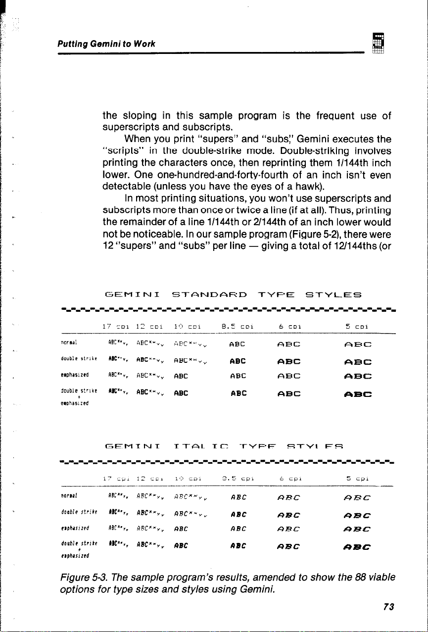
Putting Gemini to Work
the sloping in this sample program is the frequent use of
superscripts and subscripts.
When you print “supers” and “subs:’ Gemini executes the
“scripts” in the double-strike mode. Double-striking involves
printing the characters once, then reprinting them 11144th inch
lower. One one-hundred-and-forty-fourth of an inch isn’t even
detectable (unless you have the eyes of a hawk).
In most printing situations, you won’t use superscripts and
subscripts more than once or twice a line (if at all). Thus, printing
the remainder of a line 1/144th or 21144th of an inch lower would
not be noticeable. In our sample program (Figure 5-2), there were
I2 “supers” and “subs” per line - giving a total of 121144ths (or
GEMINI
_____ -- . .._ ----.
NVDa!
double strike
raphrr!zPd
double strlkr
ophaslzrd
17 cp1 12 cc1
+
bBC”‘,.
DW’,,
RBC”,,
ttw,,
.----.-.-.-
ABCX-Y,
MC*-,,
RRC”-Y*
RRCX-Y,
I-l-aI-IC
1’:’ co1
ARCXXY,
RRCX- Y”
ABC
RBC RBC
TYF’E STYLES
2.5 cpl
~--
/?)BC
c)BC
ABC ARC URC
t cpl 5 cpl
ARC
UBC
UBC
URC
URC
RRC
Figure 53. The sample program’s results, amended to show the 88 viable
options for type sizes and sty/es using Gemini.
73
Page 80

Gemini User’s Manual
1/12th) of an inch difference between the beginning and end of the
line.
By examining the lower table in Figure 5-3, you’ll see that the
same options and parameters apply to italic type as to standard
type.
--
-
WORD PROCESSING SOFTWARE
Word processing is the family of programs that package text in
forms understandable by your microcomputer, its display monitor,
and various printers. Popular word processing programs include
Wordstar, the Electric Pencil, Easywriter, Word Handler, Perfect
Writer, etc. (Note: Each of these programs is the copyrighted
property and registered trademark of the companies that own
them. They are mentioned here only as examples of commercially
available word processing programs.)
Most of the popular word processing programs were written
a few years ago, when printers were simpler devices, capable of
performing far fewer options than are available with Gemini.
For example, most current word processing programs can
send function codes for printing “bold” type (double-striking). To
accomplish this, the word processing software sends multiple
instructions (initiated by keyboard commands such as “control-
B” or “control-E”). When older printers receive these instructions,
they print a word, then get the signal for their printing mechanism
to back up, then respond to another signal that tells the “dumb”
printer to print the word again. With Gemini, the function code ESC
“E” tells the smart printer to automatically double-strike using
the LPRINT command conveyed in BASIC.
Don’t be discouraged if you bought a word processing
package and it seems inadequate to utilize Gemini’s full
capabilities. Gemini can do just about anything your word
processing software can tell it to do, and then some. There are four
solutions to the problem.
-
-
-
-
-
The BASIC Solution
One solution to the limitations of word processing software is not
to use it when you want to make full use of Gemini’s potential
performance. You can learn BASIC and put it to work.
74
-
-
Page 81

Putting Gemini to Work
Even without “mastering” BASIC, you’ll be able to work
wonders with Gemini, a.s you’ve already learned in this chapter.
User-Patching Your Software Program
“Patching” is the term used to describe making changes in an
existing word processing program so that it can make fuller use
of Gemini’s capabilities. To accomplish patching, refer to your
word processing software user’s manual. The manual should have
a listing that demonstrates “user-patchable” changes you can
make in the program.
A word of warning: You need to be computer-wise to
successfully patch an existing word processing program. Before
you start, it’s probably a good idea to make a copy of your word
processing program and attempt patching the copy. That way, if
you make an error, you’re only out the time you invested and
haven’t hurt the “original?
Software Patching Setvices
Another solution to the problem of software/printer incompatibility
is to turn to one of the “software recycling” services that advertise
in hobbyist computing publications.
For a modest sum, they will “recycle” your software by
performing the patching operation for you. Many of these services
invite you to mail them your word processing software (and, of
course, a check), and they’ll send you back a “tailored-to-fit”
program on your same diskette(s).
The Creative Solution
If you made it through the program listed in Figure 5-1, you should
be able to create a simple program that serves as
“Your Own Word Processing Software System.”
(The title’s a bit long; you can always “word process” it to
something short and snappy.) Even if you didn’t successfully
execute the sample program, don’t be afraid of trying this task.
Remember: You may never know if you can do something unless
you try.
75
Page 82

Gemini User’s Manual
10 CLS:KEY 3FF:DM AS(24,BO)
20 cLs:X~l:Y:l
30 SOSUB 1SO:LOCATE X,Y:PRINT “C”
40 B$=INKEYI:IF B+“’ THEN 40
SO IF B$aCHR¶(S) THEN CL&END
50 IF BI=CHRI!lB) THEN CLS:SOBUB 200:60TO 20
70 IF BJ=CHRl(lb) THEN 6010 220
“C”: : SOT0 40
90 IF BWHR((4) THEN SOSUB 130:GOT0 40
100 LOCATE X,Y:PRINT BJ;:RI(X,Y)+:Y=Y+l
110 IF YgBO THEN A$(X,Yl=CHR((l3):BEEP:X*X+l
120 LOCATE X,Y:PRINT “@“;:GOTO 40
130 LOCATE X,Y:PRINT ” “i:Y:Y-1:IF Y=O THEN
!35 A5(X,Y)=“”
140 LOCATE X,Y:PRINT “~*;:RETuRN
!50 LOCATE 25,2:COLOR O,?:PR!NT ” ^P) printer “::
160 LOCATE 25,17:COLOR 0,7:PRINT ” ‘D) delete “::COLOR 7,0
170 LOCATE ?S,JQ:COLOR O,?:PRINT @ ^A) restart “::COLOR !,O
180 LOCATE 25,5!:COLOR O!?:PRINT ” “El exit “::COLOR 7,o
:90 RETURN
200 LOCATE !0,30:PRINT “olease stand bv “;:FOR I=1 TO X:FOR Jzl TO SO:M(I,J)=““:
NEXT: NEXT: RETURN
220 LPRIN? CHRb(27) : ‘@”
230 CLS:LOCATE 25,?:COLgR 0,7:PRINT ” Clonnand “: :LOCfiTE 25,16
‘40 PRINT ” Pjrint
c
250 G$=INKEY):IF 65=“’ THEN 250
200 IF 6l=“P” THEN SOSUB 310
270 IF G§=“C” THEN GOSUB 320:GOT0 230
280 IF S$=“R” THEN 6OSUB 300:GOT0 30
290 GOT0 250
300 CLS:FOR 111 TO X:FOR J=l TO BO:LOCATE 1,J:pRINT M(I,J);:NEXT J:NEXT
319 FOR I=1 TO X:FOR J=l TO SO:LPRINT AS(I,J);:NEX? J:NEXT I:RETURN
320 LOCATE ?!,::PRINT STRINM(S0,32!:
330 LOCATE 25,2:PRINT STRINGS(50,32):
340 LOCATE 252:COLOR 0,‘I:PRINT ” El Ese “;:LOCATE 25,ll
350 PRINT ” Cl CHRt
360 GI=INKEYI:IF G$=“” THEN 3bO
370 IF Gs=“E” THEN 60SUB 420:SOTO 400
380 IF 65:“;” THEN SOSUB 530:GOT0 400
390 IF G+“Q” THEN GOT0 410
400 GOT0 360
410 RETURN
“::LOCATE 25,27:PRINT ” Rleturn “::COLOR 7,O
“;:LOCATE 25,21:PRINT ” 01 end conmand “t:COLOR 7,0:STI=“”
Y.l:GOTO 40
=l:BEEP:
- SO IF B(=CHR%(13) THEN AJ(X,Y)=BhLOCATE X,Y:PRINT ’ “:X=X+l:Y~l:LOCRTE X,Y:PRINT
-
--
-
-.
IIRETURN
76
Page 83

Putting Gemini to Work
420 1:O:LOCATE 23,4:PRINT “Esc “;
430 6%=fNKEYS:IF 61:“” THEN 430
440 IF WCHR$(l3) THEN 480
. .
450 PRINT 6s;
460 PRINT ” “;
47b s~(I)*6~lI~I+lr6Ot0 430
b
I
480 IF 112 THEN FOR Jli TO IID~~DI+S$(J~:NEXT JrSTWHRI(27)+SRiO)
+CHRI(VAL(Dt)1rDW”
490 IF I-2 THEN STWHRS(27J+SS(OI+CHR$WALWfl1 t 1
SO0 IF I*1 THEN StWHR1127)+S1(0)
510 LPRINT ST$iSTS*“‘:FOR J=l TO I:SS(J)~““:NEX? J:I*O
520 LOCATE 23,4:PRINT ”
530 LOCATE 23,2:PRINT “CHRI “;:STl=“”
540 G$~INKEYhIF SW” THEN 540
550 IF SS=CHRS(13) THEN 570
560 PRINT 6Q:STWTI+GS:60TO 540
570 LOCATE 23,2:PRINT ”
‘:LPRINT CHRSWAL(STO)::STC=““:RETURN
“; :RETURN
Figure 54. A simple program, written in BAStC, that serves as a rudimentary
word processing program.
In Figure 5-4, a very simple word processing software program is presented, written in BASIC for the IBM-PC. This program
leaves some room for improvement, but after all - it’s free. You
might apply it to writing short letters or other simple documents.
The display on your CRT monitor may not be anything to write
home about, but at least it gives you the capability of writing
home! You may also find the use of the control codes is somewhat
awkward, but this program has its own menus which will make it
easier for you to remember the commands. The program provides
three different menus which display your options and prompt you
to select specific commands to guide you in your word process-
ing. After you have typed in the program and entered RUN followed by a carriage return, the first menu will appear at the bottom
of the screen and the cursor should be at the top left corner.
Now you can type in your text and correct any errors you may
make. Because of the simplicity of this program, it does have some
limitations, which will vary for the different computers. If your computer is an IBM-PC, you can type in 23 lines at up to 80 characters
per line. Some other computers may not have the capacity to accept this many characters, limiting the amount of text you can
type. This program is also restricted in that errors can only be corrected on the present line. Once you have hit <return > you can-
not go back to the previous line to revise it.
77
Page 84

Gemini User’s Manual
After typing your text, you may go either to the second menu,
which will permit you to print your text, or to the third menu where
you may send Escape or control codes to the printer for special
characters or effects. It is not necessary to type the entire ASCII
codes. Instead, you have the option of selecting “ESC” or “CHR$“.
For example, if you wish to send CHR$(27); “W”; CHR!$(l); to the
printer for printing of wide characters, you simply need to seiect
the “ESC” option and type “Wl” and then hit c CR>, and the code
will be sent to the printer. After sending the codes, you may gc
back to the 2nd menu and print your text again.
-
-
The following is a listing of the commands:
CONTROL COMMANDS FOR THE “DO-IT-YOURSELF”
WORD PROCESSING PROGRAM (SHOWN IN FIGURE 5-4)
1st MENU
A P = gets you to the 2nd command level
AD = deletes the character to the left of the cursor
AR = restart: clears the screen and lets you type a new text
*E = exits the program
2nd MENU
P = prints your text
C = gets you to the 3rd command level
R = returns you to the 1st print level
3rd MENU
E(ESC) = lets you send ESC code with an abbreviated
command
C(CHR$) = lets you send a control code with an abbreviated
command
R = returns you to the 2nd level
-
-
78
These commands may vary if you are not using an IBM-PC, but
the effects will be the same. For further explanation of the program
variations, please refer to the computer-specific appendices at the
back of this manual.
-
Page 85

F
6:’
/
1
Putting Gemini to Work
WHERE DO WE GO FROM HERE?
If you want to get to work, you may take your leave at this point.
You’ve gotten a good idea of what Gemini is all about - how the
parts fit together, how to add paper and ribbon, the Self-Test, interfacing with your computer, and various printing capabilities.
That should be enough to get you started.
To paraphrase an old saying: “A journey of a thousand pages
begins with a single character.” Bon Voyage!
If you have the luxury of enough time to keep reading, the next
five chapters and accompanying appendices will provide you
with the means to be able to travel first class. If knowledge is
power, then you’ll be a powerful Gemini user by the end of
this manual.
79
Page 86

-
-
Page 87

Understanding dot-matrix printing and Gemini’s graphics begins
with knowing some details about the print head and the software
that controls it. This chapter will provide you with those details.
The print head, print matrix, and vertical spacing are described in
understandable terms. The second half of this chapter will
introduce you to dot graphics: the control codes for firing the
“pins:’ and a sample graphics program that will put a smile on your
paper, and perhaps on your face.
THE PRINT HEAD
The print head contains nine thin wires, or pins, positioned one
above the other. Figure 6-1 illustrates the print head, from the
paper’s point of view, looking straight on. Each wire is connected
to a solenoid “gun;’ an electromagnet that “fires” when told to do
so by the “computer” inside Gemini. Figure 6-2 presents a
schematic of the print-head mechanism, profiling the solenoid,
spring, and dot-wire pin for one of the guns.
THE FUNDAMENTALS OF
DOT MATRIX PRINTING
7-bit interface
il
O-bit Interface
3
Upw
Lower
Needle of
print head
n
B==
Figure 6-1. The bit-image column-scan capability is the result of nine
pins, stacked in a column, each “fired” independently in response to
signals from the 7-bit or a-bit interface from your computer.
81
Page 88

“Needle” pin
Sprlng
Gemini User’s Manual
Paper
-
Platen
Pln gulde
r
$- Iron core
I
Clapper
Figure 6-2. This side-view schematic of the print-head mechanism shows
how electrical signals to the solenoid cause the clapper to “fire” the
needle-like pin that impacts the ribbon/paper/p/a ten. After the solenoid
releases the clapper, a spring returns the pin to its original position.
instructions sent by your computer and directs the print head to
discharge the correct pins in the proper order. The result of this
“hiring” and “firing” is the printed characters produced by Gemini _
onto your paper.
letter “H” (see Figure6-3). Because the print head is bidirectional
(can print right to left, and left to right), Gemini can start the “H”
from either side.
one side of the letter. Then, the print head moves across the paper,
and pin number four fires three times to create the horizontal line.
Finally, the top seven pins fire simultaneously again to complete
the othervertical line. Aside from the amazing fact that the entire
printing operation just described can take place in approximately
one-hundred and twentyth of a second, all this activity is
caused by a single ASCII code signal.
\’
Printer solenoid
Gemini’s built-in “computer” reads the ASCII code
Consider, if you will, the process of printing an uppercase
In this example, the top seven pins fire simultaneously to print
Bobbin
‘IL
I
Ribbon guide
82
Page 89
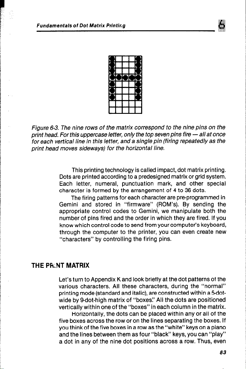
Fundamentals of Dot Matrix Printkg
Figure 6-3. The nine rows of the matrix correspond to the nine pins on the
print head. For this uppercase letter, only the top seven pins fire - all at once
for each vertical line in this letter, and a single pin (firing repeatedly as the
print head moves sideways) for the horizontal line.
This printing technology is called impact, dot matrix printing.
Dots are printed according to a predesigned matrix or grid system.
Each letter, numeral, punctuation mark, and other special
character is formed by the arrangement of 4 to 36 dots.
The firing patterns for each character are pre-programmed in
Gemini and stored in “firmware” (ROM’s). By sending the
appropriate control codes to Gemini, we manipulate both the
number of pins fired and the order in which they are fired. If you
know which control code to send from your computer’s keyboard,
through the computer to the printer, you can even create new
“characters” by controlling the firing pins.
THE PkNT MATRIX
Let’s turn to Appendix K and look briefly at the dot patterns of the
various characters. All these characters, during the “normal”
printing mode (standard and italic), are constructed within a !5dotwide by g-dot-high matrix of “boxes? All the dots are positioned
vertically within one of the “boxes” in each column in the matrix.
Horizontally, the dots can be placed within any or all of the
five boxes across the row or on the lines separating the boxes. If
you thinkof the five boxes in a row as the “white” keys on a piano
and the lines between them as four “black” keys, you can “play”
a dot in any of the nine dot positions across a row. Thus, even
83
Page 90

Gemini User’s Manual
though there are only five boxes across, you have “9x9” printing
positions.
The uppercase letters are formed by the top seven pins. Some
of the lowercase letters (“9:’ “j:’ “p:’ “q:’ and “y”) extend down to
the eighth and ninth pins. This style of character generation, called
“true descenders:’ makes these letters much more readable.
The “underlining” character (ASCII code 95) is created by
firing only the ninth pin. The ESC CHR$(48) control code can also
be used for underlining.
The block graphics characters (ASCII code numbers 224
through 255) are configured on a “6 x6” matrix. We’ll discuss these
characters a little later. A simple example of block graphics is
shown in Figure 6-4: “W” “y” for the “Cowboy” state. (The BASIC
program for producing Figure 6-4 is presented and discussed in
Chapter 7.)
Figure 6-4. Using block graphics and a simple program written in BASIC,
you can create very large type, as shown here.
Although the matrices are the same width, the dot
configurations of the different characters in the alphanumeric and
special symbol sets are different in their widths. The narrowest
letter is the lowercase “i” (ASCII code 105); the smallest character
is the fourdot period (ASCII code 46). The widest characters in the
alphanumeric set are the uppercase letters, such as “M” (ASCII
code 77).
When Gemini prints these characters, for example, during the
first lines of the Self-Test, an extra “blank” column (a sixth
column) is added to each character to provide spacing between
them.
When you shift into the elite (12 CPI) or compressed mode
(17 CPI), the characters are the same height as in the normal mode,
but vary in width. With elite and compressed printing, the
“columns” of the matrix become narrower.
84
-.
Page 91

fundamentals ot Dot Matrix Printing
With emphasized type, the matrix is 18 by 9 because each
column is fired twice, horizontally offset by one-half dot on the
second firing. Double-strike printing is accomplished by an 18 by
18 matrix, with the second printing vertically and horizontally
offset by one-half dot. Emphasized plus double-strike is a 36 by
27 matrix, with the additional printings offset both horizontally and
vertically.
L
In the double-width (“expanded”) mode, a column is printed,
the print head moves over and repeats the same column
configuration, then the print head moves over to twice-print the
next column.
Superscripts and subscripts follow the same matrix pattern
as the standard characters, but the print size of the matrix is onehalf as high.
b”.
L..
t..
cr..
k.“.
L..
L.
11.
VERTICAL SPACING
On most conventional typewriters, you have a choice of single,
space-and-a-half, or double spacing. Your Gemini can print lines
that are set to one-sixth inch, or one-eighth, or whatever spacing
you want in increments as small as 11144th of an inch!
When you “initialize” your printer, Gemini is automatically
set to avertical spacing of one-sixth inch if DIP Switch l-5 is “on”
or one-eighth inch if DIP Switch l-5 is “off? One-sixth inch spacing,
which delivers six lines per inch, is the same as a standard “pica”
typewriter, and is fine for text printing.
For block graphics (each of which is up to six dots tall),
different spacing is required (or else your graphic “blocks” won’t
fit together tightly).
Anticipating that you would want to be able to adjust the
vertical spacing, Gemini provides you with the following five ways
to make adjustments:
Software
Code
ESC “2”
ESC “0” 118
ESC “1” 7172
ESC “A”n n/72
ESC “3” n
Height
(Inches)
116
n/l 44
Vertical
Dots
12
9
7
n
n/2
k.
85
Page 92

Geminl User’s Manual
As if that weren’t enough, there’s ESC “J” n, which does the same
work as ESC “3” n but doesn’t change the value for successive
line feeds.
Because each “dot” is l/72-inch in diameter, you have vertical
spacing control as miniscule as half the thickness of a dot!
Another way of expressing the same idea is that Gemini provides
a high-resolution graphics pattern of 144 dots per vertical inch.
With Gemini’s ultra-high horizontal resolution capability of 240
dots per inch, that makes for a powerful graphics tool, no matter
how you look at it.
In Figure 6-5, you’ll see 1/144th-inch resolution, as well as the
appearance of other “leadings” (pronounced “leddings”). Leading
or line spacing is the amount of space set between lines of type.
Figure 6-5 presents sample leadings of 1/144th inch to
approximately 115th inch. If you want to run the sample program
that produces Figure 6-5, it is presented in BASIC. If you want to
run this program, the following paragraphs discuss the “what’s
and “why’s:’
A Sample Program that Demonstrates Vertical Spacing
The program presented in Figure 6-5b is short but takes awhile to
print. In the program, the first line prints a heading, a built-in title
for your graphics. Line 20 starts a loop from 1 to 30: This loop
controls the vertical spacing.
Line 30 may look strange, but it reveals an important part of
the limitations of BASIC. Although the language is easy to use,
it has a few quirks. In this case, a CHR$ code is intercepted by
BASIC and used as a BASIC control code that is then sent to the
printer.
CHR$(13) is a code for a carriage return. Microsoft BASIC
can’t resist inserting a line feed, CHR$(lO), behind every CHR$(13)
that it handles en route to the printer. The computer language
doesn’t know that this particular CHR$(lO) is the final character
in the ESC “3” n command that tells Gemini to change the
“leading” (line feed) to 13/144ths inch. There are ways to get
around the problems (using the POKE statement, for example). For
this program, we will bypass the problem and go to line 110 when
the loop counter (I) equals 13.
86
_
Page 93

Fundamentals of Dot Matrix Printing
Line 40 reveals that the variable M is used to control the
number of times line 90 is executed. When I is small, M is large.
When I is greater than 12, M is fixed to 2. Line 50 sets the vertical
line spacing (you may recall that ESC = CHR$(27), “3” =
CHR$(Sl)). So, in this program, line 50 sets the vertical spacing to
11144 inches.
Line 60 starts a loop that uses the value of M to count 25 times
when I equals 1, and counts 3 times when I is greater than 12. Line
70 prints a message telling us the value of the line spacing on the
next-to-last line of the M loop. Line 80 spaces over the printing
done by line 90 to column 30 by using the BASIC TAB statement.
Line 90 is where the action is. This line is similar to line 140
in the first reference program and prints 40 characters; its ASCII
code is 241. This character is a six-dot straight line that is part of
the block graphics set.
Line 100 and 110 end the J loops, and line 120 resets the
printer and ends the program.
Discussion of the Vertical Spacing Program
Let’s start by looking at how close the dots are vertically in Figure
6-5. Remember that the normal characters are seven dots high,
which is 141144ths (7/72nds) of an inch. Therefore, if you wanted
to print text, say in all uppercase letters, with each line resting atop
the next, you’d set the vertical spacing at 14/144th of an inch.
When we use block graphics (where each block is 6 dot-
spaced high), we set the vertical spacing to 6/72 (or 12/144) inches.
The maximum value of n allowed for the vertical spacing
control code is 127. The result is that almost one inch (127/144ths)
for the ESC “3” n code, and roughly l-314 inches (127/72nds) for
ESC “A” n.
In the sample program, we stopped I at 30, so the printout
would fit on a standard 66-line sheet of sprocket-fed paper. If you
wish to, you can replace the loop limit on line 20 with 127, and run
the program again. You might also try replacing the CHRS(51) with
CHR$(65) on line 50 and run the program using the n/72-inch
vertical line spacing mode.
87
Page 94

GeminiUser'sManual
High-Resolution Vertical Spacing Using the ESC 3 n Control Code
11144
21144
31144
41144
51144
61144
71144
81144
91144
101144
111144
121144
141144
151144
161144
171144
181144
191144
-- -
--- -_I--
--__I-
--I_ ---
---
-------
-------1------------
------- -------
-------------
--
---..--
-
-
-
--
--
-
-
--
--I -
-
201144
---------
----------
m---1_
---
--
211144
221144
----m-m- -------- ------em
-
------__--_--------I-
Figure 6-5a. This printout (actual size) shows the vertical spacing that you
can control using the ESC 3 n code. This printout was created using the
BASIC program shown at the bottom of Figure 6-5b (a continuation of this
figure).
88
-
Page 95

Fundamentals of Dot Matrix Printing
Inch
Spaclng
231144
241144
_------------------------------------
_----e--------m- 1--e------------p
-----------------------------~
----__---------
----------_---_---_^______ --
--a-----
25/l 44
261144
------ ---
27/l 44
--- -----m-----------w
---- ~~~~ ----I------_I_
-v----m
--
28/l 44
---
i0 LPRINT TAB(30);“High Resolution Vertical Spacing *
----
15 LPRINT TbB(30)~“Using the ESC 3 n Control Cod@ ”
20 FOR I * I TO 30
SO IF I = 13 THEN 6020 110
40 M * INT ( 144 I ( 6 t I 1 1 : !F II { 2 THEN H = 2
50 LPRINT CHR1(271; CHRt(Sll;CHRS(Il:
60 FOR J = 0 TO M
70 IF J = t-1 THEN LPRINT I : “/144 INCH SPACINS”;
80 LPRINT TRB(30)i
90 FOR N * 1 TO 401 tPRINT CHR$(2411; : NEXT N: LPRINT
100 NEXT J
110 NEXT I
120 LPRINT CHR$(27);“@“: END
--_
--
Figure 6-5b. This continuation of Figure 6-5a depicts a more “open” spacing,
that you might use for prin ting drafts of documents that need room for letting
the reviewer manually insert changes. This printout was produced by the
BASIC program listed above, written for the IBM-PC. Consult the appendices
to learn how to adapt this program to other computers.
89
Page 96

INTRODUCTION TO DOT GRAPHICS
When we enter into the bit-graphics mode, we have complete
control over the firing of each individual pin in the print head. The
graphics mode opens up the full potential of the Gemini printer
by allowing us to create any image we can imagine. When printing
dot graphics, Gemini can produce an ultra-high-resolution image
(at 240 x 144) of over thirty thousand dots per square inch!
There are 80 characters, for example, in an 8inch-wide line
of text set in 10 CPI. For the same line width, you can print 136 -
condensed-width (17 CPI). As a point of comparison, you could fire
up to 480 dots per line (that’s 60 dots per linear inch) in the “low”
resolution graphics mode. In the ultra “high” resolution graphics
mode, you could print graphic images with a precision of 1920dots
per line (four times the number of “firings” per line-inch as in “low”
resolution). “Dot’s” a lot of dots.
Fortunately, we don’t have to fill all the columns on every line,
any more than a painter must apply all available paints to a single
canvas.
After telling the printer to enter the graphics mode, we then
define how many columns of dots we want to print in a line. We
can send Gemini a string of instructions that tell which dots we
want to fire in each column. A line-feed command can be used to
conclude the graphics command sequence. We can repeat the
graphic-mode commands, if that’s the goal, to repeat the graphic
mode commands over and over or to fill an entire page with dot
image graphics.
Gemini User’s Manual
Graphic Control Codes
The low-resolution graphics mode is entered by sending Gemini
a four-character control code:
ESC “K” nln2
where,
ESC is the character represented by ASCII
“K” is the character for ASCII code
90
code CH R$(27)
CHR$(75), which signals Gemini to put
low resolution into effect.
Page 97

F undamenta/s of Dot Matrix Printing
Note: If we used ‘I” or CHR$(76)
instead of “K:’ we would be asking
Gemini for high-resolution graphics.
If we used “y” or CHR$(121), we would
be asking for high-resolution graphics
with double speed, and if we used
“2” or CHR$(122), we would be asking
for ultra-high-resolution graphics at
normal speed.
nl and n2 represent the set of ASCII
codes that define how many columns
of graphics to print on a line. If you
want to print “x” number of columns
of graphics on a line, then:
nl is the remainder of x/256, and
n2 is the quotient of x/256
Note: For those of you who are
computer-wise and curious:
nl = x
MODULO 256, and n2 = INTEGER of
xl256
What does all this mean to the rest of us? The following table
might help.
If the number
of columns,x,
ranges from:
1 to 255
256to 511
512 to 767
768 to 1023
1024 to 1279
1280 to 1535
1536 to 1791
1792 to 1920
then,
nl Is
x-x256
x- 512
x- 768
1024
X-
x - 1280
x - 1536
x-1792
then
n2 is
0
1
2
3
4
5
6
7
Remember: Gemini-70X can only print up to 480 columns in
low-resolution mode, 960 columns in high-resolution mode, and
1920 columns in ultra-high-resolution mode. The Gemini-15Xcan
print 816 columns in low resolution, 1632 in high-resolution, and
3264 in ultra-high-resolution.
91
Page 98

Gemini User’s Manual
Gemini requires that precisely the correct number of
characters you specify with nl and n2 will follow immediately after
the n2 control code. If there are too many (or too few) characters,
unexpected and crazy things will happen.
The high-resolution graphics mode is entered by sending Gemini
the control code:
ESC “L” nln2, which selects the 120 dots-
per-inch column scan bit image
graphics mode.
But Gemini’s graphics capabilities don’t stop there. The Gemini10X/15X, with control codes ESC “y” nln2 and ESC “z” nln2, will
take you two steps beyond high-resolution graphics, and allow you
to print faster and with even greater density.
ESC “y” nln2 commands the printer to
print dual-density graphics with
double-speed. In other words, your
result will be high-resolution graphics
(as if you had used ESC ‘IL”) but they
will be printed twice as fast!
ESC “z” nln2 puts Gemini in the quadruple-
density graphics mode (even more
dots per inch). The result of this ultra-
high-resolution mode is the capacity
to print 1,920 dots in one line on the
Gemini-lox, and 3264 dots in one
line on the Gemini-15X. (See the explanation of nl and n2 for ESC “K” to
define how many columns of dots
you want to print in a line.)
-
Firing the Pins
There are nine pins in the Gemini print head. In the graphics mode,
you can control the upper eight. For those of you with computers
that can only send seven bits (Apple II and some others), you
control the top seven pins. Let’s look at the print head again and
label the pins as follows:
92
Page 99

Fundamentals of Dot Matrix Pfinting
Print Head
Pin Number
Print Head &Bit
(toIN
7
.
.
.
.
.
.
.
.
.
d
Interface
128
64 64
32 32
16 18
not used
8 8
4 4
2 2
1
7.Bit
Interface
ns: used
1
not used
Based on the chart presented above, if you had a 7-bit
computer and wanted to fire pins number 1 and 4 simultaneously,
you would send CHR$(64+8). In other words, you’d send CHR$(72):
Therein is the pattern. Thus, if you wanted to fire all the pins, using
an 8-bit computer, you’d send:
CHR!$(128 + 64 + 32 + 16 + 8 + 4 + 2 + 1) = CHR$(255)
Control
Code
CHR$(128)
CHR$( 64)
CHR$( 32)
CHR$( 16)
CHR$( 8)
CHRS( 4)
CHR$( 2)
CHR$( 1)
CHR$( 0)
CHR$(255)
CHR$( 72)
Binary
Representation
10000000
01000000
00100000
00010000
00001000
00000100
00000010
00000001
00000000
1 1 1 1 1 1 1 1
01001000
Pin
Fired
#l
#2
#3
#4
#5
#6
#7
#8
none
all 8
#2
93
Page 100

Gemini User’s Manual
You computer aficionados may have already figured out that
the high-order bit of the character controls the top pin, the next
bit controls the number-two pin, etc.
Okay, now that you know how to fire the pins, what code do
you think will fire pins no. 5,6, and 8 with an 8-bit interface (per
the above chart)? How about CHR$ (8+4+1), or CHR$(13)? That
may seem like a good answer, but (in the words of Hamlet) ‘lay,
there’s the rub:’
CHR$(13) causes BASIC to automatically insert a line feed,
CHR$(lO), behind it. These BASIC programs were written several
years ago, before Gemini came along. Gemini is smart enough to
use CHR$(13) for a purpose other than initiating a carriage return;
if only BASIC were as smart.
One solution to the above problem is to design your graphics
programs so that they only use pins numbers 1 through 7 for 8-bit
computers, and numbers 1 through 6 for 7-bit. Because the bottommost pin that normally can be used is fired by CHR$(l), all
commands for the other usable pins will be even-numbered
(whatever their combination of numbers to fire whatever
combination of pins). With all the codes even-numbered, there’s
no need to concern ourselves about unlucky old CHR!$(13). You
might want to think about it for a while. There are other ways
around the problem, but the even-number approach works (even
if there seems to be something odd about it).
-
-
-
-
Example Graphics Program
Now that we’ve learned how to send the graphics controls to
Gemini, let’s construct a simple character to test low-resolution
printing. This program will show you one approach to creating
graphic images. In the next chapter, we’ll consider more advanced
techniques.
The first step in generating a sample program is to decide
where to position the dots. One way is to start with a pencil and
a piece of paper, especially paper with square grids printed on it.
We will imagine that one dot will cover one square.
94
-
 Loading...