

Page 1

OPERAIIONS MANUAL
Bedienungsanleltung
Manual de funcionamiento
Manual de fonctionnement
Manual del utente
XL-500 ll
iillll1lll
g
1111
0
5
Ill
Ill1
0
DIRECT-DRIVE MANUAL TURNTABLE
Handdrehscheibe mit Direktantrieb
Giradiscos manual de accionamiento directo
Table tournante manuelle CI entrainement direct
Ill 1111111~
Girad
ischi manuale a comando di
retto
For assistance and information in the
U.S.A.
Multi Language
English
Deutsch
Espaiiol
Francais
Italiano
. . . . . . . . . . . . . . . . . . . . . . . . . . . . . . . . . . . . . . . . . . . . . . . . . . . . . . . . . . . . . . . . . . . . . . . . . . .
. . . . . . .
..I..I....1.....I..I........I..........<.<..<.....I,.,...........I..
. . . . . . . . . . . . . . . . . . . . . . . . . . . . . . . ..‘..............<..........................
. . . . . . . . . . . .
. . . . . . . . . . . . . . . . . . . . . . . . . . . . . . . . . . .
..I....I......<...I............................................
cal1
toll free
1-800-476-8633
Instructions
..~.............I.........................
1
Page 3
Page 5
Page 8
Page 11
Page 14
Page 2
15 9
QO
I
I
20
Q
1
1
Q-
2
o-
3
Q-
17
3
18
3
4
3
L-
;
Page 1
Page 3
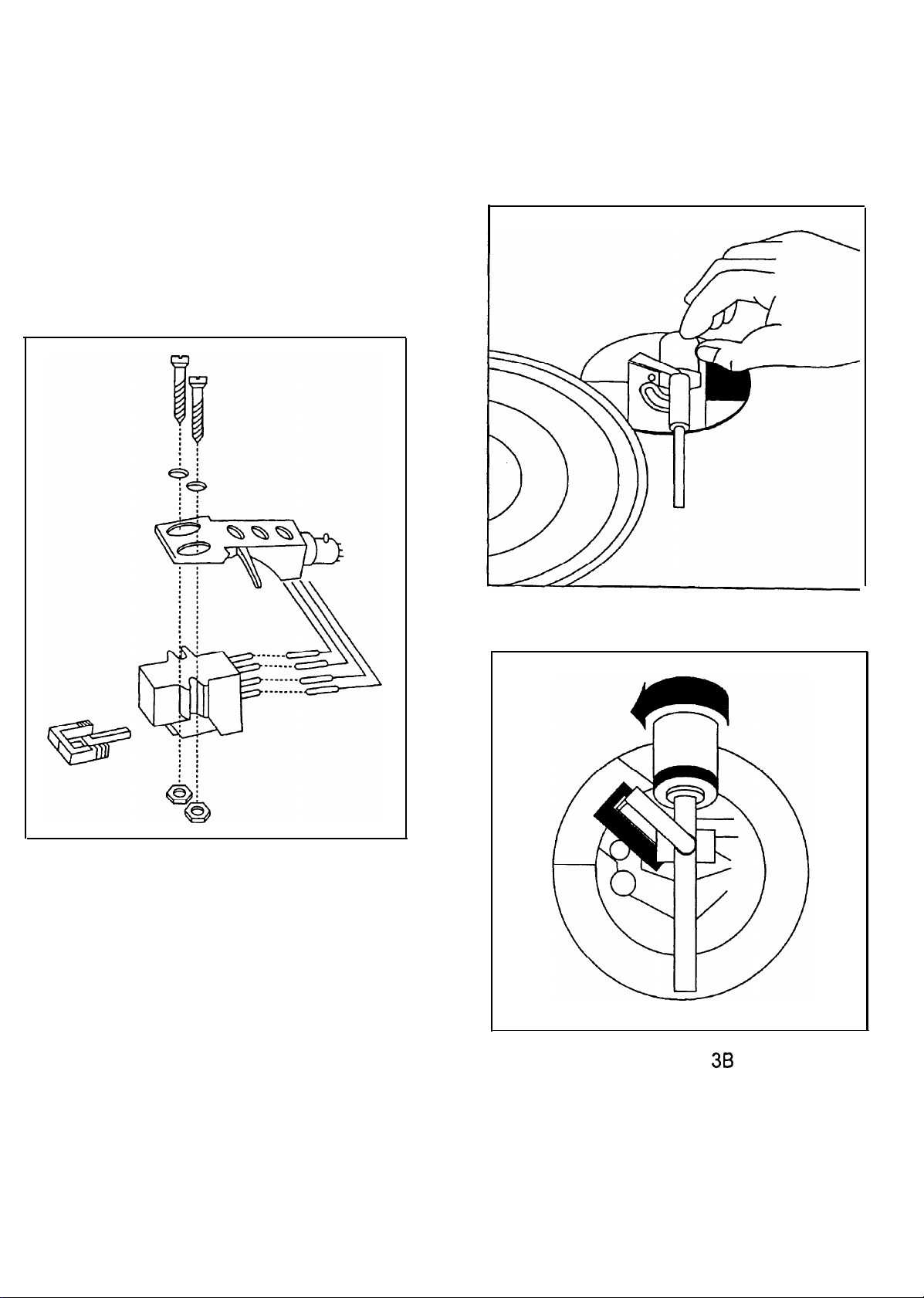
Figure 2
Figure 3A
Page 2
Figure
38
Page 4

Congratulations On
the
art tumtable indudes
you
carefully
read
l
flO% Pitch control
l
Bmking
. Strobe illuminator
l
Soft-touch starVstop switch
purchasing a Gemini XL-500 II tumtable. This
the
all the instructions.
for quick
latest features. Prior to use, we suggest
Stops
state
of
that
White
Blue
Red
Green
2
Mount the cartridge in the HEADSHELL (4) and tighten it with the
screws
included
AlTENTION
When using a Stanton 680 or similar cartridge, where the body
is
grounded to a cartridge terminal, remove the grounding strap
from the cartridge body to the cartridge ground terminal. Failure
to do this may
(L+)
. . . . . . . . . . . . . . . . . Left
(L-)...
. . . . . . . . . . . . . .
(R+)
. . . . . . . . . . . . . . . . . . . . Right
(R-) .,...............
with
the cartridge.
STANTON 680 CARTRIDGE USERS
result
in
..Left
Right Channel
excessive
hum.
Channel
Channel
Channel
+
-
+
-
1. Read all
2. To reduce the risk of
arc
Gemini Service Department or your authorized dealer to speak to a
qualified
/In
1-800-476-8633
3.
Tone Arm bearings
adjustment
4. Be
5. Cables should be low
sure that all
6. Always begin with the audio
minimum
seconds prior
‘POP”
7. DO NOT EXPOSE THIS UNIT TO RAIN OR MOISTURE.
8.
DO NOT USE
CONTROLS OR SWITCHES.
operating instructions before
NO USER
the U.S.A., if you have any
Sure that
that
Tumtable
Dust
Tumtable platter
45 rpm adaptor
Rubber mat.
Counter balance
Dust cover
Headshell
REPIACEABLE
Service
will void the warranty.
all AC power is OFF while making connections.
plugs
and the speaker volume
to tuming up
could result
ANY
unit
cover
hinge . . . . . . . . . . . . . . . . . . . . . . . . . . . . . . . . . . . . . . . . . . . . . . . . . . . . . . . . . . . . . . . . . . . . . . . . . . . 2
. . .
..-......................................................*........................
. . . . . . . . . . . . . . . . . . . . . . . . . . . . . . . . . . . . . . . . . . . . . . . . . . . . . . . . . . . . . . . . . . . . . . . . . . . . . . . . . . . . . . . . . .
. . . . . . . . . . . . . . . . . . . . . . . . . . . . . . . . . . . . . . . . . . . . . . . . . . . . . . . . . . . . . . . . . . . . . . . . . . . . . . . . . . . . . . . . . .
electn’cal shock,
PARTS INSIDE. Please conhct
technician.
for customer Service. DO
are
factory
set and sealed. Any attempt at
capacitance,
and
jacks
are tight and properly
level faders/volume
Ute
speaker volume to prevent
in
speakemxossover
SPRAY
. . . . . . . . . . . . . . . . . . . . . . . . . . . . . . . . . . . . . . . . . . . . . . . . . . . . . . . . . . . . . . . . . . . . . . . . . . . . .1
..,................................,.........................................
. . . . . . . . . . . . . . . . . . . . . . . . . . . . . . . . . . . . . . . . . . . . . . . . . . . . . . . . . . . . . . . . . . . . . . . . . . . . . . . . . .1
. . . . . . . . . . . . . . . . . . . . . . . . . . . . . . . . . . . . . . . . . . . . . . . . . . . . . . . . . . . . . . . . . . . . . . . . . . . . . .
CLEANER OR-LUBRICANT
using
this
equipment.
do not open the unit. There
Problems with
shielded and of proper length. Make
control(s)
set to OFF. Wait 8 to 10
this unit,
connected.
controls set at
darnage.
not
return
Ute
ON ANY
the
cal&
I
tfansient
1
1
1
1
1
HEADSHELL INSTALLATION:
Insert
the
While
LOCKING NUT (6)
HEAOSHELL (4) into
holding the HEAOSHELL (4) firmly in a horizontal Position,
ciockwise until the
COUNTERWEICHT INSTALLATION: (SEE
1.
Slide the COUNTERWEIGHT (7) onto the rear of the TONE ARM (5)
with the numbered stylus gauge facing forward.
2. Twist
the
COUNTERWEIGHT
onto the rear of the TONE ARM (5).
the
front of
Ure tubular
HEADSHELL (4) is
(7)
lightly
counterclockwise,
TONE ARM (5).
FIG.
turn
locked
in
3A & 3B)
to
screw
the
place.
it
ADJUSTING HORIZONTAL ZERO (0) BALANCE AND
smus PRESSURE:
1. Wlthout
2.
3.
4.
5.
6.
7. After adjusting the horizontal
touching
cartridge has a detachable one).
Release
REST (9).
Clockwise
cartridge
will
cause
counter clockwlse as
horizontally.
TONE ARM (5)
Place
TONE ARM (5) on ARM REST (9) and
ARM
CIAMP
With the
TONE ARM (5)
COUNTERWEIGHT (7) steady with one hand while rotating the
STYLUS
with the center line on the TONE ARM (5) rear shaft. The horizontal
zero (0) balance should be completed.
Refioat the TONE ARM to ensure horizontal
balance
has not been maintained, repeat counterweight
COUNTERWEIGHT (7)
recommend stylus pressure appears on the STYLUS PRESSURE
RING
(10)
shaft.
the
stylus tip,
the
ARM
ClAMP
advancement of the COUNTERWEIGHT (7) will
side of the TONE ARM (5) to be lowered.
the opposite.
You
PRESSURE RING
where it meets the
needed until the TONE ARM (5) is
tan
easily
Iwoats”
(8).
remove
(8) and lift the TONE ARM (5) off
Turn
the COUNTERWEIGHT (7) dockwise or
teil this
freely.
locked
(10) until
Zero
clockwise until
center
the stylus protector
Counter clockwise
by watthing for the
leck
on
the
ARM REST
the numeral ‘0” on the ring aligns
Zero
(0)
balance.
turn
the cartridge
line of
the
point
it in
place
(9)
hold
(0)
balance-
Ure balanced
manufacturer’s
TONE ARM (5) rear
(if your
cause the
balanced
Steps
the
ARM
where the
with
the
the
If
Zero
3 - 5.
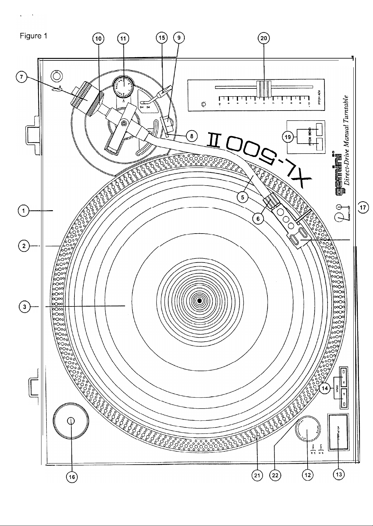
SEE FIG. 1 ( PAGE 1) FOR PART NUMBERS AND LOCATIONS.
TURNTABLE PLATTER INSTALLATION:
Set the TURNTABLE BASE (1) on a flat,
ensure that all
PLATTER (2) on
RUBBER MAT (3) on the PLATTER (2).
packing
materials have been removed, gently
the
center spindle of the TURNTABLE BASE (1). Put
level
surface. After
checking
place
the
to
the
CARTRIDGE INSTALLATION: (SEE FIG. 2)
Because all
particular cartridge’s
1.
Connect the lead
the terminals of most
wire to the terminal of the
cartridges
instructions to
wires
have their own designs, please refer to your
to
cartridges
insure
the cartridge
are
Same color.
color coded.
proper
installation.
terminals. For your convenience,
Connect
each
lead
ADJUSTING THE ANTI-SKATING CONTROL:
Set the ANTISKATING CONTROL
pressure.
(11) to
the
Same value
INSTALLING THE DUSTCOVER:
1.
Mount the
2. Hold
hinge bases into the holders mounted on the rear
3. Always raise the
4. Avoid opening and closing the
Vibration and
Page 3
hinges
onto
the dustcover
dustcover
stylus
the dustcover.
in Position, directly above the tumtable, and slide the
before removal.
skipping tan
dustcover during
result.
Panel.
play. Undesirable
as
the
stylus
Page 5

[ rN1T
PLACEMENT:
Place
unit on a flat. Vibration free
horizontaliy
Try to
Keep
stabiiize
place the
the
unit as far
unit away from
the
unit.
direct
surface.
Use the tumtable feet to
away
from the speakers as possible.
exposure to
the
sun, heat, moisture or
dirt.
Keep the unit weil ventilated.
‘ONNECTIONS:
1.
Plug the AC power plug into an appropriate outlet.
!. See Table A for proper connection of the output RCA plugs and ground
connector. Make
appropriate
connected to
Sure that
ja&.
To reduce hum, make
the
ground screw.
all the plugs are firmly plugged
Sure
into the
the ground iug is firmly
2.
When
ADJUSTING THE PITCH CONTROL:
The XL-500 II is equipped with a PITCH CONTROL (20). When the
PITCH CONTROL (20) is in the
45 depending on which SPEED SELECTOR BUTTON (14) is pushed.
When the PITCH CONTROL is positioned off
flO%
The PLATTER (2) is equipped with a STROBE RPM INDICATOR
STRIP (21) and the POWER SWITCH (12) contains built in STROBE
LIGHTS (22). When the PLATTER (2) is spinning, the STROBE
LIGHTS iliuminate the STROBE RPM INDICATOR STRIP. At 60 Hz the
bottom row of dots will appear to be stationary when
platter is exactly 45 RPM and
appear to be stationary at 33 RPM. At 56 Hz,
top represents 45 RPM and
TABLE A
PITCH BEND:
1. Pushing the PITCH BEND BUTTONS (19) will temporarily raise or lower
the pitch
retum
GND (Spade Lug)
t
L
(WHITE)
R (RED)
MIXER OR
RECEIVER
PHON0 L CHANNEL
PHON0 R CHANNEL
I
GND
Screw
not being used, the TARGET LIGHT should be
center
position the
tumed
Speed
will be 33 or
center, the pitch tan
depending on the position of the PITCH CONTROL.
the Speed
without
the pitch
the second
the
top row represents 33 RPM.
changing the slide setting.
to the siide
setting.
row from the
the second
Releasing
bottom
row from the
the
buttons will
off.
vary
of the
will
BASIC OPERATION:
1.
Place
a record on
(2).
2.
Select
Ure
SELECTOR BUTTON (14).
3.
Turn the POWER SWITCH (12) to
strobe illuminator (built into the POWER SWITCH (12) and the
indicator
(for
Remove the
Release the
Push the START STOP BUTTON (13). The tumtabie PLATTER (2) will
statt to
Spin.
Push
the
CUE LEVER (15) to the
Position the tone arm over
4.
5.
5.
7.
3.
the CUE LEVER to the “DOWN” Position. The TONE
siowly
lower onto the record at which
,3.
When play is over, raise the TONE ARM
(9). and secure it with the ARM
10. You now have
SWITCH (12) to the
pushing the START STOP
brake.
INTERRUPTING
1
.
Pushing
ARM (5) to iift stopping play.
Pushing
2.
TONE ARM (5)
was interrupted.
PLAYING 45 RPM RECORDS:
1.
When playing a 45 rpm record with a large
45 ADAPTOR (16) on the center spindle.
2.
Be sure that the
the 45
the
the
Speed indicator is
the
desired
Speed
the
seiected
stylus protector
ARM
CLAMP
RUBBER
MAT
(3) whi&t
by depressing the 33 or 45 SPEED
the
“ON” position, at which
Speed)
will illuminate.
(if
applicable
(8)
found
on
the
“UP” posiüon.
the
desired position on the record and push
time
CIAMP
(8).
the Option
of tuming off
“OFF”
position, or stopping the PLATTER (2) by
BUTTON
the
(13) and engaging
PLAY:
CUE LEVER (15) to
CUE LEVER (15) to the “DOWN”
to
siowiy lower onto the record at the
45
SPEED SELECTOR BUTTON
iliuminated.
the “UP” Position
sits
on
the
PLATTER
to your
cartridge).
ARM REST (9).
play will begin.
ARM (5) will
(5)
move it to
the
ARM REST
power by tuming
the electronie
will
cause
Position
will
Point
where play
center
hole, first
(14)
is pushed and
Point
Speed
the
POWER
the
cause
piace
the
TONE
the
the
TUFWTABLE
Type..
Drive Method
Motor
.....................................................................
Platter
..........................................
Speed
............................................................................
S tarting
Build-up Characteristics
Braking
Wow and
l
This
rating
effects
Rumble
SECTION:
....................................
................................................................
Torque
...................................................................
.....................
System..
Flutter
..................................................
..................................................................
refers to the tumtable assembly and platter only and
of
records, cartridges
.......................................................................
Direct
Aluminum
.0.8
or
toneams.
TONEARM SECTION:
...............................................
Type
Effective Length
Overhang
Effective Mass
Offset Angle
Friction
........................................
........................................................
......................................................................
.....................................................
......................................................................................
Tracking Error Angle.....Withi
O”32’
Stylus Pressure
Applicable
Headsheli Weight
Adjust
Range ..............................................
Cartridge Weight Range
......................................................................
GENERAL:
......................................................
Suppiy..
Power
Power Consumption
Dimensions
Weight
..................................................................... 22.5
Specifications are
dimensions shown are approximate.
.......................................................................
............................................................
subject to Change
Universal S-Shaped Tubular Arm
Less
n
2”32’
at the
at the inner groove of a 30 cm (12”) record
...............................................
without
Drive Manual Turntable
Direct
Drive
Diecast
sec.
standstillto33
Brtshless
13’
DC Motor
(332mm)
.33
113or45 RPM
1.2
Kg/cm
1/3
Dia.
RPM
Brake (Solenoid)
.0.02%
WRMS’
excludes
.56
dß Unweighted
.9
.9 1116”
g
(230.1 mm)
.19/32’
(15.2
mm)
(Without Cartridge)
22’
Than
7
mg
(Lateral, Vertical)
outer
groove
and within
5
0 -
10 g
6
-
5.6
115V&0Hz/230V-.50Hz
15 Watts
450mm x
17 3c x 6” x
152mm
Ibs. (
14”
x 352mm
10.2 Kg)
notice. The weight arid
g
g
I’ARGET
1.
Push
the TARGET
(18)
will
LTGHT:
iliuminate
LIGHT SWITCH (17)
the styius tip.
firmly
and the
TARGET LIGHT
Page 4
Page 6

Wir
gratulieren Ihnen zum Kauf eines Gemini XL-500 II Plattenspielers.
Dieses hochentwickelte erstklassige Gerät enthait die neuesten
Leistungsmerkmale. Vor Anwendung dieses Plattenspielers bitte alle
Anweisungen
sargfaltig
l
klO% Tonhöhenabstimmung
l
Bremsvomchtung
l
Strebelicht
durchlesen.
für Schnellstop
. Start-/Stop-Funktionstaste
1. Vor
Anwendung dieses
Getits
bitten alle Anweisungen sorgfältig
durchlesen.
2. Das
Getit
nicht
offnen,
um das Risiko elektrischen Schocks zu
mindern. Es enthält KEINE VOM ANWENDER ERSETZBAREN TEILE.
Die Wartung darf nur von befahigten Wartungstechnikern durchgeführt
werden.
3.
Die Tonarmlager sind werkseingesteilt und abgedichtet. Jegliche
Anderungsversuche
4. Darauf achten, da beim
machen die Garantie ungültig.
Anschlu
die Wechseitromleistung abgeschaltet
ist.
5. Nur kapazitätsarme, abgeschirmte
Kabel
vorschriftsmäiger
Länge
benutzen. Darauf achten, da alle Stecker und Buchsen fest
angeschraubt und richtig angeschlossen sind.
6. Zu Beginn müssen die Tonpegelüberblender und Lautstirkenregler auf
Mindeststarke eingestellt und der (die)
Lautstärkenregier
in
OFF-
Position geschaltet sein. Vor dem Lauterstellen 8 bis 10 Sekunden
warten, um den durch Einschwingung erzeugten Sehroteffekt zu
vermeiden, welches zu Lautsprecher- und Frequenzweichenschaden
führen
konnte.
7. Dieses Gerat nicht Regen oder Feuchtigkeit aussetzen.
8. An den Reglern oder Schaltern kein Spray-Reinigungsmittel oder
Schmiermittel benutzen.
Plattenspieler
Plattenteller
Gummiteller
Abdeckhaube
Abdeckhaubenscharnier
45U/min-Adapter
Balancegewicht
Tonkopf..
SIEHE ABBILDUNG 1 (SEITE 1) FÜR TEILENUMMERN UND
POSITIONEN.
.....................................................................................
....................................................................................
....................................................................................
.................................................................................
.................................................................
..........................................................................
..............................................................................
.......................................................................................
1
1
1
1
2
1
1
.l
EINBAU DES PLATTENTELLERS:
Setzen
Sie das
PLATTENSPIELERCHASSIS (1)
auf eine flache, ebene
Fläche. Nachdem Sie überprüft haben, da das Verpackungsmaterial
vollkommen entfernt worden
vorsichtig auf die mittige Spindel des PLATTENSPIELERCHASSIS
Den
GUMMITELLER
(3) auf den PLATTENTELLER (2) legen.
ist,
setzen
Sie
den
PLATTENTELLER (2)
(1).
EINBAU DES TONABNEHMERS: (SIEHE ABBILDUNG 2)
Weil alle Tonabnehmer individuell ausgeführt sind, siehe jeweilige
Anweisungen für Tonabnehmer, um richtigen Einbau sicherzustellen.
1. Die Zuleitungsdrähte an den Tonabnehmerklemmen anschiieen. Um
den Anschiu zu erleichtern, sind die meisten Tonabnehmerklemmen
Page 5
farbkodiert. Die Zuleitungsdrahte an den Klemmen der jeweiligen
Farbkennzeichnung anschiieen.
Weiß
Blau
Rot (R+)
Grün
2.
Den Tonabnehmer
(L+)
. . . . . . . . . . . . . . . . . . . linker
(L-)
. . . . . . . . . . . . . . . . . . . . linker
. . . . . . . . . . . . . . . . . . . . . .._ rechter
(R-)
. . . . . . . . . . . . . . . . . . . . rechter
in
den
TONKOPF
(4) einbauen und mit den dem
Kanal
Kanal
Kanal
Kanal
+
-
+
-
Tonabnehmer beigefügten Schrauben befestigen.
/
WICHTIG FÜR ALLE ANWENDER
DES STANTON 680 TONABNEHMERS
Bei Anwendung eines Starrton oder ähnlichen Tonabnehmer, wo der
Körper an einer Tonabnehmerklemme geerdet ist, den Erdungsdraht
entfernen, der vom Körper des Tonabnehmers zur Erdungsklemme
fuhrt. Nichtbeachtung dieser Manahme kann zu überrnaigem Brummen
führen.
EINBAU DES TONKOPFES:
Den
TONKOPF
einfugen. Beim Halten des
SICHERUNGSMUTTER
(4) in der Vorderseite des
TONKOPFES
röhrenformigen
(4) in horizontaler Position die
(6) im Uhrzeigersinn drehen, bis der
TONARMS (5)
TONKOPF
(4) einrastet.
EINBAU DES BALANCEGEWICHTS:
(SIEHE ABBILDUNG 3A UND 3B)
1.
Das
BALANCEGEWICHT
(7) auf den hinteren Teil des
TONARMS (5)
Schieben, wobei die numerierte Nadeldicke nach vorne gerichtet sein
muss.
2.
Das
BALANCEGEWICHT
es auf den hinteren Teil
(7) gering im Gegenuhrzeigersinn ziehen, um
desTONARMS
(5) zu schrauben.
HORIZONTALER NULLPUNKTABGLEICH UND
REGULIERUNG DES AUFLAGEDRUCKS:
1. Ohne die Nadelspitze zu berühren, entfernen Sie den Nadelschutz (falls
Ihr Tonabnehmer einen abnehmbaren Nadelschutz hat).
2.
Die
TONARM-KLEMMSCHELLE
von der TONARMAUFLAGE
3. Durch das Vorschieben im Uhrzeigersinn
wird die Tonabnehmerseite des
(8) freigeben und den
(9) abheben.
TONARMS
des BALANCEGEWICHTS
(5) gesenkt. Beim Schieben
TONARM (5)
(7)
gegen den Uhrzeigersinn geschieht das Gegenteil. Das
BALANCEGEWICHT (7) je
Uhrzeigersinn drehen, bis der
Dies
Iät
sich leicht feststellen, indem man die Stelle beobachtet, wo der
TONARM
4.
Den
der
5.
Indem der
(5) unbehindert ‘schwimmr.
TONARM
TONARM-KLEMMSCHELLE
(5) auf
TONARM
nach Bedarf im oder gegen den
TONARM
die TONARMAUFLAGE
(5) horizontal ausbalanciert ist.
(9) setzen und ihn mit
(8) festklemmen.
(5) auf der
TONARMAUFLAGE
(9) festgeklemmt
ist, halten Sie das BALANCEGEWICHTS (7) ruhig mit der Hand,
wahrend
Sie den AUFLAGEDRUCKRING (10) rotieren, bis sich die
Ziffer “0” auf dem Ring mit der Mittellinie an der Hinterwelle des
TONARMS
(5) ausrichtet. Der horizontale
Nullpunktabgleich
(0) ist nun
abgeschlossen.
6.
Den
TONARM
erneut schwimmen lassen, um sicherzustellen, da der
horizontale Nullpunktabgleich (0) beibehalten wird. Wird er nicht
beibehalten, wiederholen Sie Schritte 3
-
5.
7. Nach dem horizontalen NULLPUNKTABGLEICH das abgeglichene
BALANCEGEWICHT
(7) im Uhrzeigersinn drehen, bis der vom
Tonabnehmerhersteiler empfohlene Auflagedruck auf dem
AUFLAGEDRUCKRING (10)
TONARMS
(5) zusammentrifft.
erscheint, wo er mit der Mittellinie des
REGULIERUNG DER ANTISKATING-VORRICHTUNG:
Die
ANTISKATING-VORRICHTUNG
Auflagedruck einstellen.
(11) auf den gleichen Wert wie den
Page 7

EINBAU DER ABDECKHAUBE:
Die Scharniere
Halten Sie die Abdeckhaube direkt über dem Plattenteller in Position
und schieben die Scharniersockel in die Halterungen, die in die
Rückwand
Vor dem Entfernen immer die Abdeckhaube anheben.
Es sollte vermieden werden, die Abdeckhaube
Uffnen
und zu
Nadelspringen
an
montiert
schlieen.
Mhren.
der Schutzhülle anbringen.
sind.
Dies
kbnnte
zu unerwünschten Vibrationen und
tihrend
des Spielens zu
AUFSTELLUNG DER GERÄTS:
1.
Das Gerät auf einer flachen, vibrationsfreien
den Plattentellerfiien horizontal lagefest machen.
2.
Das
Ge@t
aufstellen.
3. Das
Schmutz fernhalten.
4. Das
so weit wie
Gerat
von direktem Sonnenlicht,
Gerat
in gut belüfteter Umgebung aufstellen.
mUglich
von den Lautsprechern entfernt
Fläche
Warnie,
Feuchtigkeit oder
stellen und es mit
ANSCHLÜSSE:
1. Den Gleichstromleistungsstecker an einer geeigneten Buchse
anschlieen.
2.
Siehe Tabelle A Mr
Stecker und des Erdungssteckers. Achten Sie darauf, da alle Stecker
an den richtigen Buchsen fest angeschlossen sind. Um
vermindern, ist darauf zu achten, da die
Erdungsschraube angeschlossen ist
AUSGANGS-
ANSCHLUSS
ERDUNG
vorschriftsn@
L (
WElßI
R (ROT)
(Flachase)
ige Anschlüsse der
Erdungs6se
TABELLE A
MIXER ODER
PHONO- L KANAL
PHONO-
Erdungsschraube
Ausgangs-RCA-
BrummtUne
fest an der
RECEIVER
R KANAL
zu
GRUNDBETRIEB:
1.
Die Platte auf den
DREHTELLER (2) sitzt
2. Die
gewijnschte
DREHZAHLTASTE (14) entweder
3.
Den
LEISTUNGSSCHALTER
woraufhin das (in den
Strebelicht
aufleuchten wird.
4.
Den Nadelschutz abnehmen (falls an Ihrem Tonabnehmer vorhanden).
5.
Die
TONARM-KLEMMSCHELLE (8) an
freigeben.
6.
Die
START STOP-TASTE (13) drücken.
anfangen zu drehen.
7. Den CUEING-HEBEL (15) in die VP”-Position schieben.
8.
Den Tonarm über die gewünschte Rille auf der Platte positionieren, und
den CUEING-HEBEL in die “DOWN”-Position schieben.
(5) wird sich langsam auf die Platte senken, woraufhin die Platte zu
spielen beginnt.
3. Bei Beendigung des Spielens heben
ihn auf die TONARMAUFLAGE (9) und befestigen ihn mit der
TONARM-KLEMMSCHELLE (8).
10. Nun haben Sie die Option, den Strom abzuschalten, indem Sie den
LEISTUNGSSCHALTER (12) in die ‘OFF”-Position schalten, oder den
PLATTENTELLER (2) zu stoppen, indem Sie die START STOP-TASTE
(13) drucken und die elektronische Bremse aktivieren.
GUMMITELLER
Drehzahl auswählen, indem Sie an der
LEISTUNGSSCHALTER (12)
und die drehzahlanzeige (für die
(3) legen, die auf
33 oder 45
(12) in die ‘ON”-Position schalten,
Sie
austihlen.
ausgewahlte
der
TONARMAUFLAGE (9)
Der
PLATTENTELLER (2)
den
TONARM
dem
eingebaute)
Drehzahl)
wird
Der TONARM
(5). schieben
SPIELUNTEkECHUNG:
1.
Durch das Schieben des CUEING-HEBELS
wird der
2.
Das Schieben des CUEING-HEBELS in
TONARM
Spielen unterbrochen wurde.
DAS SPIELEN VON
1. Wenn Sie eine 45U/min-Platte spielen, die ein groß Mittelloch hat,
setien
2.
Darauf achten, da die
ist
TONARM
(5) langsam an der Stelle
(5) angehoben und unterbricht das Spielen.
45-UMIN-PLATTEN:
Sie
zunacbst
und
die 45U/mindrehzahlanzeige aufleuchtet.
einen
ADAPTER (16)
45U/min-DREHZAHLWAHLTASTE
(15)
in die
YJUP-Position
die ‘DOWN-Position wird den
auf
die Platte setzen, wo das
auf die Spindel.
(14) gedrückt
ZIELLAMPE:
1.
Fest auf
ZIELLAMPE
2. Bei Nichtgebrauch sollte
REGULIERUNG DER
den ZIELLAMPENSCHALTER (17) decken und die
(18)
wird
die Nadelspitze beleuchten.
die ZIELLAMPE
ausgeschaltet werden.
TONH&IENABSTIMMUNG:
Der XL-500 II ist mit einem TONHÖHENREGLER (20)
Wenn der
Drehzahl in der Nahe von 33 oder 45 U/min, je nachdem welche
DREHZAHLWÄHLTASTE
Wenn der TONHOHENREGLER
kann die Drehzahl zwischen
Position des
Der PLATTENTELLER (2) ist
ANZEIGESTREIFEN (21)
enthalt eingebaute STROBELICHTER (22). Wenn sich der
PLATTENTELLER (2) dreht, erleuchten
STROBELICHTYJMIN-ANZEIGESTREIFEN (21).
Punktereihe wird feststehend erscheinen, wenn die Drehzahl genau 45
U/min
min feststehend erscheinen.
TONHOHENREGLER
TONHÖHENREGLERS (20).
ist. Die zweite Reihe von unten wird bei einer Drehzahl von 33
(20)
in
Mittenposition steht, liegt die
(14)
gedrückt
+J-
mit einem
ausgertistet, und der NETZSCHALTER (15)
wird.
(20) auerhalb
10% schwanken, abhangig von der
STROBELICHT-IJJMIN-
die STROBELICHTER (22)
ausgerilstet.
der Mittenposition steht,
Die
untere
den
U/
PITCH BEND-TASTEN:
1.
Wenn die PITCH BEND (19) Tasten (geleitete
gedrlrckt werden, wird die Tonhbhe automatische angehoben oder
gesenkt, ohne die Schiebeeinstellung zu verandern.
freigegeben werden, kehrt für Tonhohe zur Schiebereinstellung zurück.
Sie können diese Funktion benutzen, um die geleitete
Tonhohenverschiebung beim Mischen von einem Song zum anderen
anzupassen.
Tonhöhenverschiebung)
Wenn
die Tasten
Page 6
Page 8

PLATTENSPIELER:
Druckgu
Manueller
332 mm
33
.............................................................
TYP
Antriebsmethode
..................................... Bürstenloser
Motor..
..........................................................
Plattenteller.. ....................................
Drehzahl
Anlaufmoment
Einschwingkenndaten..
Bremssystem
TonhOhenschwankungen
l
...........................................................
.........................................................................
..............
0,8
sec. Stillstand bis 33
.....................................................
..........................................
Dieser Nennwert bezieht sich nur auf die Plattenspielermontage und auf
Plattenspieler
Direktantrieb
Gleichstrommotor
Durchmesser
113
oder 45
U/min
.1,2 Kglcm
1/3 Ulmin
Bremse (Solenoid)
0,02% WRMS*
den Plattenteller, ausschielich Auswirkungen der Platten, Tonabnehmer
oder Tonarme
Rumpeln
........................................................
.56 dB
Fremdspannung
TONARM:
........................................
T
YP
Nutzlange
ü
berhang
.........................................................
............................................................
S-förmiger
Effektive Masse.........................................
Reibungswinkel
Reibung..
Abtastfehlerwinkel
Auflagedruck-Einstellbereich
...........................................................................
....................................
.................
Wenige als 7 mg (seitlich, vertikal)
und
innerhalb
...............................................
Anwendbarer Tonabnehmern-Gewichtsbereich..
Tonkopfgewicht
........................................................................
rohrenartiger
.230,1
..15.2
.9 g
(ohne
von
O”32” an
einer
.................
Universalarm
mm (9
mm
1116”)
(19/32”)
Tonabnehmer)
22'
der Innenrille
30-cm-Platte
0-59
.6 -10g
516 g
ALLGEMEINES:
Stromversorgung
Stromverbrauch
Abmessungen..
.........................................
115v&0HzJ230v&0Hz
......................................................................
.......................................
.450mm x 152mm x 352mm
15 w
175/;x6”~14”
Gewicht
..................................................................
10.2 Kg (22.5 Ibs.)
Spezifikationen
kUnnen
ohne vorherige Anmeldung geändert werden.
Gewichtsangaben und Abmessungen sind
annAhemd.
Page 7
Page 9

. ,? .
SOUND PRODUCTS WITH SOUND IDEAS
In the U.S.A., if you have any
unit,
not return equipment to your
/
Parts of
Information in this manual is
part of the vendor. Gemini Sound Products Corp.
from the use of information or any error
No part of this manual may be reproduced, stored in a retrieval
means,
purpose
lt is recommended that all maintenance and
Products Corp. or it’s authorized agents. Gemini Sound Products Corp.
for any loss or darnage
the
design of this
electronie, electrical,
without
cal1 1-800476-8633
product
may be protected by
subject
to
Change
contained
mechanical, Optical, Chemical, including photocopying and recording, for any
the express written Permission of Gemini Sound Products Corp..
caused
by Service, maintenance or repair by unauthorized personnel.
for customer Service. DO
without
shall
not be
in this manual.
Service
on the
Problems
dealer.
wortdwide Patents.
notice
and does not represent a commitment on the
kable
for any loss or darnage whatsoever arising
System or
product
should be canied out by Gemini Sound
cannot accept
with this
1
transmitted, in any form or by any
any liability whatsoever
Worldwide
Gemini Sound Products Corp.
GSL France l 11 Avenue
Gemini Sound Products Ltd. l Unit
Gemini Sound Products GmbH l Ottostraße 6, 0-85757
Headquarters
Tel (732) 969-9000 l Fax (732) 969-9090
Tel (954) 920-1400 l Fax (954)
Tel3301
Waterlooville PO8
Tel
Tel 49-8131-39171-0 l Fax 49-8131-39171-9
0
Gemini Sound Products Corp. 1999
l 8 Germak Drive, Carteret, NJ
l
2851 Evans Street, Hollywood, FL 33020 l USA
L&on Harmel, Z.I Antony,
55 59 04 70lFax33015559 04
C4,
Hazleton Industrial Estate, Lakesmere Road
9JU
. United Kingdom
(0)1705
591771 l Fax
(0)1705
07008.
920-4105
92160,
593533
Antony
80
Karlsfeld
All Rights Reserved
USA
l France
. Germany
4199
 Loading...