

Page 1

OPERA TIONS MANUAL
PS-924
STEREO PREAMP MIXER
Page 2
Page 1
Page 3
Page 2
Page 4

INTRODUCTION
Congratulations on purchasing a Gemini Platinum Series model PS-924
mixer. This state of the art mixer includes the latest in features and
sampling technology and is backed by a three year warranty. Prior to
use, we suggest that you carefully read all the instructions.
FEATURES
• Digital Sampler with 5 Memory Banks
• Battery Backup
• 4 Stereo channels (2 Phono/6 Line)
• 1 DJ Mic channel
• 1 Aux Mic or Line Mono channel
• Combo XLR or 1/4" DJ Mic jack
• Bass, Mid, Treble and Gain controls on each channel
• The DJ Mic and Aux channels have pan controls
• Assignable, removable Crossfader with Beat indicators
• Assignable Send plus Receive effects circuitry for adding off board
sound enhancers
• DJ Mic loop
WORDS TO THE WISE
1. All operating instructions should be read before using this equipment.
2. T o reduce the risk of electrical shock, do not open the unit. There are
NO USER REPLACEABLE PAR TS INSIDE. Please refer servicing to a
qualified service technician.
3 Do not expose this unit to direct sunlight or to a heat source such as
a radiator or stove.
4. This unit should be cleaned only with a damp cloth. Avoid solvents
or other cleaning detergents.
5. When moving this equipment, it should be placed in its original carton
and packaging. This will reduce the risk of damage during transit.
CAUTIONS
DO NOT EXPOSE THIS UNIT TO RAIN OR MOISTURE.
DO NOT USE ANY SPRAY CLEANER OR LUBRICANT ON ANY
CONTROLS OR SWITCHES.
CONNECTIONS
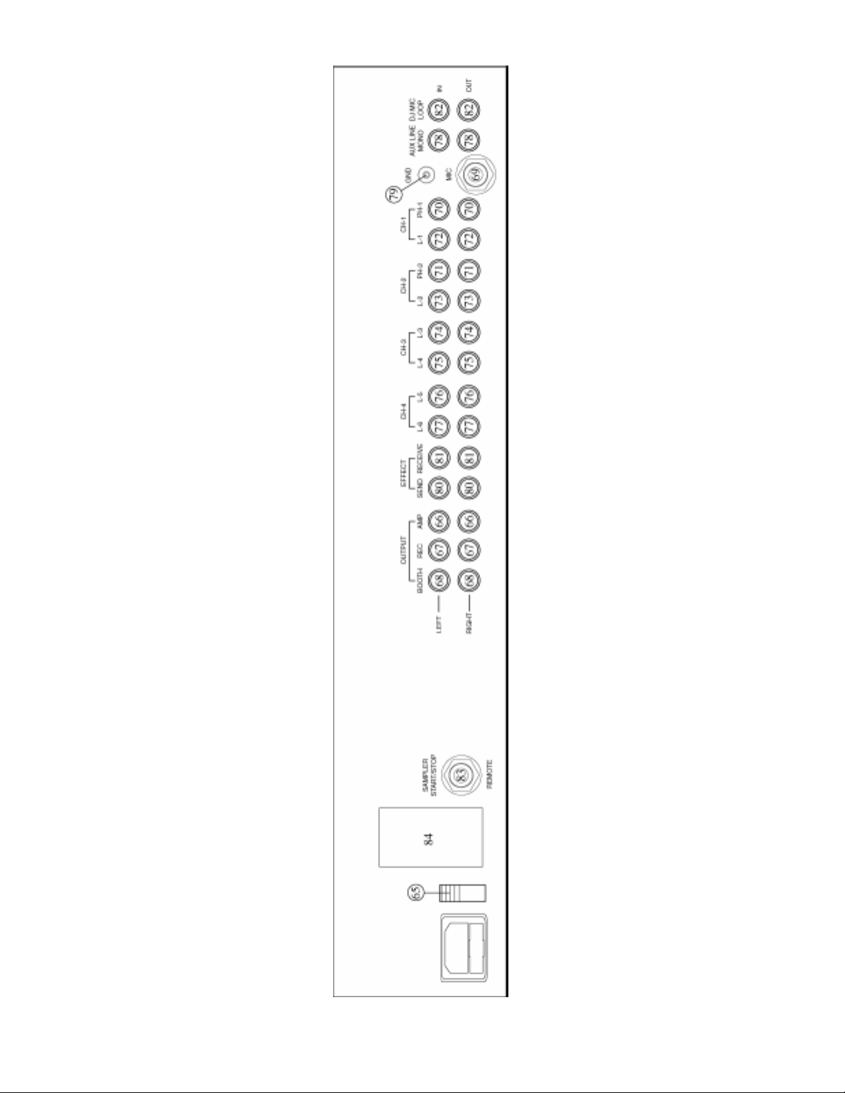
1. Before plugging in the power cord, make sure that the VOLTAGE
SELECTOR (65) switch is set to the correct voltage.
Note: This product is double insulated and not intended to be grounded.
2. Make sure that the POWER (1) switch is in the off position. The
POWER LED (2) will be off.
3. The PS-924 is supplied with 3 sets of output jacks. The OUTPUT
AMP (66) jacks are used to connect to your main amplifier. The
OUTPUT REC (67) jacks can be used to connect the mixer to the
record input of your recorder enabling you to record your mix. The
OUTPUT BOOTH (68) jacks allow you to hook up an additional
amplifier.
4. The PS-924 is equipped with 2 microphone inputs. The DJ MIC (3)
input (found on the front panel) accepts 1/4" or XLR connectors and
suitable for balanced or unbalanced microphones. The AUX MIC
(69) input (found on the rear panel) is a 1/4" jack for an unbalanced
microphone.
5. On the rear panel are 2 stereo PHONO (70, 71) inputs, 6 stereo LINE (72,
73, 74, 75, 76, 77) inputs and 1 mono AUX LINE (78) input. The stereo
phono inputs will accept only turntables with a magnetic cartridge. A
GROUND (79) screw for you to ground your turntables is located on the
rear panel. The stereo line inputs will accept any line level input such as
a CD player, a cassette player, etc.
Note: The AUX LINE (78) input is composed of 2 RCA jacks. When
connecting a mono line level source, either jack can be used. By
connecting a stereo line level device to both jacks, the input will be
combined to one mono signal.
6. Headphones can be plugged into the front panel mounted
HEADPHONE (4) jack.
7. The PS-924 comes with a front panel XLR LIGHT (5) jack. This jack
is for use with a gooseneck light like the Gemini GNL-500. NEVER
plug a microphone into this jack.
8. If you are using an off board signal enhancer , you can use the SEND
(80) output to send the signal to the device and the RECEIVE (81)
input jacks to bring the signal back in to the PS-924.
9. The PS-924 is supplied with DJ MIC LOOP (82) jacks that can be
used to add an audio enhancer such as a key controller to the mic
circuit. There must be a connection to these jacks. If no device is
being used in the DJ mic loop, then the jumper wire, (included), must
be in place.
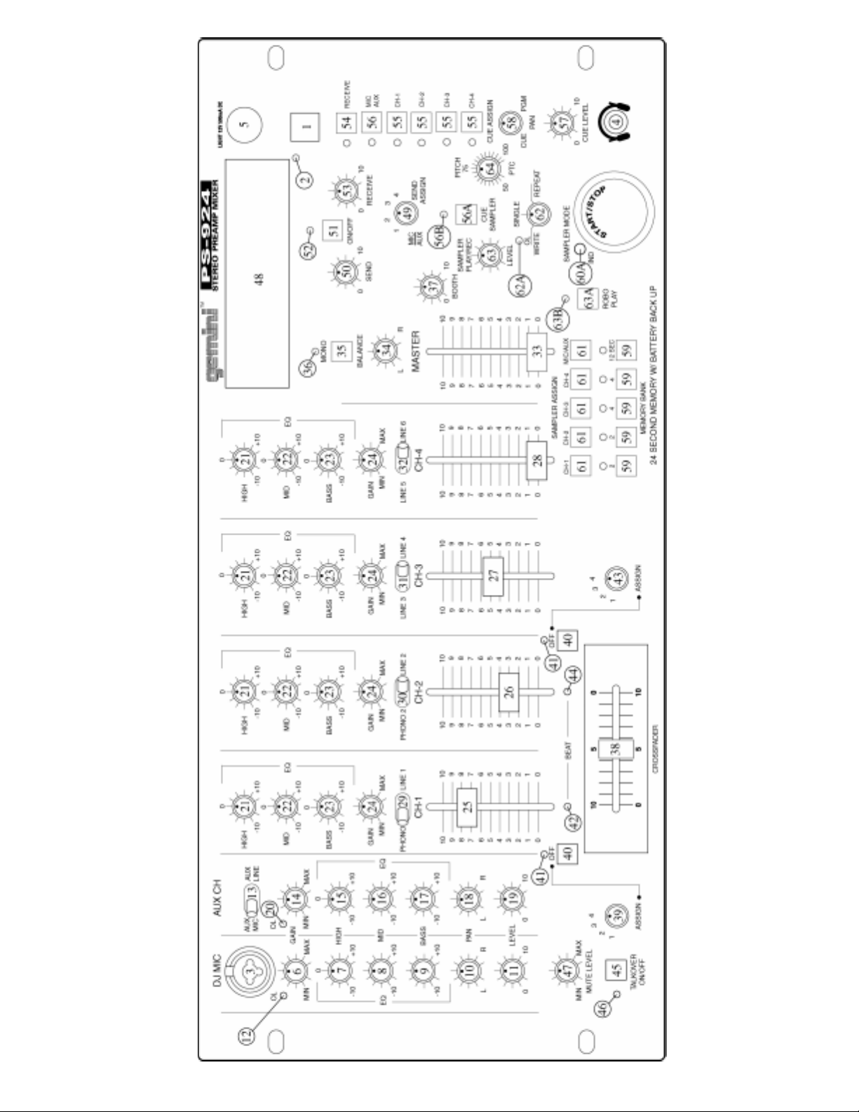
OPERATION
1. POWER ON: Once you have made all the equipment connections to
your mixer, press the POWER SWITCH (1). The power will turn on
and the POWER LED (2) will glow RED.
2. DJ MIC SECTION: The GAIN (6), TREBLE (7), MID (8), BASS (9),
PAN (10) and LEVEL (1 1) controls allow full adjustment of the DJ mic
that is plugged into the DJ MIC (3) input.
Note: The OVERLOAD LED (12) glows red when the DJ mic is being
over driven. To correct the setting, turn down the GAIN (6) control
until the LED goes off.
3. AUX CHANNEL: By using the AUX MIC/LINE (13) switch, you can
choose between an additional mic or an additional mono line input.
The GAIN (14), TREBLE (15), MID (16), BASS (17), PAN (18) and
LEVEL (19) controls fully adjust the Aux Channel input you selected
with the AUX MIC/LINE (13) switch.
Note: The OVERLOAD LED (20) glows red when the Aux Channel is
being over driven. To correct the setting, turn down the GAIN (14)
control until the LED goes off.
HINT: Like the DJ Mic, the Aux Channel is always live. Hooking up another mic or
a mono line device such as a sound effects generator or a drum machine, will allow
you to play the selected source at any time.
4. MAIN CHANNEL SECTION: T o assign an input source to a channel,
set the PHONO/LINE (29,30) and the LINE/LINE (31, 32) switches to
their appropriate positions. To make the proper adjustments to your
music, set the TREBLE (21), MID (22), BASS (23) and GAIN (24)
controls and the CHANNEL (25, 26, 27, 28) slides.
5. CROSSFADER SECTION: The CROSSFADER (38) allows the mixing
of one source into another. The PS-924 features an assignable
crossfader. The ASSIGN (39,43) switches allow you to select which
cannel will play through each side of the CROSSFADER. ASSIGN
(39) switch allows you to select channel 1, 2, 3 or 4 to play through
the left side of the CROSSFADER. ASSIGN (43) switch does the
same to the right side of the CROSSFADER. Each assign switch has
its own OFF (40) switch and OFF INDICATOR (41) LED. With the
OFF (40) switch in the off position (the OFF INDICATOR (41) glows
red), that side of the CROSSFADER (38) will be inactive.
HINT: T ry using the OFF (40) switches when you are changing the ASSIGN (39,43)
switch settings. For Example: Assume that you have a turntable hooked up to
channel 1, a tape deck hooked up to channel 2 and a CD player hooked up to
channel 3. The left side ASSIGN (39) switch is set to 1, the right side ASSIGN (43)
is set to 2, and the CROSSFADER (38) is all the way to the right. Under this set of
circumstances, channel 2 will be playing your tape deck. Now suppose you want
to change the left side ASSIGN (39) switch to # 3 so that you can use your CD
player. You must turn the left side ASSIGN (39) off by pressing the OFF (40) Switch
(the OFF INDICATOR (41) glows red). Then you can make your changes to the
setting. Reactivate the ASSIGN (39) switch by pressing the OFF (40) switch (the
OFF INDICAT OR (41) goes off). Failure to do this will result in an audio glitch when
the assign (39) switch setting is changed.
The CROSSFADER (38) in your unit is REMOV ABLE and if the need
arises can be easily replaced. Crossfader units are available in two
sizes. Part # RF-45 (which is identical to the crossfader supplied
with the PS-924) has a 45 mm travel from side to side. Also available
is part # RF-30 which has a 30 mm travel distance Just purchase
either of these crossfader units from your Gemini dealer and follow
these instructions:
Page 3
Page 5

1. Unscrew the outside FADER plate screws (B). Do not
touch the INSIDE SCREWS (C).
2. Carefully lift the fader and unplug the CABLE (D).
3. Plug the new fader into the cable and place it back in
the mixer.
4. Screw the fader to the mixer.
6. BEAT INDICA TORS: Each side of the CROSSF ADER (38) has its own
BEAT INDICATOR (42, 44). They flash at the low frequency peak
level of each assigned source, allowing you to match the beats
visually. BEAT INDICATOR (42) will reflect the beat of the source
assigned to the left side of the CROSSFADER (38) and BEAT
INDICATOR (44) will do the same for the right side.
Note: The flashing level can be fine tuned by increasing or decreasing
the gain and bass controls of the assigned channel.
7. OUTPUT CONTROL SECTION: The level of the AMP OUT (66) is
controlled by the MASTER (33) slide. The BALANCE (34) control
will allow the Amp Out signal to be balanced between the left and
right speakers. The MONO (35) switch, when depressed, (the
MONO LED (36) will glow), will make the Amp Out signal a mono
signal. The BOOTH (37) control adjusts the level of the BOOTH
OUTPUT (68).
Note: The LED DISPLAY (48) indicates the AMP OUT (66) signal
only and is not affected by the BOOTH OUTPUT (68) signal.
HINT: The booth OUTPUT is used by some DJs to run monitor speakers in their DJ
booth. You can also use it as a second ZONE or AMP output.
Note: The RECORD OUT (67) has no level control. The level is set by
the channel slides and the gain control of the selected channel. The
tonal qualities are set by the bass, treble and mid controls of that
same channel
8. TALKOVER SECTION: The purpose of the talkover section is to
allow the program playing to be muted so that the mic can be heard
above the music. When the TALKOVER ON/OFF (45) button is pushed
(the TALKOVER INDICA T OR (46) will glow), the volume of all sources
except the DJ Mic and the Aux channel are reduced. The amount of
reduction can be set between -6 dB and -36 dB by using the MUTE
LEVEL (47) control.
9. SEND AND RECEIVE SECTION: By using the SEND ASSIGN (49)
switch, you can send the selected signal to some sort of audio
enhancement device (like a digital sampler or key controller). The
level of the signal being sent can be adjusted by the SEND (50)
control. To receive the signal back into the PS-924, you must first
turn on the RCV ON (51) switch (LED (52) will light). The level of the
signal being received can be adjusted with the RECEIVE (53) control.
Note: The signal being received back into the PS-924 can be monitored
by using the headphones and by pressing the RECEIVE (54) cue
control. If the RCV ON (51) switch is in the off position (LED (52)
is off), the level of the signal can be monitored and adjusted prior to
its playing through the output. Turning the RCV ON (51) switch to
the on position connects the received signal to the output section.
HINT: The RECEIVE (81) input can be used as an additional stereo line level input
controlled by the RECEIVE (53) and activated by the RCV ON (51) switch.
10.CUE SECTION: By connecting a set of headphones to the
HEADPHONE (4) jack, you can monitor any or all of the channels.
CUE ASSIGN (55) buttons are for the channels 1 - 4 and the CUE
ASSIGN (56) button is for the Aux Mic/Line Mono channel and the DJ
Mic.
HINT: When you are using the DJ Mic and have a device connected to the DJ Mic
Loop, the signal you hear in the headphones includes the device in the loop.
Select the correct Cue assign button or buttons and their respective
LED indicators will glow. Use the HEADPHONE LEVEL (57) control
to adjust the headphone volume with out effecting the overall mix.
By rotating the CUE PGM PAN (58) control to the left you will be able
to monitor the assigned cue signal. Rotating to the right will monitor
the PGM (program) output .
SAMPLER OPERATION
GENERAL INFORMATION: The PS-924 Sampler uses Dynamic RAM
memory and a 12 bit microprocessor controller. The full bandwidth
results in true sound reproduction.
MEMORY INFORMATION: The PS-924 comes equipped with five
MEMORY BANKS (59). The two banks marked 2 & 2 are two seconds
in length, the two banks marked 4 & 4 are four seconds in length and the
bank marked 12 is twelve seconds in length. These banks are separate
and can not be linked. Y ou can store a different sample in each bank but
they must be recorded individually and they must be played one at a
time.
SAMPLE RECORDING:
1. Put the MODE SELECTOR (62) switch into the WRITE position.
2. Select the source you want to sample from by pressing the
appropriate ASSIGN BUTTON (61).
3. Select the memory bank you want to record into, by pressing the
proper MEMORY BANK (59) button.
4. Model PS-924 is equipped with a SAMPLER REC/PLAY LEVEL (63)
control. When the MODE SELECTOR (62) is in the WRITE mode, this
control acts as a Record Level Control. If the OVERLOAD INDICAT OR
(62A) is blinking, it means that the input signal you are going to sample, is
too strong and will cause he sample to be distorted. Lower the sample
signal intensity by turning the SAMPLER REC/PLA Y LEVEL (63) control
counter clockwise. If the OVERLOAD INDICAT OR (62A) is of f, turn the
SAMPLER REC/PLAY LEVEL (63) control clockwise until the
OVERLOAD INDICATOR (62A) begins to blink and then turn the
SAMPLER REC/PLAY LEVEL (63) control counter clockwise until the
OVERLOAD INDICATOR (62A) goes off.
5. Tapping the START/STOP (60) button begins the sampling process
(the SAMPLER INDICATOR (60A) will illuminate RED). Tapping the
START/STOP (60) button a second time ends the sample (the
SAMPLER INDICATOR (60A) will turn off). If you do not tap the
START/STOP (60) button a second time, the sampling process will
stop automatically after 2, 4 or 12 seconds depending on which
MEMORY BANK (59) was selected.
SAMPLE PLAYBACK:
1. Put the MODE SELECTOR (62) switch into the SINGLE or REPEA T
position.
2. Select the memory bank you wish to play by pressing the proper
MEMORY BANK (59) button.
3. When the MODE SELECTOR (62) is in the SINGLE or REPEAT
mode, the SAMPLER REC/PLAY LEVEL (63) control acts as a
Sampler Level Control.
4. Tapping the START/STOP (60) button with the MODE SELECTOR
(62) switch in the SINGLE position will cause the sampler to playback
one time (the SAMPLER INDICAT OR (60A) will illuminate GREEN).
Every push of the START/STOP (60) button will restart the sample
from the beginning. Rapid pressing of the START/STOP (60) button
will cause a stuttering effect. Once the sample has started playback
and the START/STOP (60) button is not pushed a second time, the
sample will play to the end and then stop (the SAMPLER INDICAT OR
(60A) will turn off).
5. Tapping the START/STOP (60) button with the MODE SELECTOR
(62) switch in the REPEAT position will cause the sample to
continuously play over and over (the SAMPLER INDICATOR (60A)
will illuminate GREEN). The START/STOP (60) button will act as an
on/off switch. The first push will start the sample, the second push
will stop it.
Page 4
Page 6

ROBO PLAY :
1. With the ROBO PLAY (63A) button in the OFF POSITION (the ROBO
PLAY INDICATOR (63B) will be OFF) and the MODE SELECTOR
(62) switch in either the SINGLE or REPEAT mode, pressing the
START/STOP (60) button will cause the sample to play along with
the selected source.
2. When the ROBO PLA Y (63A) button is in the ON position (the ROBO
PLA Y INDICATOR (63B) illuminates RED), starting the sampler mutes
the selected source. When the sample ends, the source automatically
turns back on.
PITCH CONTROL:
1. The PS-924 comes equipped with a sampler PITCH (64) control. To
get a perfect sample, set the control to its center position and record
the sample.
2. During playback, raising or lowering the control will raise or lower
the pitch of the sample playback. The center position will remain as
normal pitch.
HINT: You can record a sample with the PITCH (64) control in any position.
Whatever that position is will become normal sound. If you start to record a sample
with the PITCH (64) control set at minimum (this now becomes your normal pitch), by
increasing the pitch to maximum, the pitch effect will double in speed. Recording at
maximum and lowering to minimum will do exactly the opposite.
REMOTE STAR T/STOP:
1. Plug a momentary normally open foot switch with a 1/4" plug into the
REMOTE START/STOP (83) jack on the rear panel.
2. This allows you to trigger the sampling process with the foot switch
leaving your hands free to do other things.
BATTERY BACKUP: The PS-924 is equipped with battery backup to
retain samples. To activate this feature, a 9 volt battery (not included)
needs to be connected to the BATTERY HOLDER (84) located on the
rear panel. This will enable you to store samples in memory and when
the unit is unplugged, the battery backup will retain the samples for
future use. If the unit is unplugged with no battery attached, all
the samples will be lost.
LOW BATTER Y INDICA T OR: A low battery indicator is included with the
PS-924. when changing the battery, make sure the unit is plugged in and
the power is ON. Failure to adhere to this will result in lost memory. The
low battery indicator is ON when the selected memory bank LED blinks.
The LED will also blink if no battery is connected to the unit.
SPECIFICATIONS
INPUTS:
DJ Mic................................1.5mV 3Kohm balanced/unbalanced
Aux Mic................................................1.5mV 10Kohm unbalanced only
Aux Line....................................................150mV 27Kohm
DJ Loop..............................................................150mV 10Kohm
Phono................................................................3mV 47Kohm
Line...................................................................150 mV 27Kohm
Receive................................................................75mV 27Kohm
OUTPUTS:
Amp/Booth............................................0 dB 775mV 400ohm
Max...............................24V Peak to Peak
Rec.................................................................225mV 5Kohm
DJ Loop............................................................150mV 220ohm
Send...............................................................150mV 300ohm
SAMPLER:
Sampler System..............................................12 Bit Sampling
Maximum Sample Length......................................12 Seconds
Total Memory Capacity.........................................24 Seconds
GENERAL:
Bass.................................................................................+/- 12dB
Mid.....................................................................................+/- 9dB
Treble...............................................................................+/- 12dB
Gain (Mic/Aux).........................................................0 to -40dB
Gain (Chnls 1-4)...........................................................0 to -20dB
Frequency Response...............................20Hz - 20KHz +/- 2dB
Distortion........................................................................0.02%
S/N Ratio............................................................better than 80dB
Talkover Attenuation....................................................-6 to -36dB
Headphone Impedance......................................................16ohm
Power Source.....................................115/230V 50/60Hz 15W
Dimensions.......................................482mm x 240mm x 110mm
19" x 9 1/2" x 4 1/4"
Weight........................................................................11lbs (5Kg)
Page 5
Page 7

In the U.S.A., if you have any problems with this
unit, call 1-732-969-9000 for customer service. Do
not return equipment to your dealer.
Parts of the design of this product may be protected by worldwide patents.
Information in this manual is subject to change without notice and does not represent a commitment on the
part of the vendor. Gemini Sound Products Corp. shall not be liable for any loss or damage whatsoever arising
from the use of information or any error contained in this manual.
No part of this manual may be reproduced, stored in a retrieval system or transmitted, in any form or by any
means, electronic, electrical, mechanical, optical, chemical, including photocopying and recording, for any
purpose without the express written permission of Gemini Sound Products Corp..
It is recommended that all maintenance and service on the product should be carried out by Gemini Sound
Products Corp. or it’s authorized agents. Gemini Sound Products Corp. cannot accept any liability whatsoever
for any loss or damage caused by service, maintenance or repair by unauthorized personnel.
Worldwide Headquarters • 8 Germak Drive, Carteret, NJ 07008 • USA
T el (732) 969-9000 • Fax (732) 969-9090
France • G.S.L. France • 1 1, Avenue Leon Harmel, Z.I. Antony , 92160 Antony , France
Tel: + 33 (0) 1 55 59 04 70 • Fax: + 33 (0) 1 55 59 04 80
Germany • Gemini Sound Products GmbH • Ottostrasse 6, 85757 Karlsfeld, Germany
T el: 08131 - 39171-0 • Fax: 08131 - 39171-9
UK • Gemini Sound Products • Unit C4 Hazleton Industrial Estate, Waterlooville, UK P08 9JU
T el: 087 087 00880 • Fax: 087 087 00990
Spain • Gemini Sound Products S.A. • Mino, 1 12, Nave 1, 08223 Terrassa, Barcelona, Spain
T el: 01 1-34-93-736-34-00 • Fax: 01 1-34-93-736-34-01
© Gemini Sound Products Corp. 1997 All Rights Reserved
 Loading...