

Page 1
OPERATORS MANUAL
BEDIENUNGSHANDBUCH
MANUAL DEL OPERADOR
MANUEL D’INSTRUCTIONS
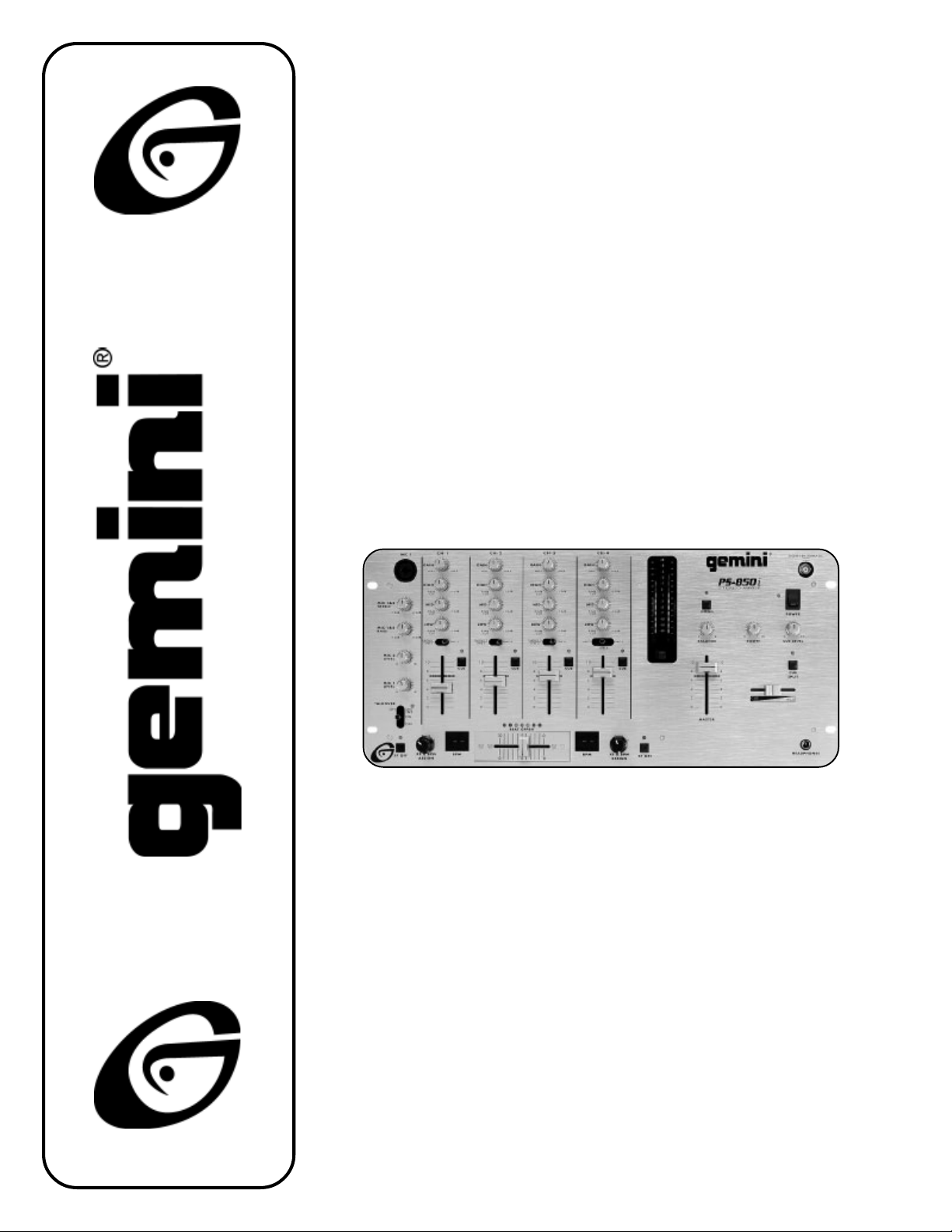
PS-850i
PROFESSIONAL STEREO PREAMP MIXER
Professionneller Stereo Vorverstärkermischpult
Mezclador-preamplificador estereofónico para el profesional
Mélangeur-préamplificateur stéréophonique pour le professionnel
Miscelatore-preamplificatore stereofonico per il professionale
Page 1
Page 2
PS-850i
36
30
31
32
27
33
34
35
26
28
29
61
25
24
63
22
18
58
19
10
9
8
8
9
10
11
16
14
11
23
23
12
59
21
17
15
57
13
20
7
1
2
3
Page 2
4
5
6
62
60
Page 3

PS-850i
Page 3
Page 4

INTRODUCTION
Congratulations on your purchase of the
Stereo PreAmp Mixer
a three year warranty, excluding crossfader and channel slides. Prior to
plugging in, we suggest you carefully read these instructions.
. This-state-of-the-art mixer is backed by
PS-850i
FEATURES
•
4 Stereo Channels
•
State-of-the-Art Cue Section
•
3 Phono/Line Convertible, 5 Line, and 3 Mic Inputs
•
BPM displays and beat offset indicators.
•
Cut Feature for Low, Mid and High for Each Channel
•
Gain, High, Mid and Low Tone Controls for Each Channel
•
Talkover
•
Loop
•
Balanced and Unbalanced Master Outputs
•
Booth and Record Outputs
•
Dual Mode Display
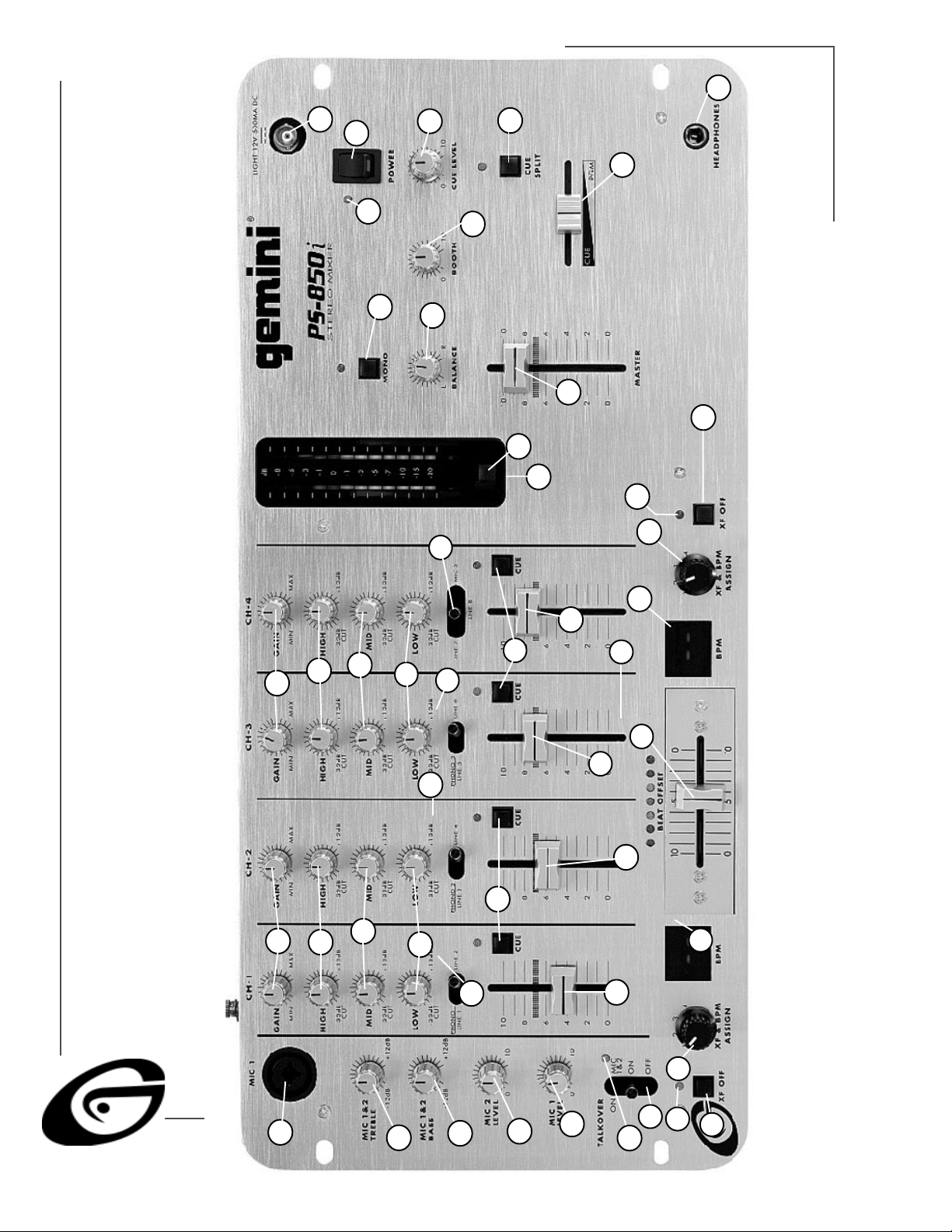
CAUTIONS
1. Read all operating instructions before using this equipment.
2. To reduce the risk of electrical shock, do not open the unit. THERE
ARE NO USER REPLACEABLE PARTS INSIDE. Please refer all unit
servicing to a qualified Sound Products service
technician.
The REC OUTPUT (41) (RCA type) jacks can be used to
connect the mixer to the record input of your recorder
•
enabling you to record your mix.
The BOOTH OUTPUT (40) (RCA type) jacks allow you to
hook up an additional amplifier.
•
4. The MIC 1 (1) input (found on the front panel) accepts XLR &1/4"
connectors. The MIC 2 (56) input and the MIC 3 (55) input (found
on the rear panel) accept 1/4" connectors. All accept balanced and
unbalanced microphones.
5. On the rear panel are three (3) stereo PHONO/LINE (47, 50, 53)
inputs and 5 stereo LINE (44, 45, 46, 49, 52) inputs.
The PHONO/LINE SWITCH (48) enables you to set the (47)
•
input to Phono or Line.
The PHONO/LINE SWITCH (51) enables you to set the (50)
•
input to Phono or Line.
The PHONO/LINE SWITCH (54) enables you to set the (53)
•
input to Phono or Line.
The phono inputs will accept only turntables with a magnetic cartridge.
6. A turntable GROUND SCREW (57) is located on the rear panel.
7. Headphones can be plugged into the front panel mounted
HEADPHONE JACK (36) .
8. The
PS-850i
jack is for a gooseneck lamp such as the
9. There are LOOP INPUTS (43) and LOOP OUTPUTS (42) located on
the rear panel. If you are using an outboard signal processor, you
can use the LOOP OUTPUTS (42) to send the signal to the device
and the LOOP INPUTS (43) to bring the signal back in to the mixer.
The unit comes with jumpers to be used with the loop inputs and
outputs. Keep the jumpers in the unit if you are not using the loop to
prevent interruptions in your music program.
features a front panel BNC LIGHT JACK (30) . This
Gemini GNL-700
.
In the USA: If you experience problems with this unit,
please call 1 (732) 969-9000 for Gemini Customer Service.
Do not attempt to return this equipment to your dealer.
3. Do not expose this unit to direct sunlight or to heat sources such
as a radiator or stove.
4. This unit should be cleaned with a damp cloth ONLY. Avoid solvents
and other cleaning detergents. Do not use spray cleaner or lubricant
on controls or switches.
5. When moving this equipment, it should be placed in its original carton
and packaging to reduce the risk of damage during transit.
6. DO NOT EXPOSE THIS UNIT TO RAIN OR MOISTURE.
CONNECTIONS
1. Before plugging in the power cord, make sure that the VOLTAGE
SELECTOR (37) switch is set to the correct voltage.
NOTE: This product is double insulated
)
2. Make sure that the POWER (31) switch is in the OFF position.
3. The
and is not intended to be grounded.
The POWER LED (32) will be OFF.
PS-850i
The XLR BALANCED OUTPUT (38) jacks are used to
•
connect to your main amplifier using standard XLR cables.
We recommend using balanced amp outputs if the cables to
your amp are 10 feet or more. XLR BALANCED OUTPUTS
have three separate conductors, two of which are signal
(positive and negative) and one shield (ground). Pin 1 is
ground (shield). Pin 2 is signal hot (positive). Pin 3 is signal
cold (negative).
•
The MAIN OUTPUT (39) (RCA type) jacks are unbalanced
and used to connect to your main amplifier.
is supplied with four (4) sets of output jacks.
THE GROUND LIFT SWITCH
epending on your system configuration, applying the ground
sometimes creates a quieter signal path. Sometimes “lifting” the
D
ground eliminates loops and hum to create a quieter signal path.
1. Listen to the system with the unit ON, without music, and with the
ground “applied.” GROUND LIFT SWITCH (58) should be to the left.
2. Turn power OFF before moving the GROUND LIFT SWITCH.
3. Now, “lift” the ground by moving the GROUND LIFT SWITCH to the
right. Turn the power back ON and listen to determine which position
provides a signal free of background noise and hum.
Note: Keep GROUND LIFT in the ground “applied” or left
position if noise level remains the same in either position.
CAUTION: DO NOT TERMINATE THE AC GROUND ON THE POWER
KK
K
KK
CABLE. TERMINATION OF THE AC GROUND CAN BE HAZARDOUS.
OPERATION
1. POWER ON: Once you have made all the equipment connections
to your mixer, press the POWER SWITCH (31). The power will
turn on and the POWER LED (32) will “glow” RED.
2. CHANNEL 1: The GAIN (8), HIGH (9), MID (10), and LOW (11)
controls allow you to fully adjust the selected source. Switch (12)
allows you to select the PHONO 1/LINE 1 (53) or the LINE 2 (52)
input. CHANNEL SLIDE (13) controls the input level of this channel.
3. CHANNEL 2: The GAIN (8), HIGH (9), MID (10), and LOW (11)
controls allow you to fully adjust the selected source. Switch (14)
allows you to select the PHONO 2/LINE 3 (50) or the LINE 4 (49)
input. CHANNEL SLIDE (15) controls the input level of this channel.
4. CHANNEL 3: The GAIN (8), HIGH (9), MID (10), and LOW (11)
Page 4
Page 5

controls allow you to fully adjust the selected source. Switch (16)
6
6
6
6
3
3
12
12
12
allows you to select the PHONO 3/LINE 5 (47) or the LINE 6 (46)
input. CHANNEL SLIDE (17) controls the input level of this channel.
5. CHANNEL 4: The GAIN (8), HIGH (9), MID (10), and LOW (11)
controls allow you to fully adjust the selected source. Switch (18)
allows you to select the LINE 7 (45), LINE 8 (44) or the MIC 3 (55)
input. CHANNEL SLIDE (19) controls the input level of this channel.
PLEASE NOTE: There is Low, Mid and High equalization for
each channel with an extremely wide range of adjustment.
SUGGESTION: You can use the Cut Features on each channel
to remove Low, Mid and/or High range to create special effects.
he Crossfader in your unit is removable, and should the
need arise, can easily be replaced by following these
T
instructions. Note: Gemini replacement Crossfaders are
available in three varieties: the RG-45 PRO (RAIL GLIDE™) Dual-Rail
Crossfader; the RF-45, which has a 45mm travel from side-to-side;
and the PSF-45, which features a special “curve” designed for scratch
mixing.
1. Unscrew the outside
FADER PLATE SCREWS (B).
- Do not touch INSIDE SCREWS (C).
2. Carefully remove old Cross fader and unplug CABLE (D).
3. Plug new Crossfader into
CABLE (D) and place back into mixer.
4. Screw Crossfader to mixer with
FADER PLATE SCREWS (B).
✦
Your Gemini mixer comes with an
GLIDE™) DUAL-RAIL CROSSFADER
Crossfaders have internal dual stainless steel rails that allow the
slider to ride smoothly and accurately from end to end.
6. CROSSFADER SECTION: The CROSSFADER (21) allows the mixing
of one source into another. The
crossfader. The ASSIGN (20, 22) switches allow you to select
which channel will play through each side of the crossfader. The
ASSIGN (20) switch has 4 settings (1, 2, 3 or 4) and allows you to
select channel 1, 2, 3 or 4 to play through the left side of the
crossfader. The ASSIGN (22) switch has 4 settings (1, 2, 3 or 4)
and allows you to select channel 1, 2, 3 or 4 to play through the
right side of the crossfader. There are two OFF (60, 61) buttons for
the crossfader. When the OFF (60) button is pressed, the left side
of the crossfader will be inactive and the OFF LED (62) will light.
When the OFF (61) button is pressed, the right side of the
crossfader will be inactive and the OFF LED (63) will light. Using the
OFF button, be sure to deactivate the crossfader before changing
the ASSIGN setting. This will avoid any click or popping sound in
your signal while you are changing the assign setting.
7. LOOP: Removing the jumpers from the LOOP OUTPUT (42) and
INPUT (43) jacks will activate the loop. Any device connected to
the LOOP OUTPUT (42) and INPUT (43) jacks will be inserted into
the signal path.
HINT: BOOTH OUTPUT (40) is used by some DJs to run
Ú
monitor speakers in the DJ Booth. You can also use it as a
second ZONE or AMP output.
NOTE: The RECORD OUT (41) has no level control. The
level is set by the channel slides and the gain controls of the
selected channel. Tonal qualities are set by the LOW, MID and
HIGH controls of that same channel.
234567890123456789012
234567890123456789012
RG-45 PRO (RAIL
PS-850i
2345
2345
2345
2345
D
. Rail Glide™
features an assignable
8. OUTPUT CONTROL: The level of the AMP OUT (38, 39) is
controlled by the MASTER (29) slide and BALANCE (28) control.
Activating the MONO (27) button (the mono LED will light) makes the
overall output mono. The BOOTH (26) control adjusts the level of the
BOOTH OUTPUT (40).
9. TALKOVER: The purpose of the talkover is to allow the program
playing to be muted so that the mic may be heard above the music.
The MIC/TALKOVER SWITCH (7) controls MIC 1 and MIC 2 and
has three settings.
•
When MIC/TALKOVER (7) is in the BOTTOM position,
MIC and TALKOVER are OFF.
•
When MIC/TALKOVER (7) is in the CENTER position, MIC is
ON. MIC INDICATOR (6) glows. TALKOVER is OFF.
•
When MIC/TALKOVER SWITCH (7) is in the TOP position,
MIC and TALKOVER are ON and the volume of all sources
except MIC input is lowered by 16 dB. MIC 1 LEVEL (5)
controls the level of MIC 1. MIC 2 LEVEL (4) controls the
level of MIC 2.
10.CUE: By connecting a set of headphones to the HEADPHONE JACK
(36), you can monitor any or all of the channels. Press the CUE
ASSIGN (23) buttons for channels 1 - 4 to select the channel or
channels to be monitored and their respective LED indicators will
glow.
Use CUE LEVEL (33) control to adjust cue volume without affecting
the overall mix. By moving the CUE PGM PAN (35) control to the left
you will be able to monitor the assigned cue signal. Moving the
control to the right will monitor the PGM (program) output.
Use the CUE SPLIT (34) button to split the signals from cue and `
program so that cue will be heard in one earphone and program
in the other.
11. DISPLAY: The peak hold, dual function DISPLAY (24) indicates
either the MASTER (38, 39) output left and right levels OR the
selected cue and program (premaster output) levels. You can
choose the option you want by pressing the DISPLAY (25) button.
Ú
12.The TREBLE (2) and BASS (3) controls allow you to adjust
13.BPM DISPLAY: There are BPM DISPLAYS (57, 58) for the two
14.The BEAT OFFSET INDICATORS (59) light when the tracks of the
Ú
SUGGESTION: You can use the BPM DISPLAYS to determine which
tracks have similar or the same Beats Per Minute. When mixing two
NOTE: When the DISPLAY is in the cue/program mode you
can increase or decrease the signal to match the other
channel’s signal simply by adjusting GAIN (8).
the tone of MIC 1 and MIC 2.
channels assigned to each side of the CROSSFADER (21). They
update approximately every 2.5 seconds and digitally display the
Beats Per Minute allowing you to match the beats visually. BPM
DISPLAY (57) reflects the Beats Per Minute of the channel assigned
to the left side of the CROSSFADER, and BPM DISPLAY (58)
reflects the Beats Per Minute of the channel assigned to right the
side of the CROSSFADER.
NOTE: A [- -] reading will appear on the BPM DISPLAY if
the track has unclear beats. The [- -] reading will also
appear if there is no signal present.
two channels assigned to the crossfader are within 11 BPMs of
each other and display how aligned the beats of the two channels
are. When the YELLOW LEDs light, the beats are almost aligned.
When the GREEN LED lights, the beats are aligned perfectly.
NOTE: If the difference between the two channel’s
beats exceed 11 BPM, the BEAT OFFSET INDICATORS
will not light.
Page 5
Page 6

tracks with similar Beats Per Minute, you can use one source’s pitch
control to align the Beats Per Minute with the other source’s BPM. The
BPM DISPLAY and the BEAT OFFSET INDICATORS update every 2.5
seconds and will reflect the change in BPM and indicate when the
beats are aligned.
NOTE: Beat mixing is a skill that requires practice. Not every
Ú
track has a strong beat, and beat mixing works best with
tracks with tracks with clear and strong beats.
SPECIFICATIONS
INPUTS:
Phono @ 1kHz.......................................................................2mV 47 kΩ
Line...............................................................................100 mV 10 kΩ
MIC 1 , MIC 2 & MIC 3....................................................1.5mV 2 KΩ Balanced
OUTPUTS:
Main/Aux.......................................................................0 dB 1V 400 kΩ
Max...............................................................................20V Peak-to-Peak
Rec..................................................................................225mV 5 kΩ
GENERAL:
Low (Channels 1-4).............................................................+ 12dB/- 32 dB
Mid (Channels 1-4)...............................................................+ 12dB/- 32 dB
High (Channels 1-4).............................................................+ 12dB/- 32 dB
Gain (Channels 1-4).......................................................................0 to -20dB
Bass (MIC1 , MIC2).......................................................................± 12dB
Treble (MIC1 , MIC2).......................................................................± 12dB
Frequency Response............................................20Hz - 20kHz +/- 2dB
Distortion................................................................................less than 0.02%
S/N Ratio..........................................................................better than 80dB
Talkover Attenuation........................................................................16dB
Power Source...................................................115/230V 50/60Hz 20W
Dimensions....................................................................19”W x 4”H x 9”D
Weight........................................................................................10 lbs
Page 6
 Loading...