

Page 1
OPERATIONS MANUAL
Bedienungsanleltung
Manual de funcionamiento
Manual de fonctionnement
Manual del utente
PS-626 PRO2
PROFESSIONAL STEREO PREAMP MIXER
Professionneller Stereo Vorverstärkermischpult
Mezclador-preamplificador estereofónico para el profesional
Mélangeur-préamplificateur stéréophonique pour le professionnel
Miscelatore-preamplificatore stereofonico per il professionale
For assistance and information in the
U.S.A. call toll free 1-800-476-8633
Multi Language Instructions
English............................................................................Page 3
Deutsch..........................................................................Page 5
Español...........................................................................Page 7
Francais..........................................................................Page 9
Italiano.............................................................................Page 11
Page 2
26
28
19
3
6
7
88
9
10
13
27
66
7
9
11
12
15
5
2
1
7
8
9
21
21
21
16
17
18
20
29
22
14
25
23 24
Page 1
4
Page 3
Page 2
30
GROUND LIFT
41
LIFT
GND
37
LINE 1
PHONO 1
35
L
R
38
38
MASTER
39
39
BOOTH
OUTPUT
40
40
REC
34
34
PHONO 3
CH-3
33
33
LINE 3 PHONO 2
32
32
CH-2
31
31
LINE 2
36
36
PHONO 2
LINE 1
CH-1
Page 4

Introduction
Congratulations on purchasing a Gemini Platinum Series model PS-626
PRO2 mixer. This state of the art mixer is backed by a three year
warranty, excluding crossfader and channel slides. Prior to use, we
suggest that you carefully read all the instructions.
Features
• Cut Feature for Low, Mid and High of each channel
• 3 Stereo channels (3 Phono, 3 Line and 1 Mic)
• Combo XLR or 1/4" DJ Mic jack
• Low, Mid, High and Gain controls on each channel
• Beat indicators
• 12 volt BNC light jack
• Master, Booth and Record outputs
• Dual mode display (Left & Right output or Channel 2 and Channel 3)
• Push button cueing with Cue/Program pan control
Cautions
1. All operating instructions should be read before using this
equipment.
2. To reduce the risk of electrical shock, do not open the unit. There
are NO USER REPLACEABLE P ARTS INSIDE. Please refer servicing
to a qualified service technician.
In the U.S.A., if you have any problems with this unit,
call 1-732-969-9000 for customer service. Do not return
equipment to your dealer.
3. Do not expose this unit to direct sunlight or to a heat source such as
a radiator or stove.
4. This unit should be cleaned only with a damp cloth. Avoid solvents
or other cleaning detergents.
5. When moving this equipment, it should be placed in its original carton
and packaging. This will reduce the risk of damage during transit.
6. DO NOT EXPOSE THIS UNIT TO RAIN OR MOISTURE.
7. DO NOT USE ANY SPRAY CLEANER OR LUBRICANT ON ANY
CONTROLS OR SWITCHES.
Connections
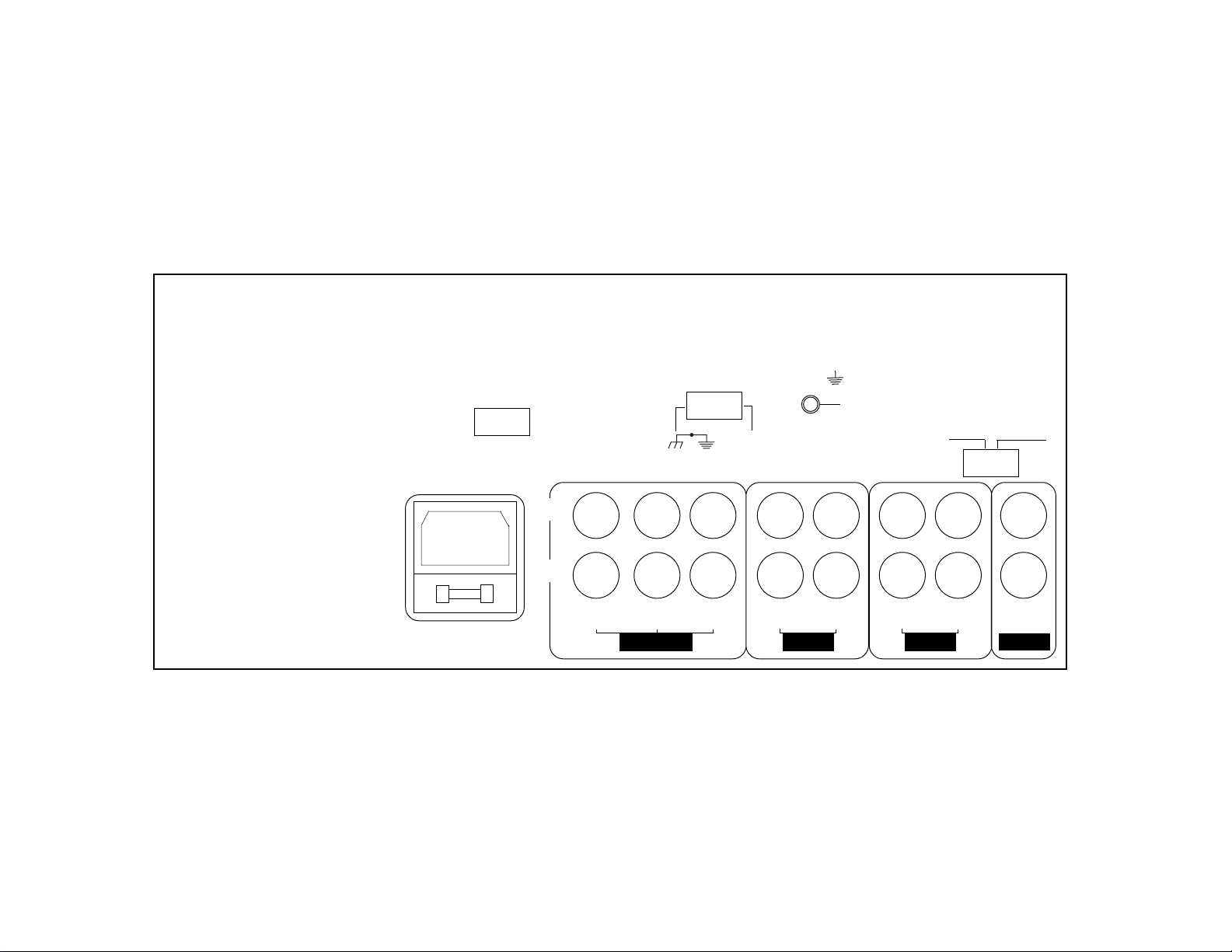
1. Before plugging in the power cord, make sure that the VOLTAGE
SELECTOR (30) switch is set to the correct voltage.
NOTE: This product is double insulated and not intended
to be grounded.
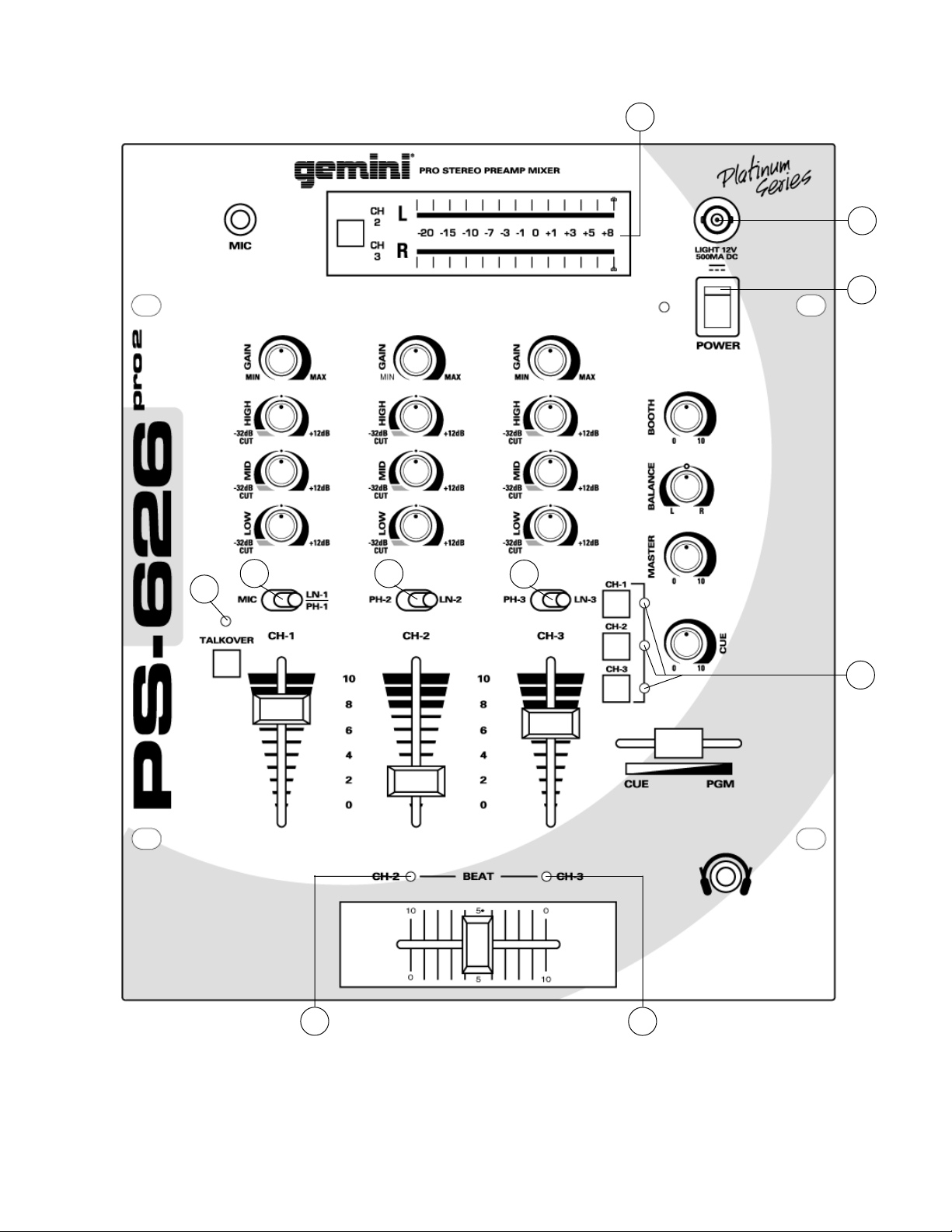
2. Make sure that the POWER (1) switch is in the off position. The
POWER LED (2) will be off.
3. The PS-626 PRO2 is supplied with 3 sets of output jacks. The
OUTPUT AMP (38) jacks are used to connect to your main amplifier.
The OUTPUT REC (40) jacks can be used to connect the mixer to
the record input of your recorder enabling you to record your mix.
The OUTPUT BOOTH (39) jacks allow you to hook up an additional
amplifier.
4. The DJ MIC (3) input (found on the front panel) accepts a 1/4"
connector and accepts only unbalanced microphones.
5. On the rear panel are 2 stereo PHONO (32, 34) inputs, 2 stereo
LINE (31, 33) inputs and 1 stereo PHONO/LINE (36) input. The
PHONO/LINE (35) switch enables you to set the (36) input to Phono
or Line. The phono inputs will accept only turntables with a magnetic
cartridge. A GROUND (37) screw for you to ground your turntables
is located on the rear panel. The stereo line inputs will accept any
line level input such as a CD player, a cassette player, etc.
6. Headphones can be plugged into the front panel mounted
HEADPHONE (4) jack.
7. The PS-626 PRO2 comes with a front panel BNC LIGHT (5) jack.
This jack is for use with a gooseneck light like the Gemini GNL-700.
Using the Ground Lift Switch
Depending on your system configuration, sometimes applying the
ground will create a quieter signal path. Sometimes lifting the ground
can eliminate ground loops and hum to create a quieter signal path.
1. With the mixer on, listen to the system in idle mode (no signal
present) with the ground applied (the GROUND LIFT SWITCH (41)
in the left position).
2. Then turn the power off before moving the GROUND LIFT
SWITCH (41). Lift the ground by moving the GROUND LIFT SWITCH
to the right, turn the power back on and listen to determine which
position will provide a signal devoid of background noise and hum.
Keep the GROUND LIFT SWITCH in the ground position if the noise
level remains the same in either position.
CAUTION: DO NOT TERMINATE THE AC GROUND ON THE POWER
MIXER IN ANY WA Y . TERMINA TION OF THE AC GROUND CAN BE
HAZARDOUS.
Operation
1. POWER ON: Once you have made all the equipment connections to
your mixer, press the POWER SWITCH (1). The power will turn on
and the POWER LED (2) will glow RED.
2. CHANNEL 1: The GAIN (6), HIGH (7), MID (8), and LOW (9),
controls allows you to fully adjust the selected source. Switch #
(10) allows you to select either the mic or the PHONO/LINE (36)
input. The CHANNEL (13) slide controls the output level of this
channel.
3. MAIN CHANNEL SECTION: T o assign an input source to a channel,
first set the PHONO/LINE (11,12) switches to their appropriate
positions. To make the proper adjustments to your music, set the
GAIN (6), HIGH (7), MID (8) and LOW (9) controls and position the
CHANNEL (14, 15) slide.
NOTE: There is Low, Mid and High equalization for each
channel with an extremely wide range of adjustment
giving you a smoother mix.
SUGGESTION: You can use the Cut Features on each channel to
remove Low, Mid and/or High to create special effects.
4. CROSSFADER SECTION: The CROSSFADER (25) allows the mixing
of one source into another. The left side of the CROSSFADER (25) is
channel 2 and the right side is channel 3. The CROSSFADER (25) in
your unit is removable and if the need arises can be easily replaced.
Crossfader units are available in three varieties. Part # RF-45
(which is identical to the crossfader supplied with the mixer) has a
45 mm travel from side to side. Part # RF-30 is available with a 30
mm travel distance. Also available is the PSF-45 with a special
curve designed for scratch mixing. Just purchase one of these
crossfader units from your Gemini dealer and follow these
instructions:
Page 3
Page 5

1. Unscrew the outside FADER PLA TE SCREWS (B). Do not
touch the INSIDE SCREWS (C).
2. Carefully lift the fader and unplug the CABLE (D).
3. Plug the new fader into the cable and place it back in the
mixer.
4. Screw the fader to the mixer.
5. BEAT INDICATORS: Each side of the CROSSF ADER (25) has its own
BEAT INDICATOR (23, 24). They flash at the low frequency peak
level allowing you to match the beats visually. BEAT INDICATOR
(23) will reflect the beat of the left side of the CROSSFADER (25)
and BEAT INDICATOR (24) will do the same for the right side.
6. OUTPUT CONTROL SECTION: The level of the AMP OUT (38) is
controlled by the MASTER (18) control. The BALANCE (17) control
will allow the Amp Out signal to be balanced between the left and
right speakers. The BOOTH (16) control adjusts the level of the
BOOTH OUTPUT (39). HINT : The booth OUTPUT is used by some
DJs to run monitor speakers in their DJ booth. You can also use it as
a second ZONE or AMP output.
NOTE: The RECORD OUT (40) has no level control.
The level is set by the channel slides and the gain
controls of the selected channel. The tonal qualities are
set by the bass, treble and mid controls of that same
channel.
7. TALKOVER SECTION: The purpose of the talkover section is to allow
the program playing to be muted so that the mic can be heard above
the music. When the TALKOVER (19) button is pushed, the
TALKOVER INDICATOR (28) will glow and the volume of all
sources except the Mic or whatever is connected to the PHONO/
LINE (36) input are reduced by -16 dB.
8. CUE SECTION: By connecting a set of headphones to the
HEADPHONE (4) jack, you can monitor any or all of the channels.
Select the correct CUE (21) button or buttons and their respective
CUE LED (29) indicators will glow. Use the CUE LEVEL (20) control
to adjust the headphone volume without effecting the overall mix. By
sliding the CUE PGM PAN (22) control to the left you will be able to
monitor the assigned cue signal. Sliding to the right will monitor the
PGM (program) output.
9. DISPLAY: The peak hold, dual function DISPLAY (26) indicates either
the MASTER (38) output left and right levels or the channel 2 and
channel 3 levels. You can choose the option you want by pressing
the DISPLAY (27) button.
NOTE: When the DISPLAY (27) is in the channel 2/
channel 3 display mode, by adjusting the individual
channel gain and tone controls, you can increase or
decrease the signal to match the other channels signal.
The channel slides and crossfader have no effect on the
display readings.
Specifications
INPUTS:
DJ Mic....................................................1.5mV 2Kohm unbalanced
Phono.........................................................................3mV 47Kohm
Line.......................................................................150 mV 27Kohm
OUTPUTS:
Amp/Booth......................................................0 dB 775mV 400ohm
Max..............................24V Peak to Peak
Rec...........................................................................225mV 5Kohm
GENERAL:
Bass...........................................................................+ 12 / -32dB
Mid............................................................................+ 12 / -32dB
Treble..........................................................................+ 12 / -32dB
Gain (Mic)........................................................................0 to -40dB
Gain (Chnls 1-3)..............................................................0 to -20dB
Frequency Response....................................20Hz - 20KHz +/- 2dB
Distortion................................................................................0.02%
S/N Ratio...............................................................better than 80dB
Talkover Attenuation..............................................................-16dB
Headphone Impedance.........................................................16ohm
Power Source.............................................115/230V 50/60Hz 15W
Dimensions...........................................254mm x 305mm x 112mm
10" x 12" x 4 7/16"
Weight........................................................................6.5 lbs (3 Kg)
Page 4
Page 6

Einführung
Wir gratulieren Ihnen zum Kauf eines Mischpults Modell
PS-626 PRO2, Gemini Platinum Serie. Dieses moderne Mischpult enthält
dreijährige Garantie, ausscheließlich crossfader und Kanalschieber.
Vor dem Gebrauch empfehlen wir, alle Anweisungen aufmerksam zu
lesen.
Eigenschaften
• CUT Funktion (Entfernungsfunktion)
• 3 Stereo-Kanäle (3 Phono, 3 Leitungen und 1 Mikrophon)
• Kombination-XLR- oder 1/4" DJ-Mikrophon-Anschluß
• Steuerungen für Tiefton, Mitte, Hochton und Verstärkungsfaktor für
jeden Kanal
• Taktanzeigen
• Anschluß für eine 12-Volt BNC-Lampe
• Ausgänge für Master, Kabine und Aufzeichnen
• Doppelter Displaymodus (Ausgabe links und rechts oder Kanal 2
und Kanal 3)
• Merkvorgang per Druckknopf mit Merk-/Programmnachführsteuerung
Vorsichtsmaßnahmen
1. Die Bedienungsanleitungen sind ganz durchzulesen, bevor dieses
Gerät in Betrieb genommen wird.
2. Um die Gefahr eines Elektroschocks zu verringern, darf das Gerät
nicht geöffnet werden. ES BEFINDEN SICH KEINE VOM ANWENDER
ZU WARTENDEN TEILE IM GEHÄUSE. Wartung ist von einem
qualifizierten Kundendiensttechniker vorzunehmen.
3. Diese Einheit ist nicht direktem Sonnenlicht oder einer Wärmequelle
wie z.B. einem Heizungselement oder einem Ofen auszusetzen.
4. Diese Einheit soll nur mit einem feuchten Tuch gereinigt werden.
Lösemittel und andere Reinigungsmittel vermeiden.
5. Zum Transport ist dieses Gerät in den ursprünglichen
Versandkarton mit dazugehöriger Verpackung zu verpacken.
Dadurch wird das Risiko der Beschädigung bei Transport verringert.
6. DIESE EINHEIT DARF NICHT REGEN ODER FEUCHTIGKEIT
AUSGESETZT WERDEN.
7. AN DEN STEUERVORRICHTUNGEN UND SCHALTERN DÜRFEN
KEINE SPRA YREINIGER ODER -SCHMIERSTOFFE VERWENDET
WERDEN.
Anschlüsse
1. Bevor das Netzkabel eingesteckt wird, ist sicherzustellen, daß der
Schalter VOLTAGE SELECTOR (30) (Spannungswahl) auf die
richtige Spannung gestellt ist.
HINWEIS: Dieses Produkt ist doppelt isoliert und darf
nicht geerdet werden.
2. Sicherstellen, daß sich der Netzschalter POWER (1) in der AusStellung befindet. Die Leuchtdiode POWER LED (2) ist aus.
3. Beim Mischpult PS-626 PRO2 sind 3 Sätze von
Ausgangsanschlüssen vorgesehen. Die Anschlüsse OUTPUT AMP
(38) (Verkstärkerausgang) dienen zum Anschließen des
Hauptverstärkers. Die Anschlüsse OUTPUT REC (40)
(Aufzeichungsausgang) können dazu verwendet werden, das
Mischpult an den Aufzeichnungseingang des Rekorders
anzuschließen, um die Mischung aufzuzeichnen. Die Anschlüsse
OUTPUT BOOTH (39) (Kabinenausgang) erlauben das Anschließen
eines weiteren Verstärkers.
4. Der Eingang DJ MIC (3) (DJ-Mikrophon) (an der vorderen
Schalttafel) nimmt Anschlüsse mit Durchmesser von 0,38 mm (1/4"),
und balancierte und unbalancierte Mikrophone auf.
5. Auf der hinteren Schalttafel befinden sich 2 Stereo-Eingänge
PHONO (32, 34), 2 Stereo-Eingänge LINE (31, 33) (Leitung) und ein
Stereo-Eingang PHONO/LINE (36) (Phono/Leitung). Der Schalter
PHONO/LINE (35) erlaubt Einstellen des Eingangs auf Phono oder
Leitung. Die Phono-Eingänge nehmen nur Plattenteller mit einem
magnetischen T onabnehmer an. Eine Schraube GROUND (37)
(Erdung) zum Erden der Plattenteller befindet sich auf der hinteren
Schalttafel. Die Stereo-Leitungs-Eingänge nehmen jede Art
ausgeregelte Eingabe wie z.B. einen CD-Spieler, einen
Kassettenspieler usw. an.
6. Kopfhörer können in den Anschluß HEADPHONE (4) (Kopfhörer)
auf der vorderen Schalttafel eingesteckt werden.
7. Das Mischpult PS-626 PRO2 hat einen Anschluß BNC LIGHT (5)
(BNC-lampe) auf der vorderen Schalttafel. Dieser Anschluß ist für
eine flexible Lampe wie z.B. eine Gemini GNL-700 bestimmt.
Benutzung des Masse-Trennschalters
Abhängig von Ihrer Systemkonfiguration, wenn man hin und wieder
Masse anlegt, kann man damit einen ruhigeren Signalpfad schaffen.
Wenn man hin und wieder die Masse trennt, kann man dadurch
Massekreise und Brummen eliminieren, um einen ruhigeren Signalpfad
schaffen.
1. Wenn das Mischpult eingeschaltet ist, das System im Ruhemodus
(ohne Signal) bei angelegter Masse abhorchen (der Masse-
Trennschalter - GROUND LIFT SWITCH (41) ist nach links
geschaltet).
2. Dann den Leistungsschalter ausschalten bevor der Masse-
Trennschalter - GROUND LIFT SWITCH (41) betätigt wird. Den
Masse-Trennschalter nach rechts legen, die Leistung wieder
einschalten und horchen, um zu bestimmen, welche Position ein
Signal ohne Grundgeräusch und Brummen erzeugt. Den MasseTrennschalter in Masseposition halten, falls der Geräuschpegel in
beiden Position unverändert bleibt.
VORSICHT : DIE MASSE IN KEINER WEISE AM MISCHPULT
ABSCHLIESSEN. DER ENDABSCHLUSS DER MASSE KANN MIT
GEFAHREN VERBUNDEN SEIN.
Bedienung
1. NETZSTROM AN: Nachdem alle Geräteanschlüsse an das Mischpult
vorgenommen wurden, den Netzschalter POWER SWITCH (1)
drücken. Der Netzstrom wird eingeschaltet und die POWER LED (2)
leuchtet ROT .
2. KANAL 1: Die Steuervorrichtungen GAIN (6) (Verstärkungsfaktor),
HIGH (7) (Hochton), MID (8) (Mitte) und LOW (9) (Tiefton)erlauben
vollständige Einstellung der ausgewählten Quelle. Der Schalter #
(10) erlaubt die Auswahl entweder des Eingangs Mikrophon oder
des Eingangs PHONO/LINE (36) (Phono/Leitung). Der Schieber
CHANNEL (13) (Kanal) steuert den Ausgangspegel dieses Kanals.
3. HAUPTKANALTEIL: Um eine Eingabequelle einem Kanal zuzuweisen,
erst die Schalter PHONO/LINE (11,12) (Phono/Leitung) in die
entsprechende Stellung bringen. Zur richtigen Einstellung der Musik
dienen die Steuervorrichtungen GAIN (6) (Verstärkungsfaktor),
HIGH (7) (Hochton), MID (8) (Mitte) und HIGH (9) (Tiefton) sowie die
Schieber CHANNEL (14, 15) (Kanal).
HINWEIS: Für jeden Kanal gibt es niedrige (Low),
mittlere (Mid) und hohe (High) Entzerrung mit einem äu
erst breiten Regulierbereich, welches eine
gleichförmigere Mischung bietet.
Page 5
Page 7

RATSCHLAG: Sie können die CUT Funktion eine jeden Kanals
benutzen, um Low, Mid und/oder High zu entfernen um
dadurch Spezialeffekte zu erziehlen.
4. ÜBERBLENDERTEIL: Der ÜBERBLENDER (25) erlaubt Mischen einer
Quelle in eine andere. Die linke Seite des ÜBERBLENDERS (25) ist
Kanal 2, die rechte Seite ist Kanal 3. Der ÜBERBLENDER (25) dieses
Geräts ist ENTFERNBAR und kann leicht ersetzt werden, falls sich
diese Notwendigkeit ergibt. Überblender sind in drei Größen
verfügbar. Teile-Nr. RF-45 (die mit dem Überblender Ihres Geräts
identisch ist) hat eine Seitenverschiebbarkeit von 45 mm. Gleichfalls
ist Teile-Nr. 30 mit einer Verschiebbarkeit von 30 mm verfügbar.
Ebenfalls ist T eile-Nr. PSF-45 mit einer Spezialkrümmung für
Raspelmischen verfügbar. Sie können einen dieser Überblender bei
Ihrem Gemini-Händler beziehen und diese Anweisungen befolgen.
1. Die AUSSEREN UBERBLENDERPLATTEN- SCHRAUBEN
(B) ausschrauben. Die INNEREN SCHRAUBEN (C) nicht
berühren.
2. Sorgfältig den Überblender herausheben und das KABEL
(D) abnehmen.
3. Den neuen Überblender in das Kabel einstecken und
wieder in das Mischpult einsetzen.
4. Den Überblender in das Mischpult einschrauben.
5. TAKT ANZEIGEN: Jede Seite des ÜBERBLENDERS (25) ist mit einer
eigenen Taktanzeige BEAT INDICATOR (23, 24) ausgerüstet. Diese
leuchten beim Spitzenpegel der niedrigen Frequenz der
zugewiesenen Quelle auf und erlauben visuellen Abgleich der Takte.
Die TAKTANZEIGE (23) gibt den T akt der Quelle, die der linken Seite
des ÜBERBLENDERS (25) zugewiesen ist, an; die TAKTANZEIGE
(24) erfüllt dieselbe Funktion für die rechte Seite.
6. AUSGANGSSTEUERUNGSTEIL: Der Pegel des AMP OUT (38)
(Verstärkerausgang) wird mittels der Steuervorrichtung MASTER
(18) gesteuert. Die Steuervorrichtung BALANCE (17) (Ausgleich)
erlaubt einen Ausgleich des Verstärkerausgangssignals zwischen
dem linken und dem rechten Lautsprecher. Die Steuervorrichtung
BOOTH (16) (Kabine) stellt den Pegel des Kabinenausgangs BOOTH
OUTPUT (39) ein. Hinweis: Manche DJs benutzen den
Kabinenausgang, um Monitorlautsprecher in der Kabine laufen zu
lassen. Er kann auch als zweite Zone oder Verstärkerausgang
benutzt werden.
Zu beachten: Der Aufzeichnungsausgang RECORD OUT
(40) ist nicht mit Pegelsteuerung ausgerüstet. Der Pegel
wird mittels Kanalschiebern und der
Verstärkungsfaktorsteuerung des ausgewählten Kanals
eingestellt. Die Tonqualität wird mittels der
Steuervorrichtungen Tiefton, Hochton und Mitte
desselben Kanals eingestellt.
7. SPRECHTEIL: Der Zweck des Sprechteils besteht darin, das
Programm zu dämpfen, damit das Mikrophon über die Musik zu hören
ist. Wenn die Taste TALKOVER ON/OFF (19) (Sprechen Ein/Aus)
gedrückt wird (wobei die Leuchtdiode TALKOVER INDICATOR (28)
aufleuchtet), wird die Lautstärke aller Quellen Auber dab
dasMikrophon, oder was auch immes mit dem (PHONO/LINE) (36)
Eingang Verbunden ist, -16 dB reduziert sein wird.
8. MERKTEIL: Wenn Kopfhörer an den Anschluß HEADPHONES (4)
(Kopfhörer) angeschlossen sind, können einzelne oder alle Kanäle
abgehört werden. Die richtige Knopf bzw. Tasten CUE (21) (Merken)
drücken, dann leuchten deren Leuchtdioden CUE LED (29) auf. Die
Steuervorrichtung CUE LEVEL (20) (Merkpegel) stellt die Lautstärke
der Kopfhörer ein, ohne die Mischung insgesamt zu beeinflussen.
Wenn die Steuervorrichtung CUE PGM PAN (58) (Merkprogramm
nachführen) nach links geschoben wird, kann das zugewiesene
Merksignal abgehört werden. Wenn sie nach rechts geschoben
wird, kann die PGM (Programm)-Ausgabe abgehört werden.
9. DISPLAY: Die Doppelfunktionsanzeige DISPLAY (26) gibt eine
Darstellung entweder der Pegel des MASTER-AUSGANGS (38)
links und rechts oder der Pegel der Kanäle 2 und 3. Die gewünschte
Option kann durch Druck auf die Taste DISPLAY (27) gewählt
werden.
Zu beachten: Wenn das DISPLAY (27) sich im
Anzeigemodus Kanal 2/Kanal 3 befindet, kann das Signal
mittels der einzelnen Verstärkungsfaktor- und
Toneinstellungen verstärkt oder verringert werden, um es
dem Signal des anderen Signals anzupassen. Die
Kanalschieber und der Überblender haben keinen Einfluß
auf die Anzeigewerte.
Technische Daten
INGÄNGE:
DJ-Mikrophon..............................1.5mV 2Kohm nicht phasengleich
Phono.........................................................................3mV 47Kohm
Leitung..................................................................150 mV 27Kohm
AUSGÄNGE:
Verstärker/Kabine...........................................0 dB 775mV 400ohm
Max...........................................24V Spitze-Spitze
Aufzeichnen..............................................................225mV 5Kohm
ALLGEMEINES:
Tiefton..........................................................................+ 12 -32dB
Mitte.................................................................................+ 12 -32dB
Hochton........................................................................+ 12 -32dB
Verstärkungsfaktor (Mikrophon).....................................0 bis -40dB
Verstärkungsfaktor (Kanal 1-3)......................................0 bis -20dB
Frequenzantwort............................................20Hz - 20KHz +/- 2dB
Verzerrung..............................................................................0.02%
S/N-Verhältnis........................................................besser als 80dB
Sprechdämpfung....................................................................-16dB
Kopfhörerimpedanz...............................................................16ohm
Stromquelle................................................115/230V 50/60Hz 15W
Abmessungen.......................................254mm x 305mm x 112mm
10" x 12" x 4 7/16"
Gewicht......................................................................6.5 lbs (3 Kg)
Page 6
Page 8

Introducción
Le felicitamos por su compra de un mezclador modelo PS-626 PRO2 de
la serie Platinum de Gemini. Este mezclador de la más avanzada
tecnología está respaldado por una garantía de tres años, salvo el
crossfader y los mandos corredizos de canal. Sugerimos que lea
cuidadosamente todas las instrucciones antes de usarlo.
Características
• Característica CUT (Supresión)
• 3 Canales estereofónicos (3 fono, 3 línea y 1 micrófono)
• Combo XLR o receptáculo de 1/4 de pulgada para Micrófono de
Animador
• Controles de tonos Bajos, Medios y Agudos y de Ganancia en cada
canal
• Indicadores de batido
• Receptáculo para luz BNC de 12 voltios
• Salidas Maestra, Cabina y Grabación
• Doble modalidad de visualización (salidas izquierda y derecha o
canal 2 y canal 3)
• Aviso por presión de botón con control de Aviso/Programa
Precauciones
1. Antes de usar este equipo deben leerse todas las instrucciones de
manejo.
2. Para reducir el riesgo de choque eléctrico no abra la unidad. La
unidad NO CONTIENE PIEZAS REEMPLAZABLES POR EL USUARIO.
Encomiende el servicio a un técnico habilitado.
3. No exponga esta unidad a la luz solar directa o a una fuente de calor,
tal como un radiador o un calefactor.
4. La unidad debe limpiarse únicamente con un trapo húmedo. Evite los
solventes u otros detergentes de limpieza.
5. Para transportarlo, el equipo debe colocarse en las cajas y
embalajes originales. Esto reduce el riesgo de daño en tránsito.
6. EVITE EXPONER ESTA UNIDAD A LA LLUVIA O A LA HUMEDAD
7. NO APLIQUE LIMPIADORES O LUBRICANTES DE ROCÍO SOBRE
LOS CONTROLES O LOS INTERRUPTORES.
Conexiones
1. Antes de enchufar el cable de alimentación de corriente, asegúrese
de que la llave de selección de voltaje (VOLTAGE SELECTOR) (30)
esté en posición correcta.
NOTA: Este producto tiene doble aislamiento y no se
destina para la puesta a tierra.
2. Asegúrese de que la llave de alimentación (POWER) (1) esté en
posición de desconexión. La luz indicadora de energía eléctrica
(POWER LED) (2) estará apagada.
3. El aparato PS-626 PRO2 incorpora 3 juegos de receptáculos de
salida. Los receptáculos de salida a amplficador (OUTPUT AMP)
(38) se emplean para conectar al amplificador principal. Los
receptáculos de salida a grabadora (OUTPUT REC) (40) pueden
emplearse para conectar el mezclador a la entrada de grabación del
grabador, lo que permite grabar la mezcla. Los receptáculos de
salida a cabina (OUTPUT BOOTH) (39) permiten conectar un
amplificador adicional.
4. La entrada de micrófono del animador (DJ MIC) (3) (situada en el
panel frontal) acepta un conector de 1/4 de pulgada y acepta
solamente micrófonos no balanceados.
5. En el panel posterior hay 2 entradas estereofónicas (PHONO)
(32,34), dos entradas estereofónicas de línea (LINE) (31, 33) y 1
entrada estereofónica y línea (PHONO/LINE) (36) . La llave
(PHONO/LINE) (35) permite destinar la entrada (36) a Fono o Línea.
Las entradas fonográficas solo aceptan giradiscos con cartucha
magnética. El panel posterior también tiene un tornillo para conectar
los giradiscos a tierra (GROUND) (37). Las entradas estereofónicas
de línea aceptan cualquier entrada de nivel de línea, tal como un
reproductor de discos compactos, una pasacasetera, etc.
6. Se pueden conectar audífonos al receptáculo para audífonos
(HEADPHONE) (4) ubicado en el panel frontal.
7. El aparato PS-626 PRO2 lleva en el panel frontal un receptáculo
(BNC LIGHT) (5), que sirve para conectar una luz en cuello de
cisne, tal como la Gemini GNL-700.
Uso del interruptor de separación de
tierra (Ground Lift)
Según la configuración de su sistema, a veces el hecho de aplicar la
tierra/masa resultará en una vía de señal con menos ruido. A veces, el
hecho de separar la tierra puede eliminar bucles de tierra y zumbido
para crear una vía de señal con menos ruido.
1. Con el mezclador prendido, escuche el sistema en modo de reposo
(sin presencia de señal) con tierra aplicada (GROUND LIFT
SWITCH (41) en la posición izquierda).
2. Apague el aparato antes de desplazar el GROUND LIFT
SWITCH (41). Separe la tierra del marco moviendo el GROUND LIFT
SWITCH a la derecha, prenda el aparato de nuevo y escuche para
determinar cual de las posiciones le dará señal sin ruido de fondo y
sin zumbido. Mantenga el GROUND LIFT SWITCH en la posición de
puesta a tierra si el nivel del ruido permanece igual.
CUIDADO: NO TERMINE DE NINGUNA MANERA LA TIERRA C.A. EN EL
MEZCLADOR. EL HECHO DE TERMINAR LA TIERRA C.A. PUEDE SER
PELIGROSO.
Manejo
1. PUESTA EN MARCHA: una vez hechas todas las conexiones del
equipo al mezclador, apriete el botón de alimentación (POWER
SWITCH) (1). La unidad se activa y la luz indicadora roja (POWER
LED) (2) se encenderá.
2. CANAL 1: los controles de ganancia GAIN (6), de tonos agudos
HIGH (7), tonos medios MID (8), y tonos bajos LOW (9), permiten
graduar completamente la fuente seleccionada. La llave No. (10)
permite seleccionar ya sea la entrada de micrófono o de PHONO/
LINE) (36). La llave corrediza de canal - CHANNEL (13) controla el
nivel de salida de este canal.
3. SECCIÓN DEL CANAL PRINCIPAL: Para asignar una fuente de
entrada a un canal, ponga las llaves (PHONO/LINE) (11,12) en su
posición correcta. Para ajustar la música como corresponda, gradúe
los controles de ganancia GAIN (6) y de tonos agudos HIGH (7),
tonos medios MID (8), y bajos LOW (9) y posicione la llave
corrediza de canal - CHANNEL (14, 15).
NOTA: Existe igualación de los tonos bajos, medianos y
altos para cada canal con muy amplio alcance de ajuste
lo que le permite obtener mejor mezcla.
Page 7
Page 9

SUGESTIÓN: Puede usar las funciones CUT en cada canal para
suprimir los tonos bajos, medianos y/o altos para crear efectos
especiales.
4. SECCIÓN DE ATENUACIÓN: El atenuador (CROSSF ADER) (25)
permite mezclar una fuente con otra. El lado izquierdo del atenuador
(CROSSFADER) (25) es el canal 2 y el lado derecho es el canal 3. El
atenuador (CROSSF ADER) (25) de esta unidad es DESMONTABLE y
si llegase a ser necesario, puede ser reemplazado con facilidad. Se
ofrecen unidades de atenuador de transferencia de tres tamaños.
La Pieza Nº RF-45 (idéntico al atenuador de transferencia
suministrado con su unidad) tiene un recorrido de 45mm de un lado
a otro. También se ofrece la pieza nº RF-30, que tiene un recorrido
de 30mm. También se ofrece la pieza PSF-45 con curva especial
diseñada para mezclar el efecto de frotamiento. Simplemente
compre cualquiera de estas unidades de atenuador de
transferencia de su distribuidor Gemini y siga las instrucciones
siguientes:
1. Desenrosque los TORNILLOS MAS LA TERALES DE LA
PLACA DEL ATENUADOR (B). No toque los T ORNILLOS
INTERNOS (C).
2. Levante el atenuador con cuidado y desenchufe el CABLE
(D).
3. Enchufe el nuevo atenuador en el cable y colóquelo en el
mezclador.
4. Atornille el atenuador al mezclador.
5. INDICADORES DE BATIDO: Cada lado del atenuador (CROSSF ADER)
(25) tiene su propio indicador de batido (BEAT INDICATOR) (23, 24).
Se iluminan con el nivel pico de la frecuencia baja de cada fuente
asignada, lo que permite igualar los batidos visualmente. Un
indicador de batido (BEAT INDICATOR) (23) refleja el batido de la
fuente asignada al lado izquierdo del atenuador (CROSSFADER)
(25), y el otro indicador de batido (BEAT INDICATOR) (24) hace lo
mismo para el lado derecho.
6. SECCIÓN DE CONTROL DE LA SALIDA: El nivel de la salida del
amplificador (AMP OUT) (38) se controla con la llave corrediza
maestra (MASTER) (18). El control de balance (BALANCE) (17)
permite balancear la señal de salida (Amp Out) entre los parlantes
izquierdo y derecho. El control de cabina (BOOTH) (16) gradúa el
nivel de la salida correspondiente (BOOTH OUTPUT) (39).
SUGERENCIA: Algunos animadores emplean la salida de cabina para
alimentar parlantes de monitorización en su cabina. También se
puede usar como una segunda salida de zona o amplificador.
NOTA: La salida RECORD OUT (40) no tiene control de
volumen. El nivel lo determinan las llaves corredizas de
canal y el control de ganancia del canal seleccionado.
Las características tonales son determinadas por los
controles de tonos bajos, altos y medios del mismo
canal.
7. SECCIÓN DE SUPERPOSICIÓN: El propósito de la sección de
superposición es permitir atenuar la reproducción del programa para
que se pueda oír el micrófono por sobre de la música. Cuando se
aprieta el botón de superposición (TALKOVER) (19) se prende la
luz indicadora correspondiente (TALKOVER INDICATOR) (28), el
volumen de todas las fuentes, excepto el micrófono o cualquiera
que está conectado a la entrada (PHONO/LINE) (36) se reduce por
-16 dB.
8. SECCIÓN DE AVISO: Conectando un juego de audífonos al
receptáculo correspondiente (HEADPHONE) (4), se puede
monitorizar cualquiera o todos los canales. Seleccione el o los
botones de aviso correctos (CUE) (21) y sus respectivas luces
(CUE LED) (29) se encenderán. Use el control de nivel de aviso
(CUE LEVEL) (20) para ajustar el volumen de los audífonos sin
afectar la mezcla global. Resbalando el control de aviso (CUE PGM
PAN) (22) hacia la izquierda se puede monitorizar la señal de aviso
asignada. Resbalándolo hacia la derecha se monitoriza la salida de
programa (PGM).
9. VISUALIZADOR: El visualizador (DISPLAY) (26), de doble función,
indica ya sea los niveles de salida maestra izquierda y derecha
(MASTER) (38) o los niveles del canal 2 y del canal 3. Se puede
elegir la opción apretando el botón de visualizador (DISPLAY) (27).
NOTA: Cuando el visualizador (DISPLAY) (27) está en
modalidad de despliegue del canal 2/canal 3, se puede
aumentar o disminuir la señal para igualarla a la señal
del otro canal graduando los controles de ganancia y tono
de cada canal. Las llaves de canal corredizas y el
atenuador no tienen efecto sobre la lectura del
visualizador.
Especificaciones
ENTRADAS:
Micrófono del animador..................1.5mV 2Kohm desbalanceado
Fono...........................................................................3mV 47Kohm
Línea.....................................................................150 mV 27Kohm
SALIDAS:
Amp/Cabina....................................................0 dB 775mV 400ohm
Max.......................................24V pico a pico
Rec...........................................................................225mV 5Kohm
GENERALES:
Tonos Bajos..................................................................+ 12 -32dB
Tonos Medios.................................................................+ 12 -32dB
Tonos Agudos...............................................................+ 12 -32dB
Ganancia (Mic)............................................................de 0 a -40dB
Ganancia (Canales 1-3)...............................................de 0 a -20dB
Respuesta de Frecuencia..............................20Hz - 20KHz +/- 2dB
Distorsión................................................................................0.02%
Relación S/R...........................................................mejor que 80dB
Atenuación de Superposición................................................-16 dB
Impedancia de Audífonos.....................................................16ohm
Fuente de Alimentación..............................115/230V 50/60Hz 15W
Dimensiones.........................................254mm x 305mm x 112mm
10" x 12" x 4 7/16"
Peso...........................................................................6.5 lbs (3 Kg)
Page 8
Page 10

Introduction
Félicitations pour avoir acheté un mélangeur Gemini de la série Platine
modèle PS-626 PRO2. Ce mélangeur très moderne est accompagné
d’une garantie de trois ans, à l’exclusion du crossfader et des curseurs
de canal. Avant de s’en servir, nous suggérons que vous lisiez
soigneusement toutes les instructions.
Caractéristiques
• Caractéristique CUT (Suppression)
• 3 canaux stéréo (3 Phonos, 3 lignes et 1 mic)
• Combinaison XLR ou jack de 1/4 de pouce pour microphone de discjockey
• Basse, médiane, aigu et réglage du gain sur chaque canal
• Indicateurs de battement
• Jack de lampe 12 volts BNC
• Sorties Principale, Cabine et Enregistrement.
• Affichage mode double (sorties gauche & droite ou canal 2 et canal
3)
• Pousse-bouton d’insertion avec commande de Cue/Programme pan
Avertissements
1. On devrait lire toutes les consignes d’exploitation avant d’utiliser ce
matériel.
2. Afin de réduire le risque de choc électrique, n’ouvrez pas l’appareil.
Il n’y a pas de PIÈCES REMPLAÇABLES À L’INTÉRIEUR. V euillez
soumettre l’entretien/la réparation à un technicien qualifié.
3. Ne pas exposer cet appareil aux rayons du soleil direct ou à une
source de chaleur telle qu’un radiateur ou un poêle.
4. Cet appareil devrait être nettoyé seulement avec un chiffon humide.
Evitez les solvants et autres détergents de nettoyage.
5. Quand on déplace ce matériel, il devrait être mis dans son carton et
son emballage d’origine. Ceci réduira le risque de dégâts pendant le
transport.
6. NE PAS EXPOSER CET APP AREIL À LA PLUIE OU À L ’HUMIDITÉ.
7. N’UTILISEZ PAS DE PRODUIT DE NETTOY AGE A VEC
VAPORISA TEUR OU LUBRIFIANT SUR AUCUN DES BOUTONS OU
DES INTERRUPTEURS.
Connexions
1. Avant de brancher le cordon d’alimentation, assurez-vous que le
SÉLECTEUR DE TENSION (30) est placé sur la tension convenable.
NOTE: Ce produit est pourvu dune double isolation et il
nest pas destiné à la mise à la terre.
2. Assurez-vous que l’INTERRUPTEUR GÉNÉRAL (1) est en position
OFF (ARRÊT). Le DEL de COURANT (2) sera sur OFF (ARRÊT).
3. Le PS-626 PRO2 est fourni avec 3 jeux de jacks de sortie. Les jacks
de l’AMPLI DE SORTIE (38) sont utilisés pour relier à votre
amplificateur principal. Les jacks de SORTIE D’ENREGISTREMENT
(40) peuvent être utilisés pour relier le mélangeur à l’entrée
d’enregistrement de votre enregistreur ce qui vous permettra
d’enregistrer votre mélange. Les jacks de la CABINE DE SORTIE
(39) vous permettent de brancher un amplificateur supplémentaire.
4. L’entrée DJ MIC (3) (qui se trouve sur le panneau avant) accepte
un connecteur de 1/4 de pouce et accepte seulement des
microphones non équilibrés.
5. Sur le panneau arrière se trouvent 2 entrées stéréo PHONO (32,34),
2 entrées LINE (31,33) stéréo et une entrée PHONO / LINE (36).
L’interrupteur PHONO/LINE (35) vous permet de régler l’entrée (36)
au Phono ou à Line. Les entrées phono accepteront seulement les
tourne-disques avec une cartouche magnétique. Une vis GROUND
(37) (TERRE) pour mettre vos plateaux tourne-disques à la terre est
située sur le panneau arrière. Les entrées de ligne stéréo
accepteront n’importe quelle entrée de niveau ligne tel qu’un tournedisque CD (disque compact), un lecteur de cassettes, etc.
6. Des casques d’écoute peuvent être branchés dans le jack
HEADPHONE (4) (CASQUE D’ÉCOUTE) monté sur le panneau avant.
7. Le PS-626 PRO2 est livré avec un jack BNC LIGHT (5) sur le
panneau avant. Ce jack est destiné à être utilisé avec une lampe col
de cygne comme la Gemini GNL-700.
Emploi de l’interrupteur de soulèvement
de la terre/masse
Selon la configuration du système, parfois la mise en place d’une terre/
masse produira une voie de signalisation moins bruyante. Parfois, le
soulèvement de la terre/masse peut éliminer des circuits de terre ou le
ronronnement pour créer une voie de signalisation moins bruyante.
1. Le mélangeur étant sous tension, écoutez le système dans le mode
de repos (sans présence de signal) tout en ayant la terre/masse en
place (le GROUND LIFT SWITCH (41) occupe la position de
gauche).
2. Ensuite, mettez l’appareil hors tension avant de mouvoir le
GROUND LIFT SWITCH (41). Séparez la terre/masse en déplaçant
le GROUND LIFT SWITCH à droite, mettez l’appareil de nouveau sous
tension et écoutez pour déterminer quelle position fournira un signal
sans bruit de fond et sans ronronnement. Gardez le GROUND LIFT
SWITCH dans la position de terre/masse si le niveau de bruit reste
le même dans l’une ou l’autre position.
ATTENTION: NE TERMINEZ EN AUCUN CAS LA TERRE C.A. SUR LE
MÉLANGEUR. TERMINER DE LA TERRE C.A. PEUT ÊTRE DANGEREUX.
Exploitation
1. MISE SOUS TENSION: Une fois que vous avez fait toutes les
connexions à votre mélangeur, appuyez sur le POWER SWITCH
(INTERRUPTEUR DE COURANT) (1). Le courant alimentera et le DEL
POWER (2) s’allumera en ROUGE.
2. CANAL 1: Les commandes GAIN (6), AIGU (7), MÉDIANE (8) et
BASSE (9) vous permettent de régler entièrement la source choisie.
L’interrupteur # (10) vous permet de choisir soit le mic ou l’entrée
PHONO/LINE (36). La glissière CHANNEL (13) commande le niveau
de sortie de ce canal.
3. SECTION CANAL PRINCIPAL: Pour af fecter une source d’entrée à un
canal, réglez d’abord les interrupteurs PHONO/LINE (11,12) sur
leurs positions appropriées. Pour effectuer les réglages
convenables, réglez les commandes GAIN (6), AIGU (7), MÉDIANE
(8) et BASSE (9) et positionnez la glissière CHANNEL (14,15).
NOTE: Chaque canal dispose dune égalisation des
basses, moyennes et aigües avec une très grande gamme
de réglage, ce qui vous permet un meilleur mélange.
SUGGESTION: Vous pouvez les caractéristiques CUT sur
chaque canal pour éliminer les basses, moyennes et/ou aigües
afin de créer des effets spéciaux.
Page 9
Page 11

4. SECTION D’AFFAIBLISSEMENT CROISÉ: Le CROSSFADER (25)
permet le mélange d’une source dans une autre. Le côté gauche du
CROSSFADER (25) est le canal 2 et le côté droit est le canal 3. Le
CROSSFADER (25) dans votre appareil est DÉTACHABLE et si
besoin est, il peut être remplacé facilement. Des appareils
crossfader sont disponibles en trois genres. La pièce no RF-45
(identique à celui fourni avec le mélangeur) a une course de 45 mm
d’un côté à l’autre. La pièce no. RF-30 est disponible avec une
course de 30 mm. Puis, il y a la pièce no. PSF-45 avec courbe
spéciale conçue pour le mélange de l’effet de frottement. Il suffit
d’acquérir un de ces genres auprès de votre concessionnaire
Gemini et de suivre les instructions suivantes:
1. Dévissez les VIS extérieures DE LA PLAQUE DU FADER
(B). Ne touchez pas les VIS INTÉRIEURES (C).
2. Soulevez soigneusement le Fader et débranchez le
CABLE (D).
3. Branchez le Fader neuf dans le câble et remettez-le
dans le mélangeur.
4. Vissez le Fader au mélangeur.
5. INDICATEURS DE BA TTEMENT : Chaque côté du CROSSF ADER (25) a
son propre INDICATEUR DE BATTEMENT (23,24). Ils clignottent au
niveau de crête basse fréquence de chaque source attribuée, vous
permettant d’assortir les battements visuellement. L’INDICA TEUR DE
BATTEMENT (23) reflétera le battement de la source attribuée au
côté gauche du CROSSFADER (25) et l’INDICA TEUR DE
BATTEMENT (24) en fera autant pour le côté droit.
6. SECTION COMMANDE DE SORTIE: Le niveau de AMP OUT (38) est
commandé par la commande MASTER (18). La commande
BALANCE (17) permettra au signal Amp Out d’être équilibré entre
les haut-parleurs de gauche et de droite. La commande BOOTH (16)
règle le niveau de BOOTH OUTPUT (39). SUGGESTION: La sortie de
cabine est utilisée par certains disque-jockeys pour faire marcher
les haut-parleurs du moniteur dans leur cabine de DJ. Vous pouvez
aussi l’utiliser comme sortie de seconde zone ou sortie d’ampli.
NOTE: Le RECORD OUT (40) (ENREGISTREMENT
SORTIE) na pas de commande de niveau. Le niveau est
réglé par les glissières de canal et la commande de gain
du canal choisi. Les qualités des sons sont déterminées
par les commandes de basse, daigu et de médiane de ce
même canal.
7. SECTION DE SURIMPOSITION DE LA PAROLE: Le but de la section de
surimposition de la parole est de permettre au programme en train
d’être joué d’être mis en sourdine de façon à ce que le microphone
puisse être entendu au-dessus de la musique. Quand le bouton
TALKOVER (19) (SURIMPOSITION DE LA P AROLE MARCHE/ARRÊT)
est poussé (l’INDICATEUR TALKOVER (28) s’allumera), le volume
de toutes les sources sauf le microphone ou n’ importe ce qui est
branché à la ligne d’entrée (PHONO/LINE) (36) est réduit de moins
16 dB.
8. SECTION D’INSERTION: En branchant un jeu de casques d’écoute au
jack HEADPHONE (4), vous pouvez surveiller un quelconque ou
tous les canaux. Choisissez le bouton ou les boutons appropriés
CUE (21) et leurs indicateurs respectifs CUE LED (29) s’allumeront.
Utilisez la commande CUE LEVEL (20) pour régler le volume du
casque d’écoute sans affecter le mélange d’ensemble. En glissant la
commande CUE PGM PAN (22) vers la gauche, vous serez en
mesure de surveiller le signal d’insertion affecté. Le fait de la glisser
vers la droite surveillera la sortie PGM (programme).
9. AFFICHAGE: Le DISPLAY (26) (Affichage) de maintien de crête à
double fonction indique soit les niveaux gauche et droit de la sortie
MASTER (38) ou les niveaux canal 2 et canal 3. Vous pouvez
choisir l’option que vous désirez en appuyant sur le bouton
DISPLAY (27).
NOTE: Quand le DISPLAY (27) est en mode daffichage
canal 2/canal 3, en réglant les commandes individuelles
de gain et de tonalité, vous pouvez augmenter ou
diminuer le signal pour sassortir au signal de lautre
canal. Les glissières de canal et le crossfader nont pas
deffet sur les lectures daffichage.
Spécifications
ENTRÉES:
DJ Mic..................................................1.5mV 2Kohm non équilibré
Phono.........................................................................3mV 47Kohm
Line.......................................................................150 mV 27Kohm
SORTIES:
Ampli/Cabine..................................................0 dB 775mV 400ohm
Max..............................................24V crête à crête
Rec...........................................................................225mV 5Kohm
GÉNÉRALITÉS:
Basse............................................................................+ 12 -32dB
Médiane..........................................................................+ 12 -32dB
Aigu...............................................................................+ 12 -32dB
Gain (Mic)..........................................................................0 à-40dB
Gain (Chnls 1-3)................................................................0 à-20dB
Réponse Fréquence....................................20Hz - 20KHz +/- 2dB
Distorsion................................................................................0.02%
Rapport S/N...............................................................plus de 80 dB
Atténuation surimposition parole.....................................-16 dB
Impédance Casque d’écoute.................................................16ohm
Source d’alimentation.................................115/230V 50/60Hz 15W
Dimensions...........................................254mm x 305mm x 112mm
10" x 12" x 4 7/16"
Poids..........................................................................6.5 lbs (3 Kg)
Page 10
Page 12

Introduzione
Congratulazioni per aver acquistato un mixer Gemini Platinum modello
PS-626 PRO2. Questo miscelatore d’avanguardia offre una garanzia di
tre anni, escluso il crossfader ed i cursori canale. Prima dell’uso, vi
suggeriamo di leggere attentamente tutte le istruzioni.
Funzioni techniche
• Funzione CUT (taglio)
• 3 canali stereo (3 fono, 3 linee e 1 microfono)
• Combinazione XLR o un jack per il DJ MIC che misura 0.25 pollici.
• Controlli per i toni bassi, medi e acuti e per il guadagno in
amplificazione (BASS, MID, TREBLE, e GAIN).
• Indicatori del ritmo
• Jack BNC per luce a 12 volts
• Attacco di uscita per la galvanostegia, per la cabina DJ e per la
registrazione.
• Doppio visualizzatore (attacco di uscita sinistro e destro o canale 2
e canale 3)
• Segnale d’azione attivabile con un tasto per controllo panoramico
per il segnale d’azione/programma.
Cauzioni
1. Tutte le istruzioni per l’uso dovrebbero essere lette prima di usare
questo apparecchio.
2. Per ridurre il rischio di redervi una scossa elettrica, non aprite
l’apparecchio. DENTRO NON CI SONO P ARTI RICAMBIABILI
DALL’UTENTE. Per la manutenzione, siete pregati di consultare un
tecnico competente.
3. Non esponete l’apparecchio alla luce diretta o a una fonte di calore
come un termosifone o una stufa.
4. Questo apparecchio deve essere pulito solo con un panno umido.
Evitate solventi o altri detergenti.
5. Quando spostate questo apparecchio, dovreste rimetterlo dentro la
sua confezione ori.
6. NON ESPONETE QUESTO APPARECCHIO ALLA PIOGGIA O
ALL’UMIDIT A ’.
7. NON USATE DETERGENTI A SPRUZZO O LUBRICANTI SUI
CONTROLLI E SUGLI INTERRUTTORI.
Collegamenti
1. Prima di inserire il cavo di alimentazione, assicuratevi che
l’interruttore VOLTAGE SELECTOR (30) sia fissato sul voltaggio
giusto.
NOTA BENE: Questo prodotto contiene un doppio
isolamento e non si destina per la messa a terra.
2. Assicuratevi che l’interrutore POWER (1) sia nella posizione “OFF.”
Il POWER LED (2) sarà spento.
3. Il PS-626 PRO2 è fornito di 3 tipi di jacks di uscita. I jacks OUTPUT
AMP (38) servono per collegare il vostro amplificatore principale. I
jacks OUTPUT REC (40) possono essere usati per collegare il mixer
all’attacco di registrazione d’entrata del vostro registratore,
permettendovi di coordinare il vostro mix. I jacks del OUTPUT
BOOTH (39) vi permettono di collegare un’amplificatore in più.
4. L’ingresso DJ MIC (3) (posto sul pannello anteriore) accetta un
connettore da 1/4" e microfoni bilanciati e non bilanciati.
5. Sul pannello posteriore ci sono 2 attacchi di entrata PHONO (32, 34)
in stereo, 2 attacchi di entrata LINE (31, 33) in stereo e 1 attacco di
entrata PHONO/LINE (36) in stereo. L’interruttore PHONO/LINE (35)
vi permette di fissare l’attacco di entrata (36) su PHONO o su LINE.
Gli attacchi di entrata fono sono solo addatti per giradischi con una
cassa magnetica. Sul pannello posteriore troverete un bullone
GROUND (79) per fermare i vostri giradischi. Gli attacchi di entrata
per le linee stereo sono adatti per qualsiasi tipo di attacco di entrata
di livello di linea, come, per esempio, un lettore compact disk, un
registratore, ecc.
6. Una cuffia puó essere inserita nel jack del pannello anteriore
marcato HEADPHONE (4).
7. Il PS-626 PRO2 contiene un jack BNC LIGHT (5) sul pannello
anteriore. Questo jack è fatto per essere usato con una lampada
con il collo ad oca come la Gemini GNL-700.
Impiego dell’interruttore di
scollegamento massa
In base alla configurazione dell’impianto di riproduzione, talvolta il
collegamento a massa dà luogo ad un percorso del segnale più
silenzioso. Altre volte scollegando la massa si possono eliminare gli
anelli di massa ed il ronzio, creando il percorso di massa più silenzioso.
1. Ad alimentazione elettrica del mixer inserita, ascoltare l’impianto a
riposo (in assenza di segnale) con la massa collegata
(INTERRUTTORE DI SCOLLEGAMENTO MASSA - GROUND LIFT
SWITCH (41) posizionato a sinistra).
2. Dopodiché, prima di agire sull’INTERRUTTORE DI
SCOLLEGAMENTO MASSA - GROUND LIFT SWITCH (41),
disinserire l’alimentazione elettrica. Scollegare la massa
spostando a destra l’INTERRUTTORE DI SCOLLEGAMENTO
MASSA, inserire nuovamente l’alimentazione elettrica e procedere
all’ascolto in modo da stabilire in quale posizione si ottiene un segnale
privo di rumore di fondo e di ronzio. Se l’intensità del rumore risulta
identica in entrambe le posizioni, mantenere l’INTERRUTTORE DI
SCOLLEGAMENTO MASSA in posizione di collegamento a massa.
ATTENZIONE: EVIT ARE ASSOLUT AMENTE DI COLLEGARE MEDIANTE
MORSETTO LA MASSA DELLA TENSIONE DI RETE ALL MIXER. T ALE
COLLEGAMENTO PUÒ ESSERE PERICOLOSO.
Funzionamento
1. ATTIVARE LA CORRENTE: Una volta che avete collegato tutta l’
apparecchiatura al vostro mixer, premete l’interruttore POWER
SWITCH (1). La corrente sarà attivata e il POWER LED (2) emetterà
una luce rossa.
2. CANALE 1: I controlli GAIN (6), HIGH (7), MID (8), e LOW (9) vi
permettono di regolare completamente la fonte scelta. L’interruttore
No. (10) vi permette di scegliere o il microfono o l’attacco di entrata
PHONO/LINE (36). La guida scorrevole CHANNEL (13) controlla il
livello di uscita di questo canale.
3. LA SEZIONE DEL CANALE PRINCIPALE: Prima di assegnare una
fonte di entrata ad un canale, mettete gli interruttori PHONO/LINE
(11/12) nelle loro posizioni appropriate. Per eseguire degli
adeguamenti appropriati alla vostra musica, fissate i controlli GAIN
(6), HIGH (7), MID (8), e LOW (9) e mettere la guida scorrevole
CHANNEL (14, 15) in posizione.
NOTA BENE: Per ciascun canale cè un equalizzatore
individuale per i Bassi, Medi e Alti con una gamma di
regolazione estremamente ampia che permette una
miscelazione armoniosa.
Page 11
Page 13

SUGGERIMENTO: E’ possibile usare la funzione CUT di ciascun
canale per rimuovere i Bassi, Medi e/o Alti e creare effetti
speciali.
4. LA SEZIONE DEL DISPOSITIVO DI COMANDO DELLA DISSOLVENZA
INCROCIATA: Il CROSSFADER (25) permette di fare il mix di una
fonte con un’altra. La parte sinistra del CROSSFADER (25) é il
canale 2 e la parte destra é il canale 3. Il CROSSFADER (25) del
vostro apparecchio si può togliere e se ce ne sarà bisogno può
essere cambiato. Il crossfader è disponibile in tre formati. Il
componente # RF-45 (che è identico al crossfader fornito con
questo miscelatore) ha un percorso di 45mm da lato a lato. E’ anche
disponibile il componente RF-30 con un percorso di 30 mm e il
componente PSF-45 con una curva speciale studiata per la
miscelazione scratch. Acquistare uno di questi crossfader dal
rivenditore Gemini e seguire queste istruzioni:
1. Svitate le viti esterne dal piatto del dispositivo di comando
della dissolvenza (FADER PLA TE SCREWS B). Non toccate
le viti interne (INSIDE SCREWS C).
2. Sollevate attentamente il dispositivo di comando della
dissolvenza e togliete la spina (CABLE D).
3. Infilate la spina del nuovo dispositivo di comando della
dissolvenza nel cavo mettetelo di nuovo dentro il mixer.
4. Avvitate il dispositivo di comando della dissolvenza al
mixer.
5. GLI INDICATORI DEL RITMO: Ogni lato del CROSSF ADER (25) ha il
suo BEAT INDICATOR (23, 24). Questi indicatori lampeggiano
secondo il livello della frequenza bassa di ogni fonte assegnata,
permettendovi di seguire i ritmi visualmente. Il BEAT INDICATOR (23)
rifletterà il ritmo della fonte assegnata alla parte sinistra del
CROSSFADER (25) e il BEAT INDICATOR (24) farà lo stesso per la
parte destra.
6. LA SEZIONE DEL CONTROLLO DI USCITA: Il livello del AMP OUT
(38) è controllato con la levetta scorrevole MASTER (18). Il controllo
BALANCE (17) vi permetterà di bilanciare il segnale AMP OUT fra le
casse acustiche sinistra e destra. Il controllo BOOTH (16) regola il
livello del BOOTH OUTPUT (39). Suggerimento: Il BOOTH OUTPUT è
usato da alcuni disc jockeys per far funzionare le casse acustiche
di controllo nella loro cabina disc jockey. Potete anche usarlo come
uscita di seconda zona o Amp Output.
NOTA BENE: Il RECORD OUT (40) non ha un controllo
per il livello. Il livello é fissato con le levette scorrevoli
dei canali e il controllo GAIN del canale scelto. Le qualità
tonali sono fissate con i controlli BASS, TREBLE e MID
dello stesso canale.
7. LA SEZIONE TALKOVER: La funzione della sezione TALKOVER è
quella di permettere il mutamento del programma che si sta
ascoltando per fare in modo che il microfono si senta al di sopra
della musica. Quando si preme il tasto TALKOVER (19) (il
TALKOVER INDICATOR (28) lampeggierà), il volume di tutte le fonti
tranne quella del DJ MIC o cosa sia collegata alla linea di entrata
(PHONO/LINE) (36), è ridotto di -16 dB.
8. LA SEZIONE DEL SEGNALE D’AZIONE: Collegando una cuffia al jack
HEADPHONE (4), potrete controllare qualsiasi o tutti i canali.
Scegliete il tasto o tasti CUE (21) giusto/i e gli indicatori CUE LED
(29) rispettivi lampeggieranno. Usate il controllo CUE LEVEL (20) per
regolare il volume dentro la cuffia senza alterare quello del mixer.
Spostando il controllo CUE PGM PAN (22) verso sinistra sarete in
grado di controllare il segnale d’azione assegnato. Spostandolo
verso detra sarete in grado di controllare il programma di uscita PGM.
9. IL VISUALIZZAT ORE: Il DISPLAY (26) con tenuta a massimo e con
doppia funzione indica o il livelli di uscita MASTER (38) destri e
sinistri o i livelli del canale 2 e canale 3. Potete scegliere quale volete
schiacciando il tasto DISPLAY (27).
NOTA BENE: Quando il DISPLAY (27) é in posizione
canale 2/canale 3, potete aumentare o diminuire il
segnale regolando i controlli GAIN e TONE individuali del
canale per farlo corrispondere al segnale dellaltro canale.
Le levette scorrevole dei canali e il crossfader non hanno
effetto nei letture del display.
Caratteristiche
DEGLI ATT ACCHI DI ENTRA T A:
Microfono disc jockey...................1.5mV 2Kohm non bilanciato
Fono...........................................................................3mV 47Kohm
Linea.....................................................................150 mV 27Kohm
DEGLI A TTACCHI DI USCIT A:
Amp/Cabina....................................................0 dB 775mV 400ohm
Massimo....24V da punto massimo a punto massimo
Registrazione.............................................................225mV 5Kohm
GENERALI:
Toni Bassi.....................................................................+ 12 -32dB
Toni Medi........................................................................+ 12 -32dB
Toni Acuti......................................................................+ 12 -32dB
Guadagno in amplificazione (microfono)..........................0 a -40dB
Guadagno in amplificazione (Canali1-3)..........................0 a -20dB
FrequRisposta di Frequenza..........................20Hz - 20KHz +/- 2dB
Distorsione.............................................................................0.02%
Rapporto segnale disturbo.......................................meglio di 80 dB
Attenuazione del mutamento del Programma.........................-16dB
Impedenza della cuffia..........................................................16ohm
Fonte di alimentazione.................................115/230V 50/60H 15W
Dimensioni............................................254mm x 305mm x 112mm
10" x 12" x 4 7/16"
Peso.............................................................................6.5lbs (3Kg)
Page 12
Page 14

In the U.S.A., if you have any problems with this
unit, call 1-732-969-9000 for customer service. Do
not return equipment to your dealer.
Parts of the design of this product may be protected by worldwide patents.
Information in this manual is subject to change without notice and does not represent a commitment on the
part of the vendor. Gemini Sound Products Corp. shall not be liable for any loss or damage whatsoever arising
from the use of information or any error contained in this manual.
No part of this manual may be reproduced, stored in a retrieval system or transmitted, in any form or by any
means, electronic, electrical, mechanical, optical, chemical, including photocopying and recording, for any
purpose without the express written permission of Gemini Sound Products Corp..
It is recommended that all maintenance and service on the product should be carried out by Gemini Sound
Products Corp. or it’s authorized agents. Gemini Sound Products Corp. cannot accept any liability whatsoever
for any loss or damage caused by service, maintenance or repair by unauthorized personnel.
Worldwide Headquarters • 8 Germak Drive, Carteret, NJ 07008 • USA
T el (732) 969-9000 • Fax (732) 969-9090
France • G.S.L. France • 1 1, Avenue Leon Harmel, Z.I. Antony , 92160 Antony , France
T el 01 1-331-5559-0470 • Fax 01 1-331-5559-0485
Germany • Gemini Sound Products GmbH • Ottostrasse 6, 85757 Karlsfeld, Germany
T el: 08131 - 39171-0 • Fax: 08131 - 39171-9
UK • Gemini Sound Products • Unit C4 Hazleton Industrial Estate, Waterlooville, UK P08 9JU
T el: 01 1-44-170-5591-771 • Fax: 01 1-44-170-5593-533
Spain • Gemini Sound Products S.A. • Mino, 1 12, Nave 1, 08223 Terrassa, Barcelona, Spain
T el: 01 1-34-93-736-34-00 • Fax: 01 1-34-93-736-34-01
© Gemini Sound Products Corp. 1999 All Rights Reserved
 Loading...